Page 573 of 1771
Relay an d Contro l Uni t Location s
Engine Compartmen t
ProCarManuals.com
Page 574 of 1771
Relay an d Contro l Uni t Location s
Engine Compartmen t (cont'd )
ProCarManuals.com
Page 584 of 1771

Starting Syste m
Starter Tes t
NOTE : Th e ai r temperatur e mus t b e betwee n 5 9 an d
100° F (1 5 an d 38°C ) befor e testing .
Recommende d Procedure :
• Us e a starte r syste m tester .
• Connec t an d operat e th e equipmen t i n accordanc e
wit h th e manufacturer' s instructions .
• Tes t an d troubleshoo t a s described .
Alternat e Procedure :
• Us e followin g equipment :
Ammeter, 0 -40 0 A
Voltmeter , 0 -2 0 V (accurat e withi n 0. 1 volt )
Tachometer , 0 -1,20 0 rp m
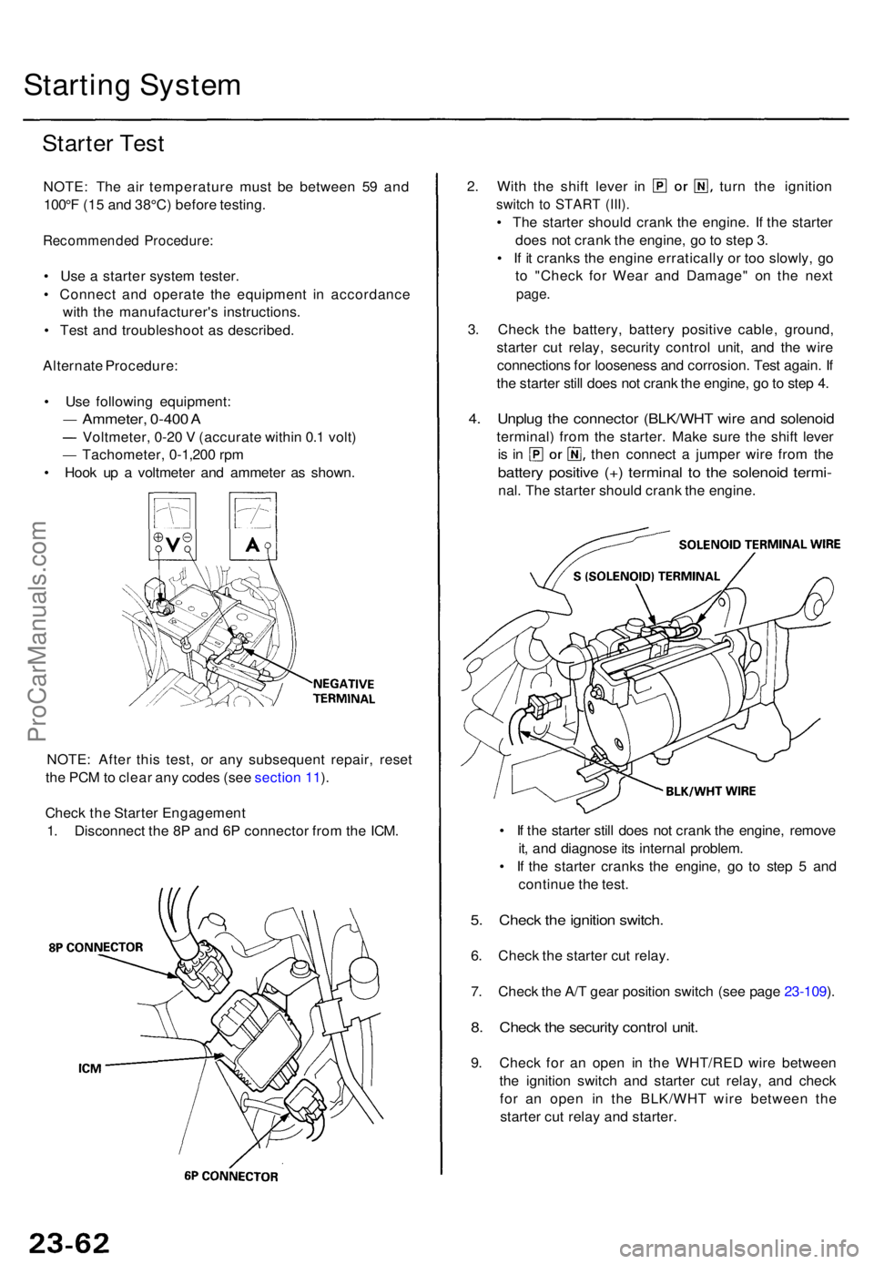
• Hoo k u p a voltmete r an d ammete r a s shown .
NOTE : Afte r thi s test , o r an y subsequen t repair , rese t
th e PC M to clea r an y code s (se e sectio n 11 ).
Chec k th e Starte r Engagemen t
1 . Disconnec t th e 8 P an d 6 P connecto r fro m th e ICM .
2. Wit h th e shif t leve r i n tur n th e ignitio n
switch t o STAR T (III) .
• Th e starte r shoul d cran k th e engine . I f th e starte r
doe s no t cran k th e engine , g o to ste p 3 .
• I f i t crank s th e engin e erraticall y o r to o slowly , g o
t o "Chec k fo r Wea r an d Damage " o n th e nex t
page .
3. Chec k th e battery , batter y positiv e cable , ground ,
starte r cu t relay , securit y contro l unit , an d th e wir e
connection s fo r loosenes s an d corrosion . Tes t again . I f
th e starte r stil l doe s no t cran k th e engine , g o to ste p 4 .
4. Unplu g th e connecto r (BLK/WH T wir e an d solenoi d
terminal ) fro m th e starter . Mak e sur e th e shif t leve r
is i n the n connec t a jumpe r wir e fro m th e
batter y positiv e (+ ) termina l t o th e solenoi d termi -
nal. Th e starte r shoul d cran k th e engine .
• I f th e starte r stil l doe s no t cran k th e engine , remov e
it , an d diagnos e it s interna l problem .
• I f th e starte r crank s th e engine , g o t o ste p 5 an d
continu e th e test .
5. Chec k th e ignitio n switch .
6. Chec k th e starte r cu t relay .
7 . Chec k th e A/ T gea r positio n switc h (se e pag e 23-109 ).
8 . Chec k th e securit y contro l unit .
9. Chec k fo r a n ope n i n th e WHT/RE D wir e betwee n
th e ignitio n switc h an d starte r cu t relay , an d chec k
fo r a n ope n i n th e BLK/WH T wir e betwee n th e
starte r cu t rela y an d starter .
ProCarManuals.com
Page 585 of 1771

Check for Wear and Damage
The starter should crank the engine smoothly and steadily.
If the starter engages, but cranks the engine erratically,
remove it, and inspect the starter drive gear and torque
converter ring gear for damage.
• Check the drive gear overrunning clutch for binding
or slipping when the armature is rotated with the
drive gear held. If the clutch is damaged, replace the
clutch assembly.
Check Cranking Voltage and Current Draw
Cranking voltage should be no less than 8.0 volts.
Current draw should be no more than 450 amperes.
If cranking voltage is too low, or current draw too high,
check for:
Dead or low battery
Open circuit in starter armature commutator segments
Starter armature dragging
Shorted armature winding
Excessive drag in engine
Check Cranking rpm
Engine speed during cranking should be above 100 rpm.
If speed is too low, check for:
Loose battery or starter terminals
Excessively worn starter brushes
Open circuit in commutator segments
Dirty or damaged helical spline or drive gear
Defective drive gear overrunning clutch
Check Starter Disengagement
With the shift lever in or , turn the ignition switch to
"START (III)", and release to "ON (II)". The starter drive
gear should disengage from the flywheel ring gear when
you release the key.
If the drive gear hangs upon the flywheel ring gear, check
for:
• Solenoid plunger and switch malfunction
• Dirty drive gear assembly or damaged overrunning
clutchProCarManuals.com
Page 595 of 1771

Ignition Syste m
Descriptio n
Ignition Timin g Contro l
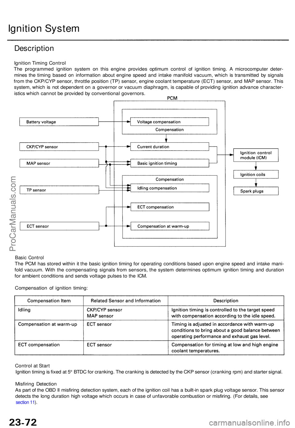
Th e programme d ignitio n syste m o n thi s engine provide s optimu m contro l o f ignitio n timing . A microcompute r deter -
mine s th e timin g base d o n informatio n abou t engin e spee d an d intak e manifol d vacuum , whic h i s transmitte d b y signal s
fro m th e CKP/CY P sensor , throttl e positio n (TP ) sensor , engin e coolan t temperatur e (ECT ) sensor , an d MA P sensor . Thi s
system , whic h i s no t dependen t o n a governo r o r vacuu m diaphragm , i s capabl e o f providin g ignitio n advanc e character -
istic s whic h canno t b e provide d b y conventiona l governors .
Basic Contro l
The PC M ha s store d withi n it th e basi c ignitio n timin g fo r operatin g condition s base d upo n engin e spee d an d intak e mani -
fol d vacuum . Wit h th e compensatin g signal s fro m sensors , th e syste m determine s optimu m ignitio n timin g an d duratio n
fo r ambien t condition s an d send s voltag e pulse s t o th e ICM .
Compensatio n o f ignitio n timing :
Contro l a t Star t
Ignitio n timin g is fixe d a t 5 ° BTD C fo r cranking . Th e crankin g is detecte d b y th e CK P senso r (crankin g rpm ) an d starte r signal .
Misfirin g Detectio n
A s par t o f th e OB D II misfirin g detectio n system , eac h o f th e ignitio n coi l ha s a built-i n spar k plu g voltag e sensor . Thi s senso r
detect s th e lon g duratio n hig h voltag e whic h occur s in cas e o f unfavorabl e combustio n o r misfiring . (Fo r details , se e
section 11 ).
ProCarManuals.com
Page 596 of 1771

Ignition Syste m
Ignition Timin g Inspectio n
SRS component s ar e locate d in thi s area . Revie w th e SR S
componen t locations , precautions , an d procedure s i n th e
SR S (sectio n 24 ) befor e performin g repair s o r service .
1 . Star t th e engine . Hol d th e engin e a t 3,00 0 rp m wit h
no loa d (shif t leve r i n position ) unti l th e
radiato r fa n come s on , the n le t i t idle .
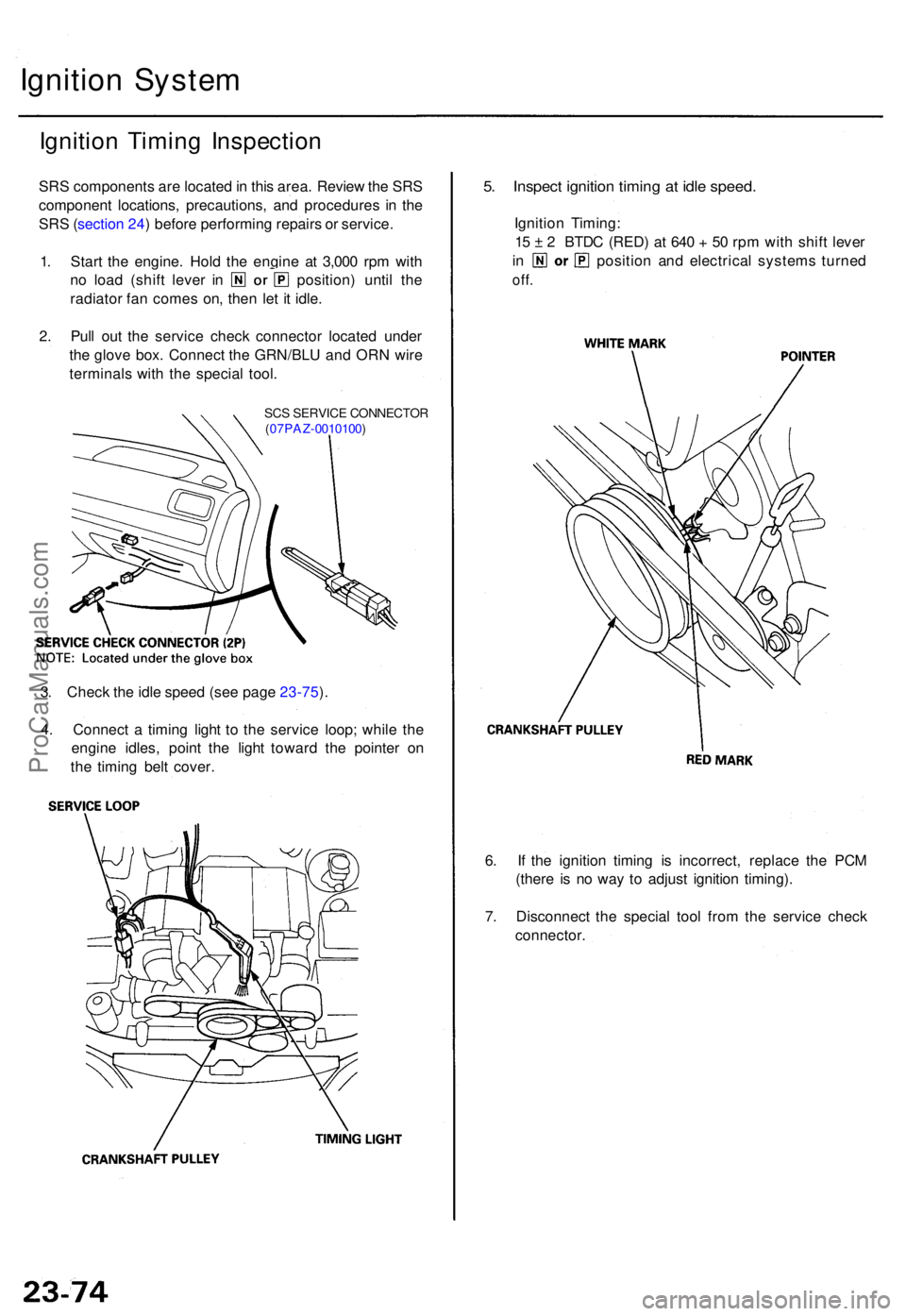
2 . Pul l ou t th e servic e chec k connecto r locate d unde r
th e glov e box . Connec t th e GRN/BL U an d OR N wir e
terminal s wit h th e specia l tool .
SCS SERVIC E CONNECTO R
( 07PAZ -0010100 )
5. Inspec t ignitio n timin g a t idl e speed .
Ignition Timing :
1 5 ± 2 BTD C (RED ) a t 64 0 + 50 rp m wit h shif t leve r
in positio n an d electrica l system s turne d
off.
6. I f th e ignitio n timin g i s incorrect , replac e th e PC M
(ther e i s n o wa y t o adjus t ignitio n timing) .
7 . Disconnec t th e specia l too l fro m th e servic e chec k
connector .
3
. Chec k th e idl e spee d (se e pag e 23-75 ).
4 . Connec t a timin g ligh t t o th e servic e loop ; whil e th e
engin e idles , poin t th e ligh t towar d th e pointe r o n
th e timin g bel t cover .
ProCarManuals.com
Page 597 of 1771
Idle Spee d Chec k
1. Star t th e engine . Hol d th e engin e a t 3,00 0 rp m wit h
no loa d unti l th e radiato r fa n
come s on , the n le t i t idle .
2 . Connec t a tachomete r t o th e tes t tachomete r connec -
tor.
Nois e Condense r Capacit y Tes t
1. Us e a commerciall y availabl e condense r tester .
Connec t th e condense r teste r probe s an d measur e
th e condense r capacity .
NOTE : Th e nois e condense r i s intende d t o reduc e
ignitio n noise . However , condense r failur e ma y caus e
th e engin e t o sto p running .
2 . I f no t withi n th e specifications , replac e th e nois e con -
denser .
3. Adjus t th e idl e spee d if necessar y (se e sectio n 11 ).
ProCarManuals.com
Page 609 of 1771
Fan Control s
Componen t Locatio n Inde x
ENGIN E COOLAN TTEMPERATUR E (ECT )SWITC H
Test , sectio n 10
Removal , sectio n 1 0
Radiato r Fa n Control :
Whe n th e engine oil temperatur e is abov e approximatel y 198° F (92°C ) afte r th e engin e ha s stopped , th e radiato r fa n wil l ru n
fo r abou t 1 5 minutes . Th e engin e coolan t temperatur e (ECT ) switc h i s i n th e thermosta t housing . Th e engin e oi l tempera -
tur e switc h i s locate d o n th e valv e cover . Th e radiato r fa n contro l modul e is locate d behin d th e glov e box .
ENGIN E OI L TEMPERATUR ESWITCHTest, sectio n 6
Replacement , sectio n 6
Test , page 23-109
Removal , sectio n 1 0 Test
, page 23-109
Removal , sectio n 1 0 Terminals
, page 23-93
Test
, page 23-62
Test, page 23-62
ProCarManuals.com