Page 795 of 1771

Piston Pin sPisto n Ring s
Installatio n
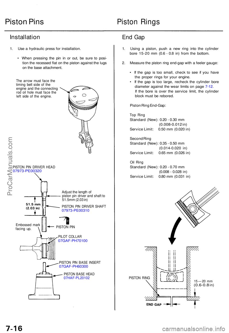
1. Us e a hydrauli c pres s fo r installation .
• Whe n pressin g th e pi n i n o r out , b e sur e t o posi -
tio n th e recesse d fla t o n th e pisto n agains t th e lug s
o n th e bas e attachment .
The arro w mus t fac e th etimin g bel t sid e o f th eengin e an d th e connectin grod oi l hole must fac e th eleft sid e o f th e engine .
End Ga p
PISTO N PI N DRIVE R HEA D07973-PE0032 0
Embossed mar kfacin g up .
Adjus t th e lengt h o fpisto n pi n drive r an d shaf t t o51.5m m (2.0 3 in )
PISTO N PI N DRIVE R SHAF T07973-PE0031 0
PISTON PI N
PILO T COLLA R07GAF-PH7010 0
1PISTON PI N BAS E INSER T07GAF-PH6030 0
PISTON BAS E HEA D07HAF-PL2010 2
1. Usin g a piston , pus h a ne w rin g int o th e cylinde r
bor e 15-2 0 m m (0. 6 - 0. 8 in ) fro m th e bottom .
2 . Measur e th e pisto n rin g end-ga p wit h a feele r gauge :
• I f th e ga p i s to o small , chec k t o se e i f yo u hav e
th e prope r ring s fo r you r engine .
• I f th e ga p i s to o large , rechec k th e cylinde r bor e
diamete r agains t th e wea r limit s o n pag e 7-12 .
I f th e bor e i s ove r th e servic e limit , th e cylinde r
bloc k mus t b e rebored .
Pisto n Rin g End-Gap :
Top Rin g
Standar d (New) : 0.2 0 - 0.3 0 m m
(0.008-0.01 2 in )
Servic e Limit : 0.5 0 m m (0.02 0 in )
Secon d Rin g
Standar d (New) : 0.3 5 - 0.5 0 m m
(0.014-0.02 0 in )
Servic e Limit : 0.6 5 m m (0.02 6 in )
Oil Rin g
Standar d (New) : 0.2 0 - 0.7 0 m m
(0.00 8 - 0.02 8 in )
Servic e Limit : 0.8 0 m m (0.03 1 in )
PISTO N RIN G15 — 2 0 m m(0.6-0. 8 in)
ProCarManuals.com
Page 798 of 1771

Pistons
Installation
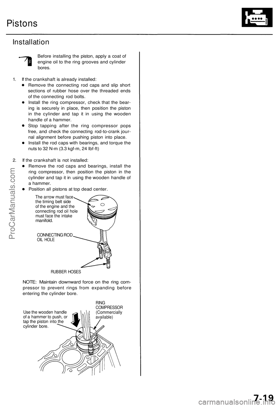
Before installing the piston, apply a coat of
engine oil to the ring grooves and cylinder
bores.
1. If the crankshaft is already installed:
Remove the connecting rod caps and slip short
sections of rubber hose over the threaded ends
of the connecting rod bolts.
Install the ring compressor, check that the bear-
ing is securely in place, then position the piston
in the cylinder and tap it in using the wooden
handle of a hammer.
Stop tapping after the ring compressor pops
free, and check the connecting rod-to-crank jour-
nal alignment before pushing piston into place.
Install the rod caps with bearings, and torque the
nuts to 32 N-m (3.3 kgf-m, 24 Ibf-ft)
2. If the crankshaft is not installed:
Remove the rod caps and bearings, install the
ring compressor, then position the piston in the
cylinder and tap it in using the wooden handle of
a hammer.
Position all pistons at top dead center.
The arrow must face
the timing belt side
of the engine and the
connecting rod oil hole
must face the intake
manifold.
CONNECTING ROD
OIL HOLE
RUBBER HOSES
NOTE: Maintain downward force on the ring com-
pressor to prevent rings from expanding before
entering the cylinder bore.
Use the wooden handle
of a hammer to push, or
tap the piston into the
cylinder bore.
RING
COMPRESSOR
(Commercially
available)ProCarManuals.com
Page 799 of 1771

Crankshaft
Installation
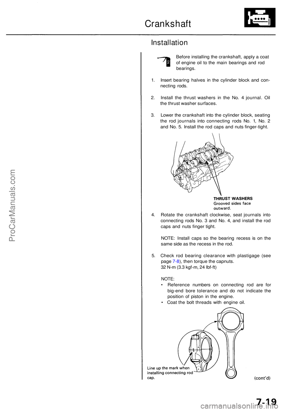
Before installin g th e crankshaft , appl y a coa t
o f engin e oi l t o th e mai n bearing s an d ro d
bearings .
1. Inser t bearin g halve s i n th e cylinde r bloc k an d con -
nectin g rods .
2 . Instal l th e thrus t washer s i n th e No . 4 journal . Oi l
th e thrus t washe r surfaces .
3 . Lowe r th e crankshaf t int o th e cylinde r block , seatin g
th e ro d journal s int o connectin g rod s No . 1 , No . 2
an d No . 5 . Instal l th e ro d cap s an d nut s finger-tight .
4 . Rotat e th e crankshaf t clockwise , sea t journal s int o
connectin g rod s No . 3 an d No . 4 , an d instal l th e ro d
cap s an d nut s finge r tight .
NOTE : Instal l cap s s o th e bearin g reces s i s o n th e
sam e sid e a s th e reces s in th e rod .
5 . Chec k ro d bearin g clearanc e wit h plastigag e (se e
pag e 7-8 ), the n torqu e th e capnuts .
3 2 N- m (3. 3 kgf-m , 2 4 Ibf-ft )
NOTE :
• Referenc e number s o n connectin g ro d ar e fo r
big-en d bor e toleranc e an d d o no t indicat e th e
positio n o f pisto n i n th e engine .
• Coa t th e bol t thread s wit h engin e oil .
ProCarManuals.com
Page 805 of 1771
Engine Oil
Inspection
1. Check engine oil level with the engine off and the car
parked on level ground.
2. Make certain that the oil level indicated on the dip-
stick is between the upper and lower marks.
3. If the level has dropped close to the lower mark, add
oil until it reaches the upper mark.
CAUTION: Insert the dipstick carefully to avoid
bending it.ProCarManuals.com
Page 806 of 1771
NOTE: Unde r norma l conditions , th e oi l filte r shoul d b e
replace d a t ever y othe r oi l change .
Unde r sever e conditions , th e oi l filte r shoul d b e replace d
a t eac h oi l change .
Replacemen t
Be carefu l whe n loosenin g th e drai n bol t
whil e th e engin e i s hot . Burn s ca n resul t becaus e th e oi l
temperatur e is ver y hot .
1 . War m u p th e engine .
2 . Drai n th e engin e oil .
3 . Reinstal l th e drai n bol t wit h a ne w washer , an d refil l
with th e recommende d oil .
Engin e Oi l
ProCarManuals.com
Page 807 of 1771
The numbers in the middle of the API Service label tell
you the oil's SAE viscosity or weight. Select the oil for
your car according to this chart:
An oil with a viscosity of 5W - 30 is preferred for
improved fuel economy and year-round protection in the
car. You may use a 10W - 30 oil if the climate in your area
is limited to the temperature range shown on the chart.
4. Fill the engine with oil up to the specified level, run
the engine for more than three minutes, then check
for oil leakage.ProCarManuals.com
Page 808 of 1771
Oil Filter
Replacement
Be careful when loosening the oil filter
while the engine is hot. Burns can result because the oil
temperature is very high.
1. Remove the oil filter with the special oil filter wrench.
2. Inspect the threads and rubber seal on the new fil-
ter. Wipe off the seat on the engine block, then
apply a light coat of oil to the filter rubber seal.
NOTE: Use only filters with a built-in bypass system.ProCarManuals.com
Page 810 of 1771

Oil Pressur e
Testing
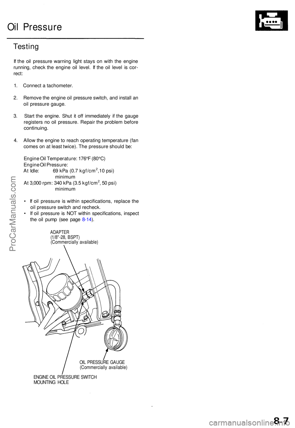
If th e oi l pressur e warnin g ligh t stay s o n wit h th e engin e
running , chec k th e engine oil level . I f th e oi l leve l i s cor -
rect :
1 . Connec t a tachometer .
2 . Remov e th e engin e oi l pressur e switch , an d instal l a n
oi l pressur e gauge .
3 . Star t th e engine . Shu t i t of f immediatel y i f th e gaug e
register s n o oi l pressure . Repai r th e proble m befor e
continuing .
4. Allo w th e engin e to reac h operatin g temperatur e (fa n
come s o n a t leas t twice) . Th e pressur e shoul d be :
Engin e Oi l Temperature : 176° F (80°C )
Engin e Oi l Pressure :
A t Idle : 6 9 kP a (0. 7 kgf/cm
2,1 0 psi )
minimu m
A t 3,00 0 rpm : 34 0 kP a (3. 5 kgf/cm
2, 5 0 psi )
minimu m
• I f oi l pressur e i s withi n specifications , replac e th e
oi l pressur e switc h an d recheck .
• I f oi l pressur e is NO T withi n specifications , inspec t
th e oi l pum p (se e pag e 8-14 ).
ADAPTE R(1/8"-28, BSPT )(Commerciall y available )
OIL PRESSUR E GAUG E(Commerciall y available )
ENGINE OI L PRESSUR E SWITC HMOUNTIN G HOL E
ProCarManuals.com