1995 ACURA TL gearbox
[x] Cancel search: gearboxPage 28 of 1771

Lubrication Points
For the details of lubrication points and types of lubricants to be applied, refer to the illustrated index and various work
procedures (such as Assembly/Reassembly, Replacement, Overhaul, Installation, etc.) contained in each section.
No.
1
2
3
4
5
6
7
8
9
10
11
12
13
14
15
16
17
18
19
20
21
LUBRICATION POINTS
Engine
Transmission
Brake Line (Includes Anti-lock brake line)
Power steering gearbox
Steering boots
Throttle cable end
Steering ball joints
Shift lever (Automatic transmission)
Pedal linkage
Intermediate shaft
Brake master cylinder pushrod
Fuel
fill
lid
Trunk hinges
Door hinges upper and lower
Door opening detents
Hood hinges and hood latch
Brake pipe joint (Front and rear wheel house)
Caliper Piston seal, Dust seal,
Caliper pin, Piston
Power steering system
Differential
A/C compressor
LUBRICANT
API Service Grade: Use SH "Energy Conserving II" or SJ
"Energy Conserving" grade oil.
The oil container may also display the API Certification
mark shown below. Make sure it says "For Gasoline
Engines."
SAE Viscosity: See chart below.
Genuine Honda Premium Formula Automatic
Transmission Fluid (ATF)*1
Genuine Honda DOT3 Brake Fluid*2
Steering grease P/N 08733 - B070E
Multi-purpose grease
Honda White Lithium Grease
Rust preventives
Silicone grease
Genuine Honda Power Steering Fluid-V or S*3
Hypoid gear Oil API service GL4 or GL5
Viscosity:
at above -18°C (0°F): SAE 90
at less than -18°C (0°F): SAE 80 W-90
Compressor oil:
DENSO: ND-OIL8 (P/N 38897 - PR7 - A01 AH or 38899 -
PR7-A01)
(For Refrigerant: HFC-134a (R-134a))
API SERVICE LABEL
API CERTIFICATION MARK
Recommended Engine Oil
Engine oil viscosity for ambient temperature ranges
NOTE: The following information as marked *1, *2 and *3 on above chart details for 1997 model:
*1: Always use Genuine Honda Premium Formula Automatic Transmission Fluid (ATF). Using a non-Honda ATF can affect
shift quality.
*2: Always use Genuine Honda DOT3 Brake Fluid. Using a non-Honda brake fluid can cause corrosion and decrease the
life of the system.
*3: Always use Genuine Honda Power Steering Fluid-V or S. Using any other type of power steering fluid or automatic
transmission fluid can cause increase wear and poor steering in cold weather.ProCarManuals.com
Page 469 of 1771
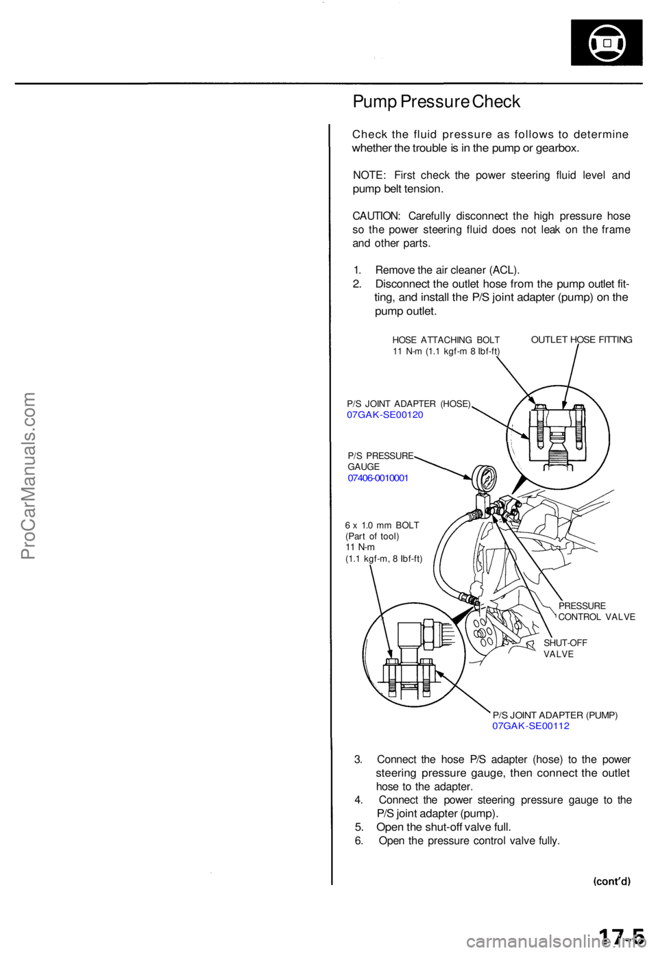
Pump Pressur e Chec k
Chec k th e flui d pressur e a s follow s t o determin e
whether th e troubl e is in th e pum p o r gearbox .
NOTE: Firs t chec k th e powe r steerin g flui d leve l an d
pum p bel t tension .
CAUTION : Carefull y disconnec t th e hig h pressur e hos e
s o th e powe r steerin g flui d doe s no t lea k o n th e fram e
an d othe r parts .
1 . Remov e th e ai r cleane r (ACL) .
2. Disconnec t th e outle t hos e fro m th e pum p outle t fit -
ting , an d instal l th e P/ S join t adapte r (pump ) o n th e
pum p outlet .
HOSE ATTACHIN G BOL T
1 1 N- m (1. 1 kgf- m 8 Ibf-ft )
P/ S JOIN T ADAPTE R (HOSE )
07GAK-SE0012 0
P/S PRESSUR E
GAUG E
07406-001000 1
OUTLET HOS E FITTIN G
6 x 1. 0 m m BOL T
(Par t o f tool )
11 N- m(1.1 kgf-m , 8 Ibf-ft )
PRESSURE
CONTRO L VALV E
SHUT-OF F
VALV E
P/S JOIN T ADAPTE R (PUMP )07GAK-SE0011 2
3. Connec t th e hos e P/ S adapte r (hose ) t o th e powe r
steerin g pressur e gauge , the n connec t th e outle t
hose t o th e adapter .
4 . Connec t th e powe r steerin g pressur e gaug e t o th e
P/S join t adapte r (pump) .
5. Ope n th e shut-of f valv e full .
6. Ope n th e pressur e contro l valv e fully .
ProCarManuals.com
Page 473 of 1771
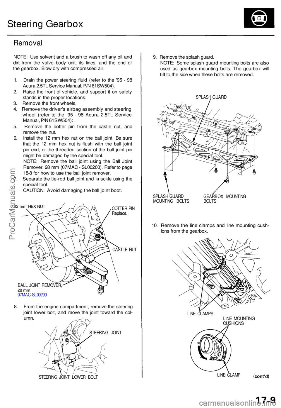
Steering Gearbo x
Remova l
NOTE: Us e solven t an d a brus h t o was h of f an y oi l an d
dir t fro m th e valv e bod y unit , it s lines , an d th e en d o f
th e gearbox . Blo w dr y wit h compresse d air .
1 . Drai n th e powe r steerin g flui d (refe r t o th e '9 5 - 9 8
Acur a 2.5T L Servic e Manual , P/ N 61SW504) .
2 . Rais e th e fron t o f vehicle , an d suppor t i t o n safet y
stand s in th e prope r locations .
3 . Remov e th e fron t wheels .
4 . Remov e th e driver' s airba g assembl y an d steerin g
whee l (refe r t o th e '9 5 - 9 8 Acur a 2.5T L Servic e
Manual , P/ N 61SW504) :
5 . Remov e th e cotte r pi n fro m th e castl e nut , an d
remov e th e nut .
6 . Instal l th e 1 2 m m he x nu t o n th e bal l joint . B e sur e
tha t th e 1 2 m m he x nu t i s flus h wit h th e bal l join t
pi n end , o r th e threade d sectio n o f th e bal l join t pi n
migh t b e damage d b y th e specia l tool .
NOTE : Remov e th e bal l join t usin g th e Bal l Join t
Remover , 2 8 m m (07MA C - SL00200) . Refe r t o pag e
18- 8 fo r ho w to us e th e bal l join t remover .
7 . Separat e th e tie-ro d bal l join t an d knuckl e usin g th e
specia l tool .
CAUTION : Avoi d damagin g th e bal l join t boot .
12 m m HE X NU TCOTTE R PI NReplace .
CASTLE NU T
BAL L JOIN T REMOVER ,
28 m m07MA C-SL0020 0
8. Fro m th e engin e compartment , remov e th e steerin g
join t lowe r bolt , an d mov e th e join t towar d th e col -
umn .
STEERIN G JOIN T LOWE R BOL T
9. Remov e th e splas h guard .
NOTE : Som e splas h guar d mountin g bolt s ar e als o
use d a s gearbo x mountin g bolts . Th e gearbo x wil l
tilt to th e sid e whe n thes e bolts are removed .
SPLASH GUAR D
SPLAS H GUAR D
MOUNTIN G BOLT S GEARBO
X MOUNTIN G
BOLTS
10. Remov e th e lin e clamp s an d lin e mountin g cush -
ions fro m th e gearbox .
LINE CLAMP SLINE MOUNTIN GCUSHIONS
LINE CLAM P
STEERIN
G JOIN T
ProCarManuals.com
Page 474 of 1771
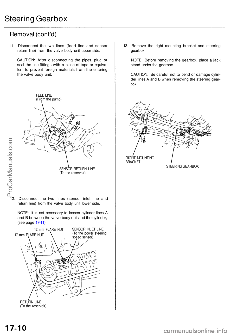
Steering Gearbo x
Remova l (cont'd )
11. Disconnec t th e tw o line s (fee d lin e an d senso r
retur n line ) fro m th e valv e bod y uni t uppe r side .
CAUTION : Afte r disconnectin g th e pipes , plu g o r
sea l th e lin e fitting s wit h a piec e o f tap e o r equiva -
len t t o preven t foreig n material s fro m th e enterin g
th e valv e bod y unit :
FEED LIN E(Fro m th e pump )
SENSO R RETUR N LIN E
(T o th e reservoir )
12. Disconnec t th e tw o line s (senso r inle t lin e an d
retur n line ) fro m th e valv e bod y uni t lowe r side .
NOTE : I t i s no t necessar y t o loose n cylinde r line s A
an d B betwee n th e valv e bod y uni t an d th e cylinder ,
(see pag e 17-11 )
12 m m FLAR E NU T
17 m m FLAR E NU T SENSO
R INLE T LIN E
(T o th e powe r steerin g
spee d sensor )
RETUR N LIN E
(T o th e reservoir )
13. Remov e th e righ t mountin g bracke t an d steerin g
gearbox .
NOTE : Befor e removin g th e gearbox , plac e a jac k
stan d unde r th e gearbox.
CAUTION : B e carefu l no t t o ben d o r damag e cylin -
de r line s A an d B whe n removin g th e steerin g gear -
box.
RIGH T MOUNTIN GBRACKET
STEERIN G GEARBO X
ProCarManuals.com
Page 475 of 1771
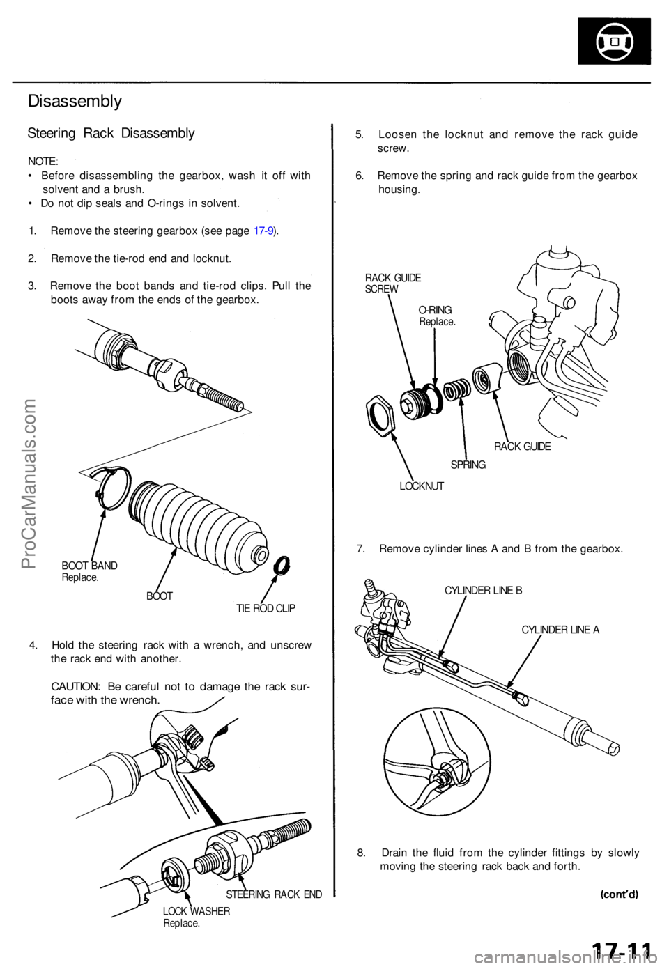
Disassembly
Steering Rac k Disassembl y
NOTE:
• Befor e disassemblin g th e gearbox , was h i t of f wit h
solven t an d a brush .
• D o no t di p seal s an d O-ring s i n solvent .
1 . Remov e th e steerin g gearbo x (se e pag e 17-9 ).
2 . Remov e th e tie-ro d en d an d locknut .
3 . Remov e th e boo t band s an d tie-ro d clips . Pul l th e
boot s awa y fro m th e end s o f th e gearbox .
BOOT BAN DReplace .
BOOTTIE RO D CLI P
4. Hol d th e steerin g rac k wit h a wrench , an d unscre w
th e rac k en d wit h another .
CAUTION : B e carefu l no t t o damag e th e rac k sur -
face wit h th e wrench .
STEERIN G RAC K EN D
LOC K WASHE RReplace.
5. Loose n th e locknu t an d remov e th e rac k guid e
screw .
6 . Remov e th e sprin g an d rac k guid e fro m th e gearbo x
housing .
RACK GUID ESCRE W
RACK GUID E
SPRIN G
LOCKNU T
7. Remov e cylinde r line s A an d B fro m th e gearbox .
CYLINDER LIN E B
CYLINDE R LIN E A
8. Drai n th e flui d fro m th e cylinde r fitting s b y slowl y
movin g th e steerin g rac k bac k an d forth .
O-RIN GReplace .
ProCarManuals.com
Page 476 of 1771
Steering Gearbo x
Disassembl y (cont'd )
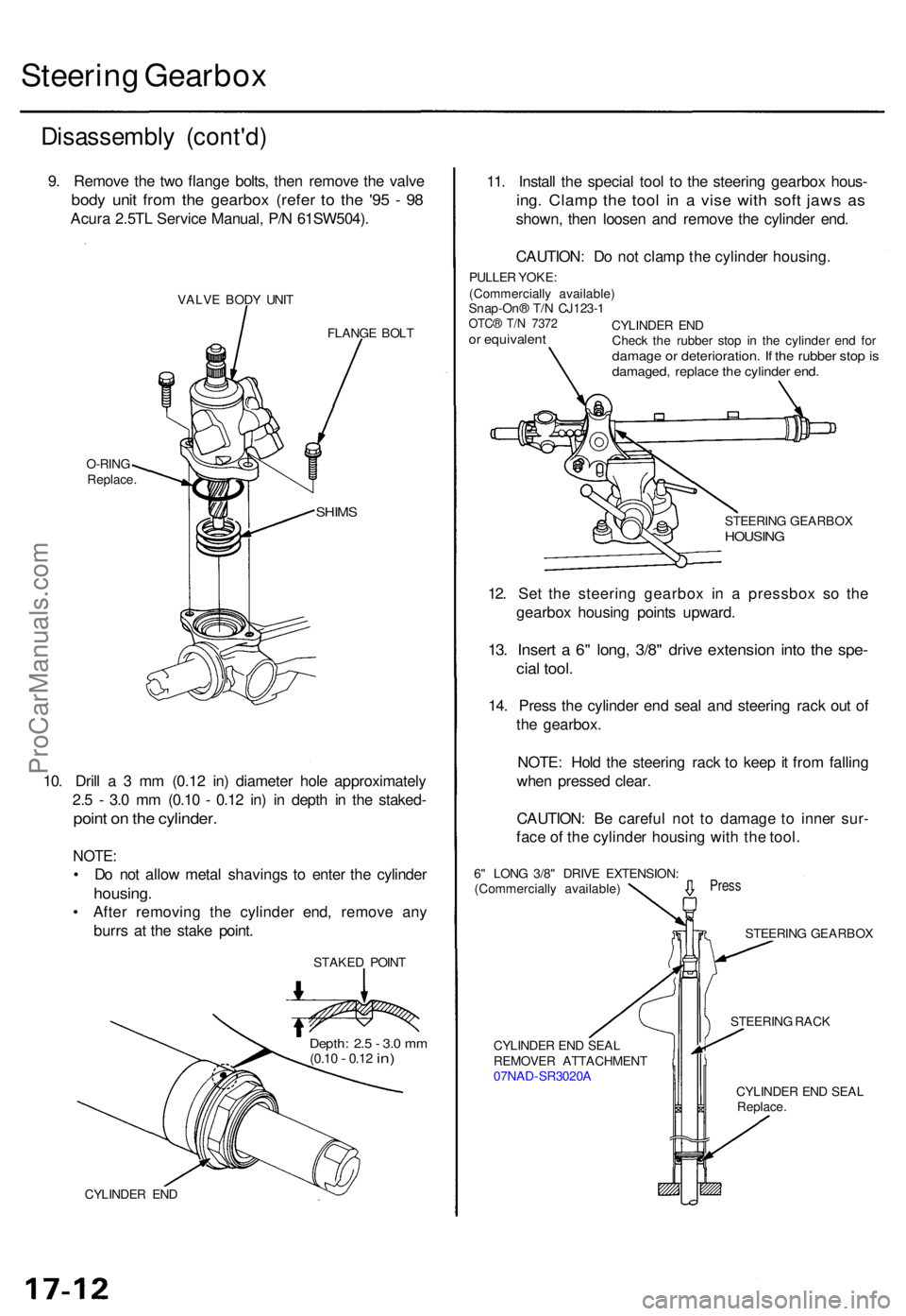
9. Remov e th e tw o flang e bolts , the n remov e th e valv e
body uni t fro m th e gearbo x (refe r t o th e '9 5 - 9 8
Acur a 2.5T L Servic e Manual , P/ N 61SW504) .
VALVE BOD Y UNI T
FLANGE BOL T
10. Dril l a 3 m m (0.1 2 in ) diamete r hol e approximatel y
2. 5 - 3. 0 m m (0.1 0 - 0.1 2 in ) i n dept h i n th e staked -
point o n th e cylinder .
NOTE:
• D o no t allo w meta l shaving s t o ente r th e cylinde r
housing .
• Afte r removin g th e cylinde r end , remov e an y
burr s a t th e stak e point .
STAKE D POIN T
CYLINDE R EN D
11. Instal l th e specia l too l t o th e steerin g gearbo x hous -
ing. Clam p th e too l i n a vis e wit h sof t jaw s a s
shown , the n loose n an d remov e th e cylinde r end .
CAUTION : D o no t clam p th e cylinde r housing .
PULLER YOKE :
(Commerciall y available )
Snap-On ® T/ N CJ123- 1
OTC® T/ N 737 2or equivalen t
STEERING GEARBO XHOUSING
STEERIN G RAC K
CYLINDE R EN D SEA L
REMOVE R ATTACHMEN T
07NA D-SR3020 A
CYLINDER EN D SEA L
Replace .
SHIMS
O-RIN G
Replace . CYLINDE
R EN D
Chec k th e rubbe r sto p i n th e cylinde r en d fo r
damag e o r deterioration . I f th e rubbe r sto p isdamaged , replac e th e cylinde r end .
Depth : 2. 5 - 3. 0 m m(0.1 0 - 0.12 in)
12. Se t th e steerin g gearbo x i n a pressbo x s o th e
gearbo x housin g point s upward .
13. Inser t a 6" long , 3/8 " driv e extensio n int o th e spe -
cial tool .
14. Pres s th e cylinde r en d sea l an d steerin g rac k ou t o f
th e gearbox .
NOTE : Hol d th e steerin g rac k t o kee p it fro m fallin g
whe n presse d clear .
CAUTION : B e carefu l no t t o damag e t o inne r sur -
fac e o f th e cylinde r housin g wit h th e tool .
Pres s
STEERIN G GEARBO X
6
" LON G 3/8 " DRIV E EXTENSION :
(Commerciall y available )
ProCarManuals.com
Page 477 of 1771
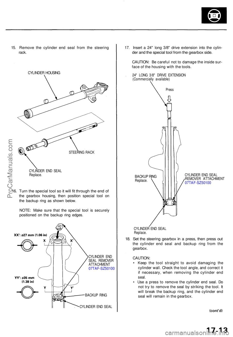
15. Remov e th e cylinde r en d sea l fro m th e steerin g
rack .
CYLINDE R HOUSIN G
STEERIN G RAC K
CYLINDE R EN D SEA L
Replace .
16. Tur n th e specia l too l s o it wil l fi t throug h th e en d o f
the gearbo x housing , the n positio n specia l too l o n
th e backu p rin g a s show n below .
NOTE : Mak e sur e tha t th e specia l too l i s securel y
positione d o n th e backu p rin g edges .
CYLINDE R EN D
SEA L REMOVE R
ATTACHMEN T
07TAF-SZ5010 0
BACKUP RIN G
CYLINDE R EN D SEA L
17. Inser t a 24 " lon g 3/8 " driv e extensio n int o th e cylin -
der an d th e specia l too l fro m th e gearbo x side .
CAUTION : B e carefu l no t t o damag e th e insid e sur -
fac e o f th e housin g wit h th e tools .
24" LON G 3/8 " DRIV E EXTENSIO N
(Commerciall y available )
Press
BACKU P RIN GReplace . CYLINDE
R EN D SEA L
REMOVE R ATTACHMEN T07TAF-SZ5010 0
CYLINDER EN D SEA LReplace .
18. Se t th e steerin g gearbo x in a press , the n pres s ou t
the cylinde r en d sea l an d backu p rin g fro m th e
gearbox .
CAUTION :
• Kee p th e too l straigh t t o avoi d damagin g th e
cylinde r wall . Chec k th e too l angle , an d correc t i t
i f necessary , whe n removin g th e cylinde r en d
seal .
• Us e a pres s t o remov e th e cylinde r en d seal . D o
no t tr y t o remov e th e sea l b y strikin g th e tool . I t
wil l brea k th e backu p ring , an d th e cylinde r en d
sea l wil l remai n in th e gearbox .
ProCarManuals.com
Page 478 of 1771
Steering Gearbo x
Disassembl y (cont'd )
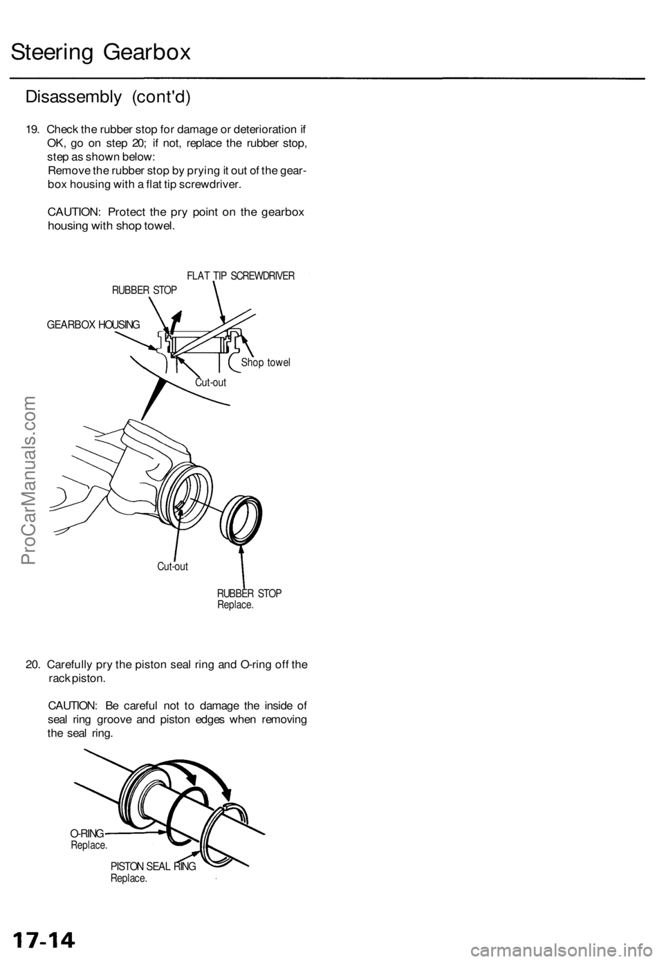
19. Chec k th e rubbe r sto p fo r damag e o r deterioratio n if
OK , g o o n ste p 20 ; i f not , replac e th e rubbe r stop ,
ste p a s show n below :
Remov e th e rubbe r sto p b y pryin g it ou t o f th e gear -
bo x housin g wit h a fla t ti p screwdriver .
CAUTION: Protec t th e pr y poin t o n th e gearbo x
housing wit h sho p towel .
FLAT TI P SCREWDRIVE R
GEARBOX HOUSIN G
Shop towe l
RUBBE R STO P
Replace .
20. Carefull y pr y th e pisto n sea l rin g an d O-rin g of f th e
rac k piston .
CAUTION : B e carefu l no t t o damag e th e insid e o f
sea l rin g groov e an d pisto n edge s whe n removin g
th e sea l ring .
O-RIN GReplace .
PISTON SEA L RIN GReplace .
RUBBE
R STO P
Cut-ou t
Cut-ou t
ProCarManuals.com