1995 ACURA TL gearbox
[x] Cancel search: gearboxPage 1156 of 1771
Troubleshooting
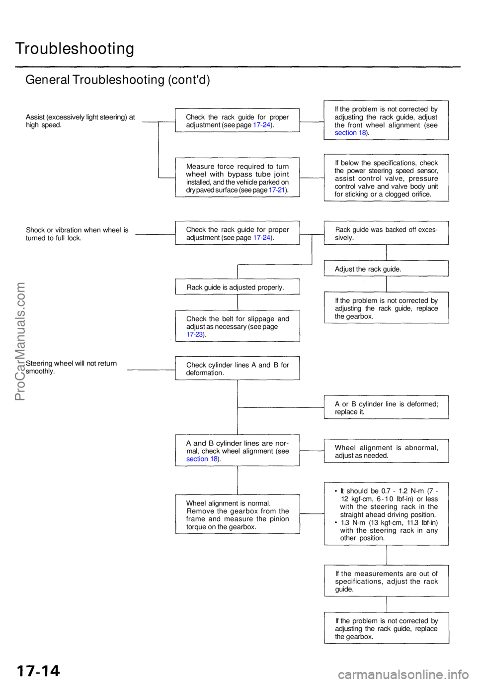
General Troubleshootin g (cont'd )
Assist (excessivel y ligh t steering ) a thig h speed . Chec
k th e rac k guid e fo r prope r
adjustmen t (se e pag e 17-24 ).
Measur e forc e require d t o tur n
whee l wit h bypas s tub e join tinstalled , an d th e vehicl e parke d o n
dr y pave d surfac e (se e pag e 17-21 ). I
f th e proble m is no t correcte d b y
adjustin g th e rac k guide , adjus tthe fron t whee l alignmen t (se e
sectio n 18 ).
I f belo w th e specifications , chec k
th e powe r steerin g spee d sensor ,
assis t contro l valve , pressur e
contro l valv e an d valv e bod y uni t
fo r stickin g o r a clogge d orifice .
Shoc k o r vibratio n whe n whee l i s
turne d t o ful l lock . Chec
k th e rac k guid e fo r prope r
adjustmen t (se e pag e 17-24 ).
Rac k guid e is adjuste d properly .
Chec k th e bel t fo r slippag e an d
adjus t a s necessar y (se e pag e
17-23 ).
Rac k guid e wa s backe d of f exces -sively.
Adjus t th e rac k guide .
I f th e proble m is no t correcte d b y
adjustin g th e rac k guide , replac e
th e gearbox .
Steering whee l wil l no t retur nsmoothly . Chec
k cylinde r line s A an d B fo r
deformation .
A an d B cylinde r line s ar e nor -mal, chec k whee l alignmen t (se e
sectio n 18 ).
Whee l alignmen t i s normal .
Remov e th e gearbo x fro m th e
fram e an d measur e th e pinio n
torqu e o n th e gearbox . A
o r B cylinde r lin e i s deformed ;
replac e it .
Whee l alignmen t i s abnormal ,
adjus t a s needed .
I t shoul d b e 0. 7 - 1. 2 N- m (7 -
1 2 kgf-cm , 6-1 0 Ibf-in ) o r les s
wit h th e steerin g rac k i n th e
straigh t ahea d drivin g position .
1. 3 N- m (1 3 kgf-cm , 11. 3 Ibf-in )
wit h th e steerin g rac k i n an y
othe r position .
I f th e measurement s ar e ou t o f
specifications , adjus t th e rac k
guide .
I f th e proble m is no t correcte d b y
adjustin g th e rac k guide , replac ethe gearbox .
ProCarManuals.com
Page 1157 of 1771
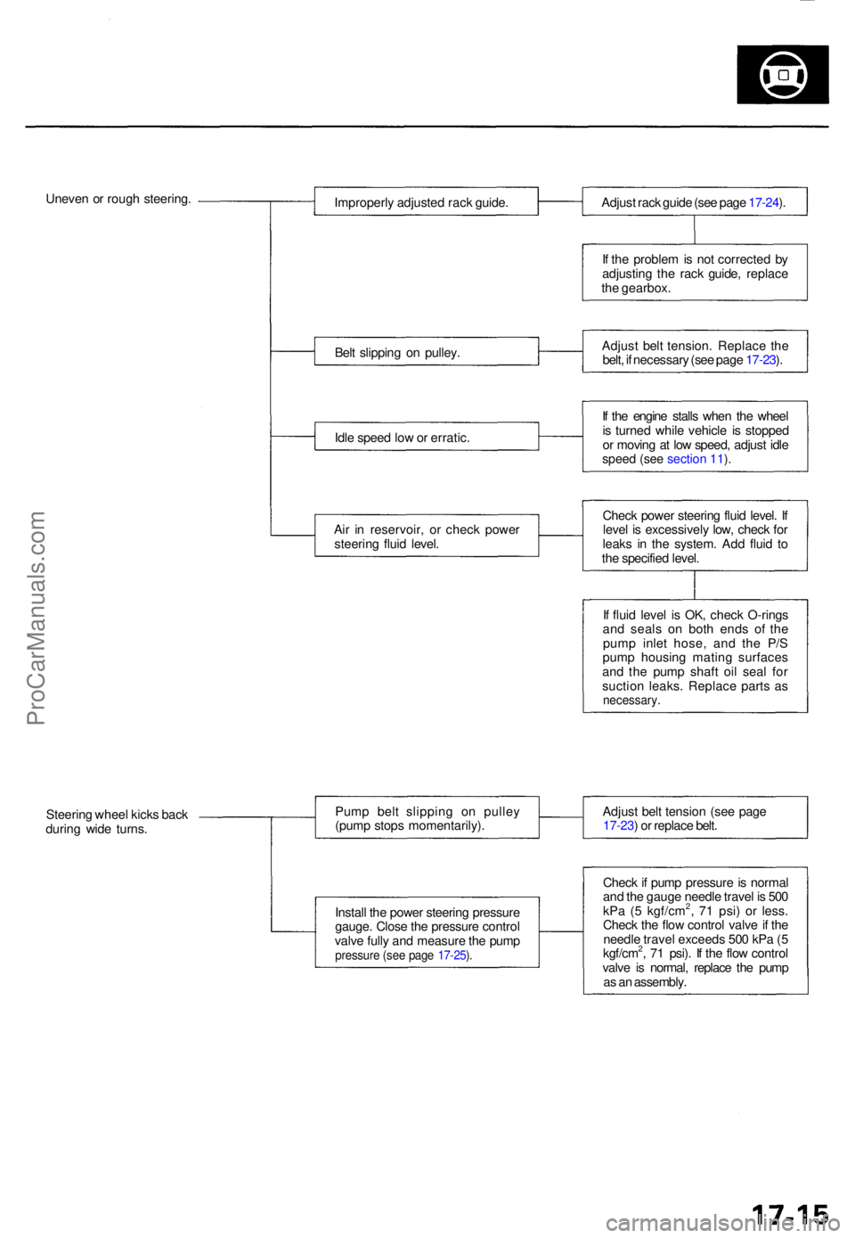
Uneven o r roug h steering .
Improperly adjuste d rac k guide .
Bel t slippin g o n pulley .
Idl e spee d lo w o r erratic .
Ai r i n reservoir , o r chec k powe r
steerin g flui d level . Adjus
t rac k guid e (se e pag e 17-24 ).
I f th e proble m is no t correcte d b y
adjustin g th e rac k guide , replac e
th e gearbox .
Adjus t bel t tension . Replac e th e
belt , i f necessar y (se e pag e 17-23 ).
I f th e engin e stall s whe n th e whee l
i s turne d whil e vehicl e i s stoppe d
o r movin g a t lo w speed , adjus t idl e
speed (see section 11).
Check powe r steerin g flui d level . I f
leve l i s excessivel y low , chec k fo r
leak s i n th e system . Ad d flui d t o
th e specifie d level .
I f flui d leve l i s OK , chec k O-ring s
an d seal s o n bot h end s o f th e
pum p inle t hose , an d th e P/ S
pum p housin g matin g surface s
an d th e pum p shaf t oi l sea l fo r
suctio n leaks . Replac e part s a s
necessary .
Steering whee l kick s bac k
durin g wid e turns . Pum
p bel t slippin g o n pulle y
(pum p stop s momentarily) .
Instal l th e powe r steerin g pressur e
gauge . Clos e th e pressur e contro l
valv e full y an d measur e th e pum p
pressur e (se e pag e 17-25 ).
Adjus t bel t tensio n (se e pag e
17-23 ) o r replac e belt .
Chec k if pum p pressur e is norma l
an d th e gaug e needl e trave l i s 50 0
kP a ( 5 kgf/cm
2, 7 1 psi ) o r less .
Chec k th e flo w contro l valv e if th e
needl e trave l exceed s 50 0 kP a ( 5
kgf/cm
2, 7 1 psi) . I f th e flo w contro l
valv e i s normal , replac e th e pum p
a s a n assembly .
ProCarManuals.com
Page 1167 of 1771
Pump Pressur e Chec k
Chec k th e flui d pressur e a s follow s t o determin e
whethe r th e troubl e i s i n th e pum p o r gearbox .
NOTE : Firs t chec k th e powe r steerin g flui d leve l an d
pum p bel t tension .
CAUTION : Disconnec t th e hig h pressur e hos e wit h car e
s o a s no t t o spil l th e powe r steerin g flui d o n th e fram e
an d othe r parts .
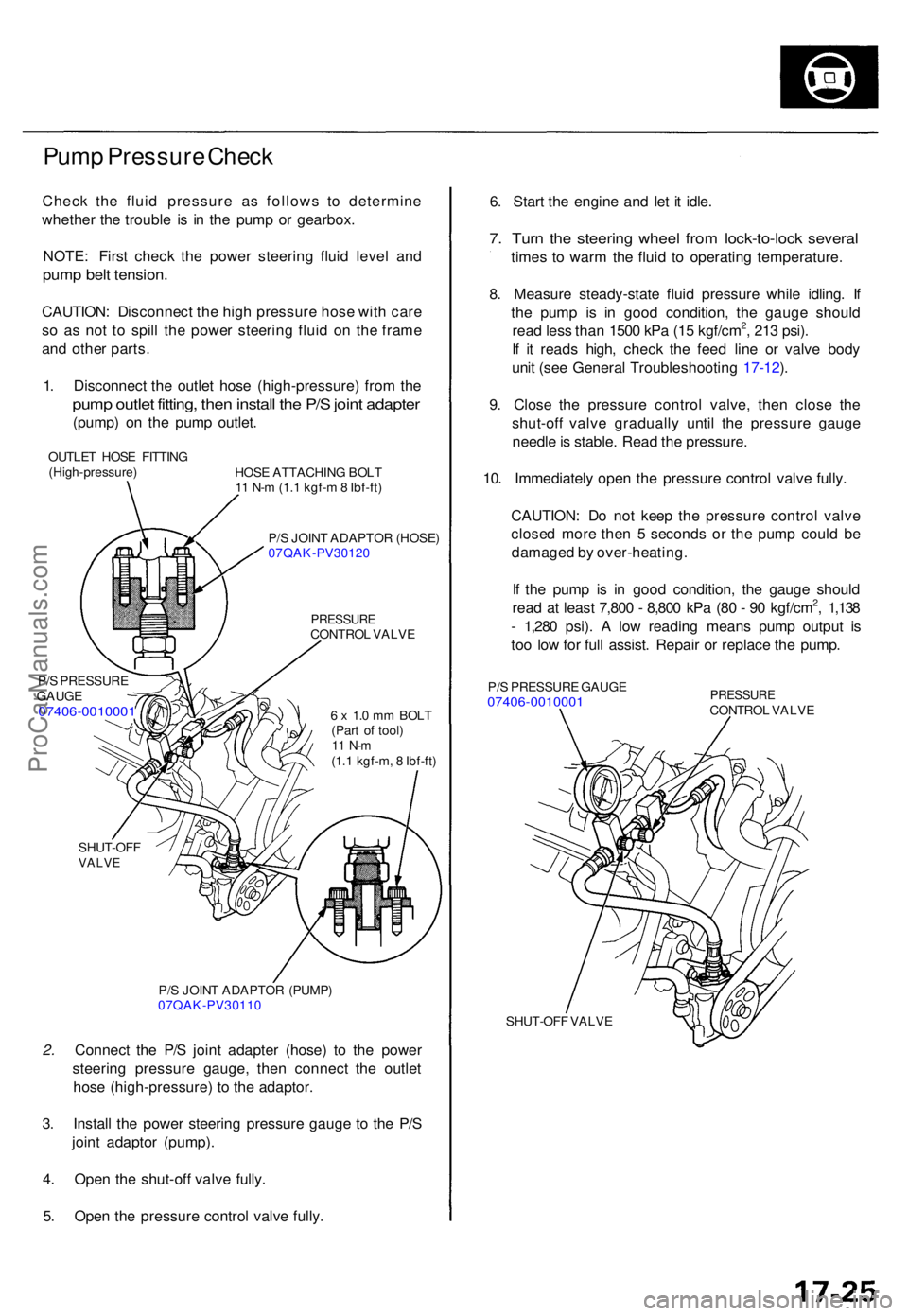
1 . Disconnec t th e outle t hos e (high-pressure ) fro m th e
pum p outle t fitting , the n instal l th e P/ S join t adapte r
(pump) o n th e pum p outlet .
OUTLE T HOS E FITTIN G
(High-pressure )
P/ S PRESSUR E
GAUG E
07406-001000 1
HOSE ATTACHIN G BOL T
1 1 N- m (1. 1 kgf- m 8 Ibf-ft )
P/ S JOIN T ADAPTO R (HOSE )
07QAK-PV3012 0
PRESSURECONTROL VALV E
6 x 1. 0 m m BOL T
(Par t o f tool )
11 N- m(1.1 kgf-m , 8 Ibf-ft )
SHUT-OF F
VALVE
P/S JOIN T ADAPTO R (PUMP )
07QAK-PV3011 0
2. Connec t th e P/ S join t adapte r (hose ) t o th e powe r
steerin g pressur e gauge , the n connec t th e outle t
hos e (high-pressure ) t o th e adaptor .
3 . Instal l th e powe r steerin g pressur e gaug e t o th e P/ S
join t adapto r (pump) .
4 . Ope n th e shut-of f valv e fully .
5 . Ope n th e pressur e contro l valv e fully . 6
. Star t th e engine and le t i t idle .
7. Tur n th e steerin g whee l fro m lock-to-loc k severa l
times t o war m th e flui d t o operating temperature .
8 . Measur e steady-stat e flui d pressur e whil e idling . I f
th e pum p i s i n goo d condition , th e gaug e shoul d
rea d les s tha n 150 0 kP a (1 5 kgf/cm
2, 21 3 psi) .
I f i t read s high , chec k th e fee d lin e o r valv e bod y
uni t (se e Genera l Troubleshootin g 17-12 ).
9 . Clos e th e pressur e contro l valve , the n clos e th e
shut-of f valv e graduall y unti l th e pressur e gaug e
needl e is stable . Rea d th e pressure .
10 . Immediatel y ope n th e pressur e contro l valv e fully .
CAUTION : D o no t kee p th e pressur e contro l valv e
close d mor e the n 5 second s o r th e pum p coul d b e
damage d b y over-heating .
I f th e pum p i s i n goo d condition , th e gaug e shoul d
rea d a t leas t 7,80 0 - 8,80 0 kP a (8 0 - 9 0 kgf/cm
2, 1,13 8
- 1,28 0 psi) . A lo w readin g mean s pum p outpu t i s
to o lo w fo r ful l assist . Repai r o r replac e th e pump .
P/S PRESSUR E GAUG E07406-001000 1 PRESSUR ECONTROL VALV E
SHUT-OF F VALV E
ProCarManuals.com
Page 1191 of 1771
Steering Gearbo x
Remova l
NOTE: Us e solven t an d a brus h t o was h of f an y oi l an d
dirt fro m th e valv e bod y unit , it s lines , an d th e en d o f
the gearbox . Blo w dr y wit h compresse d air .
1. Drai n th e powe r steerin g flui d a s describe d o n pag e
17-24 .
2. Rais e th e fron t o f vehicle , an d suppor t i t o n safet y
stands in th e prope r locations , (se e sectio n 1 )
3 . Remov e th e fron t wheels .
4 . Remov e th e driver' s airba g assembl y an d steerin g
whee l (se e pag e 17-27 ).
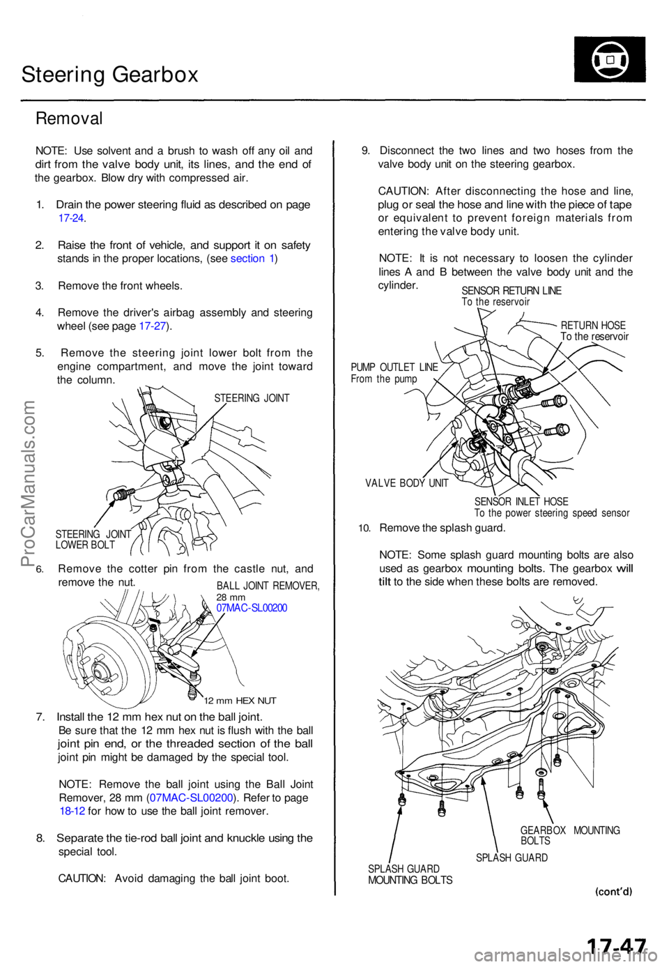
5 . Remov e th e steerin g join t lowe r bol t fro m th e
engin e compartment , an d mov e th e join t towar d
th e column .
STEERIN G JOIN T
6.
STEERIN G JOIN T
LOWE R BOL T
Remov e th e cotte r pi n fro m th e castl e nut , an d
remov e th e nut .
12 m m HE X NU T
7. Instal l th e 1 2 m m he x nu t o n th e bal l joint .
Be sur e tha t th e 1 2 m m he x nu t i s flus h wit h th e bal l
joint pi n end , o r th e threade d sectio n o f th e bal l
joint pi n migh t b e damage d b y th e specia l tool .
NOTE : Remov e th e bal l join t usin g th e Bal l Join t
Remover , 2 8 m m (07MA C-SL00200 ). Refe r t o pag e
18-12 for ho w to us e th e bal l join t remover .
8. Separat e th e tie-ro d bal l join t an d knuckl e usin g th e
specia l tool .
CAUTION : Avoi d damagin g th e bal l join t boot . 9
. Disconnec t th e tw o line s an d tw o hose s fro m th e
valv e bod y uni t o n th e steerin g gearbox .
CAUTION : Afte r disconnectin g th e hos e an d line ,
plug o r sea l th e hos e an d lin e wit h th e piec e o f tap e
or equivalen t t o preven t foreig n material s fro m
enterin g th e valv e bod y unit .
NOTE : I t i s no t necessar y t o loose n th e cylinde r
line s A an d B betwee n th e valv e bod y uni t an d th e
cylinder .
SENSOR RETUR N LIN ETo th e reservoi r
RETURN HOS E
To th e reservoi r
PUMP OUTLE T LIN E
Fro m th e pum p
VALV E BOD Y UNI T
10.
SENSO R INLE T HOS E
T o th e powe r steerin g spee d senso r
Remove th e splas h guard .
NOTE : Som e splas h guar d mountin g bolt s ar e als o
use d
as gearbo x mountin g bolts. The gearbo x will
til t
to th e sid e whe n thes e bolts are removed .
GEARBO X MOUNTIN G
BOLT S
SPLAS H GUAR D
SPLAS H GUAR D
MOUNTIN G BOLT S
BALL JOIN T REMOVER ,28 m m07MA C-SL0020 0
ProCarManuals.com
Page 1192 of 1771
Steering Gearbo x
Remova l (cont'd )
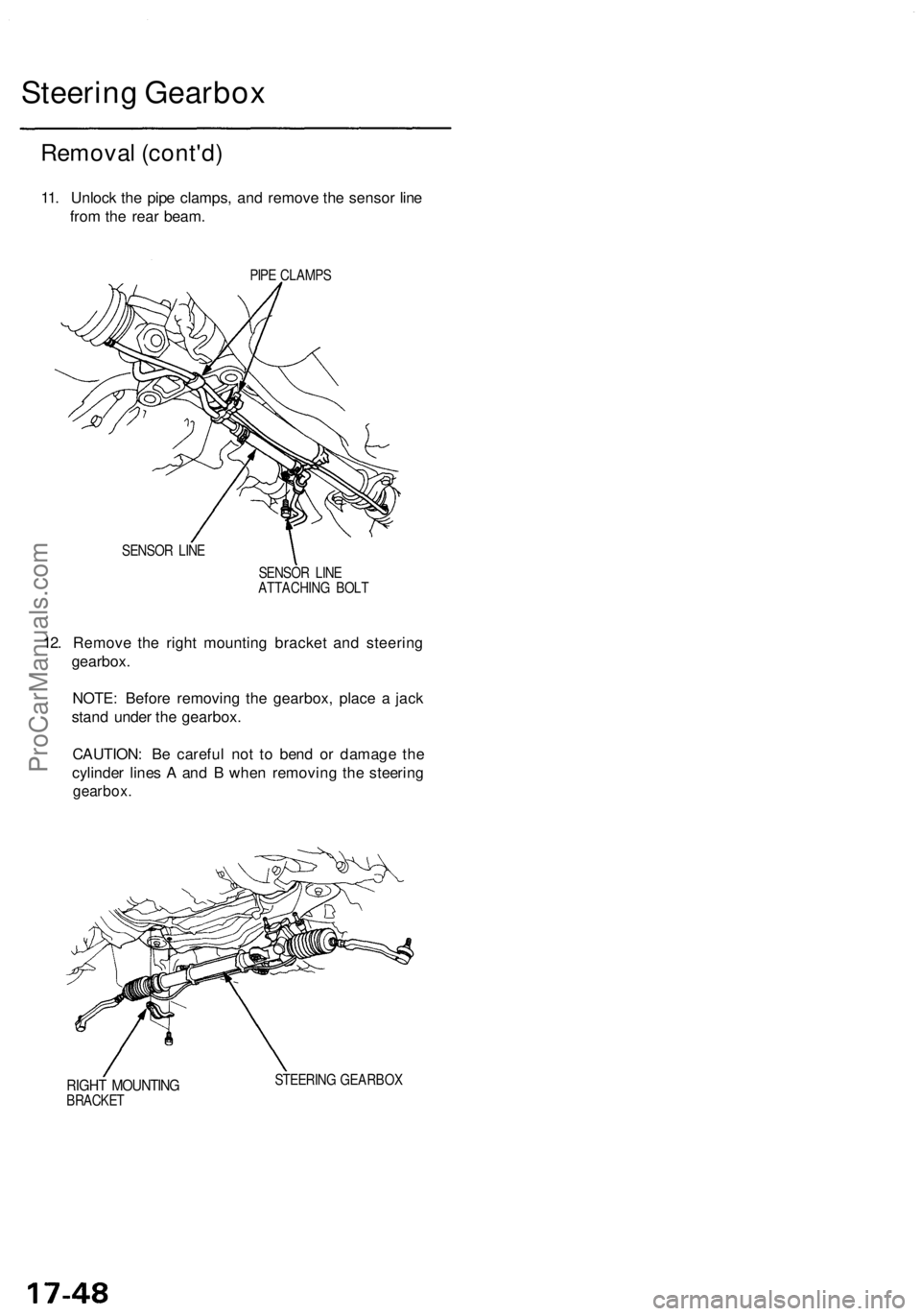
11. Unloc k th e pip e clamps , an d remov e th e senso r lin e
fro m th e rea r beam .
PIPE CLAMP S
SENSO R LIN E
SENSOR LIN E
ATTACHIN G BOL T
12. Remov e th e righ t mountin g bracke t an d steerin g
gearbox .
NOTE : Befor e removin g th e gearbox , plac e a jac k
stan d unde r th e gearbox .
CAUTION : B e carefu l no t t o ben d o r damag e th e
cylinde r line s A an d B whe n removin g th e steerin g
gearbox .
RIGHT MOUNTIN GBRACKET STEERIN
G GEARBO X
ProCarManuals.com
Page 1193 of 1771
Disassembly
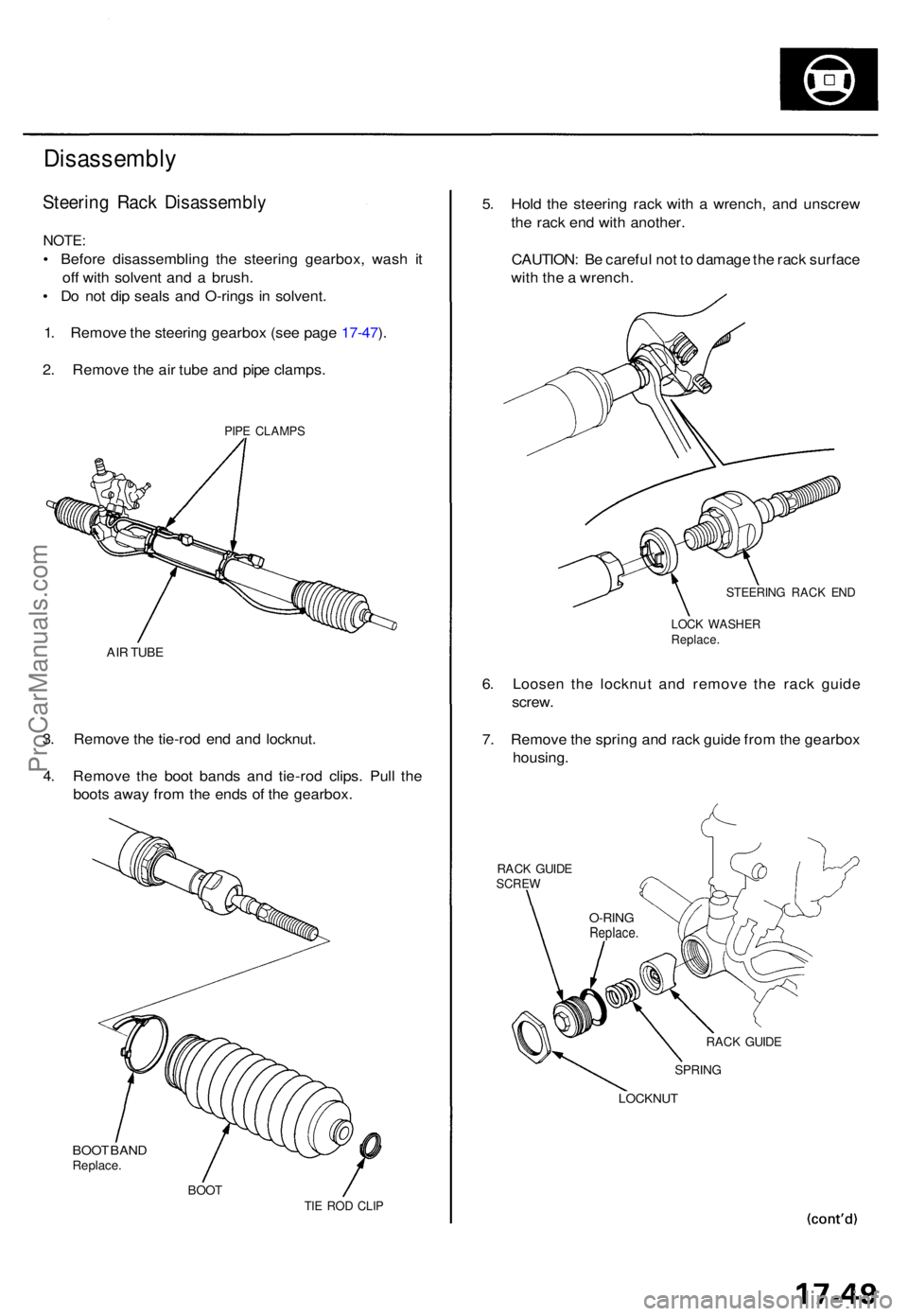
Steering Rac k Disassembl y
NOTE:
• Befor e disassemblin g th e steerin g gearbox , was h i t
of f wit h solven t an d a brush .
• D o no t di p seal s an d O-ring s i n solvent .
1 . Remov e th e steerin g gearbo x (se e pag e 17-47 ).
2 . Remov e th e ai r tub e an d pip e clamps .
PIPE CLAMP S
AIR TUB E
3. Remov e th e tie-ro d en d an d locknut .
4 . Remov e th e boo t band s an d tie-ro d clips . Pul l th e
boot s awa y fro m th e end s o f th e gearbox.
BOO T BAN DReplace .
BOOTTIE RO D CLI P
5. Hol d th e steerin g rac k wit h a wrench , an d unscre w
th e rac k en d wit h another .
CAUTION : B e carefu l no t t o damag e th e rac k surfac e
wit h th e a wrench .
STEERIN G RAC K EN D
LOC K WASHE RReplace.
6. Loose n th e locknu t an d remov e th e rac k guid e
screw .
7 . Remov e th e sprin g an d rac k guid e fro m th e gearbo x
housing .
RACK GUID ESCRE W
RACK GUID E
SPRIN G
LOCKNU T
O-RINGReplace .
ProCarManuals.com
Page 1194 of 1771
Steering Gearbo x
Disassembl y (cont'd )
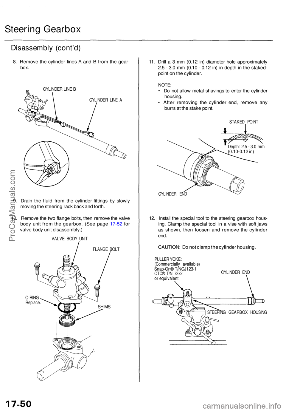
8. Remov e th e cylinde r line s A an d B fro m th e gear -
box.
CYLINDE R LIN E B
CYLINDE R LIN E A
9. Drai n th e flui d fro m th e cylinde r fitting s b y slowl y
movin g th e steerin g rac k bac k an d forth .
10 . Remov e th e tw o flang e bolts , the n remov e th e valv e
bod y uni t fro m th e gearbox . (Se e pag e 17-5 2 fo r
valv e bod y uni t disassembly. )
VALVE BOD Y UNI T
FLANG E BOL T
O-RIN G
Replace .
11. Dril l a 3 mm (0.1 2 in ) diamete r hol e approximatel y
2. 5 - 3. 0 m m (0.1 0 - 0.1 2 in ) i n dept h in th e staked -
poin t o n th e cylinder .
NOTE:
• D o no t allo w meta l shaving s t o ente r th e cylinde r
housing .
• Afte r removin g th e cylinde r end , remov e an y
burr s a t th e stak e point .
STAKE D POIN T
CYLINDE R EN D
12. Instal l th e specia l too l t o th e steerin g gearbo x hous -
ing . Clam p th e specia l too l i n a vis e wit h sof t jaw s
a s shown , the n loose n an d remov e th e cylinde r
end.
CAUTION : D o no t clam p th e cylinde r housing .
PULLER YOKE :
(Commerciall y available )
Snap-On® T/NCJ123- 1OTC® T/ N 737 2or equivalen t
CYLINDER EN D
STEERIN G GEARBO X HOUSIN G
SHIMS
Depth : 2. 5 - 3. 0 m m(0.10-0.1 2 in )
ProCarManuals.com
Page 1195 of 1771
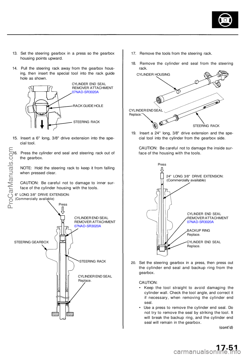
13. Se t th e steerin g gearbo x i n a pres s s o th e gearbo x
housing point s upward .
14. Pul l th e steerin g rac k awa y fro m th e gearbo x hous -
ing , the n inser t th e specia l too l int o th e rac k guid e
hol e a s shown .
CYLINDE R EN D SEA LREMOVE R ATTACHMEN T
07NA D-SR3020 A
RAC K GUID E HOL E
STEERIN G RAC K
15. Inser t a 6 " long , 3/8 " driv e extensio n int o th e spe -
cial tool .
16. Pres s th e cylinde r en d sea l an d steerin g rac k ou t o f
th e gearbox .
NOTE : Hol d th e steerin g rac k t o kee p i t fro m fallin g
whe n presse d clear .
CAUTION : B e carefu l no t t o damag e t o inne r sur -
fac e o f th e cylinde r housin g wit h th e tools .
6" LON G 3/8 " DRIV E EXTENSION :(Commerciall y available )
Press
CYLINDE R EN D SEA L
REMOVE R ATTACHMEN T
07NA D-SR3020 A
STEERIN G GEARBO X
STEERING RAC K
CYLINDE R EN D SEA LReplace .
17. Remov e th e tool s fro m th e steerin g rack .
18 . Remov e th e cylinde r en d sea l fro m th e steerin g
rack.
CYLINDE R HOUSIN G
CYLINDE R EN D SEA L
Replace. "
STEERIN G RAC K
19. Inser t a 24 " long , 3/8 " driv e extensio n an d th e spe -
cia l too l int o th e cylinde r fro m th e gearbo x side .
CAUTION : B e carefu l no t t o damag e th e insid e sur -
fac e o f th e housin g wit h th e tools .
Press
24" LON G 3/8 " DRIV E EXTENSION :(Commercially available )
20.
CYLINDE R EN D SEA LREMOVE R ATTACHMEN T
07NA D-SR3020 A
BACKU P RIN GReplace .
CYLINDE R EN D SEA LReplace .
Set th e steerin g gearbo x i n a press , the n pres s ou t
the cylinde r en d sea l an d backu p rin g fro m th e
gearbox .
CAUTION :
• Kee p th e too l straigh t t o avoi d damagin g th e
cylinde r wall . Chec k th e too l angle , an d correc t i t
i f necessary , whe n removin g th e cylinde r en d
seal .
• Us e a pres s t o remov e th e cylinde r en d seal . D o
no t tr y t o remov e th e sea l b y strikin g th e tool . I t
wil l brea k th e backu p ring , an d th e cylinde r en d
sea l wil l remai n in th e gearbox .
ProCarManuals.com