1994 JEEP CHEROKEE front
[x] Cancel search: frontPage 1653 of 1784
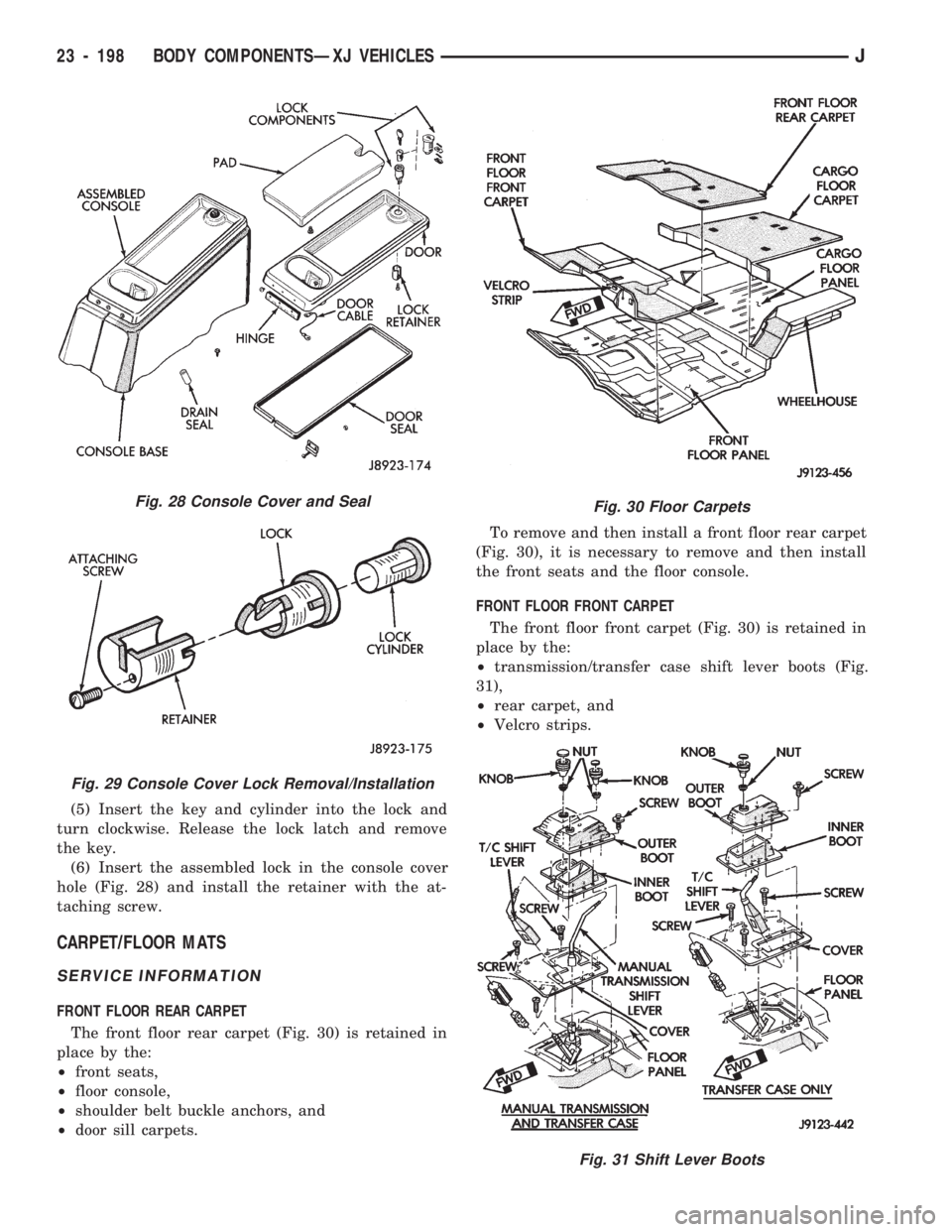
(5) Insert the key and cylinder into the lock and
turn clockwise. Release the lock latch and remove
the key.
(6) Insert the assembled lock in the console cover
hole (Fig. 28) and install the retainer with the at-
taching screw.
CARPET/FLOOR MATS
SERVICE INFORMATION
FRONT FLOOR REAR CARPET
The front floor rear carpet (Fig. 30) is retained in
place by the:
²front seats,
²floor console,
²shoulder belt buckle anchors, and
²door sill carpets.To remove and then install a front floor rear carpet
(Fig. 30), it is necessary to remove and then install
the front seats and the floor console.
FRONT FLOOR FRONT CARPET
The front floor front carpet (Fig. 30) is retained in
place by the:
²transmission/transfer case shift lever boots (Fig.
31),
²rear carpet, and
²Velcro strips.
Fig. 28 Console Cover and Seal
Fig. 29 Console Cover Lock Removal/Installation
Fig. 30 Floor Carpets
Fig. 31 Shift Lever Boots
23 - 198 BODY COMPONENTSÐXJ VEHICLESJ
Page 1654 of 1784
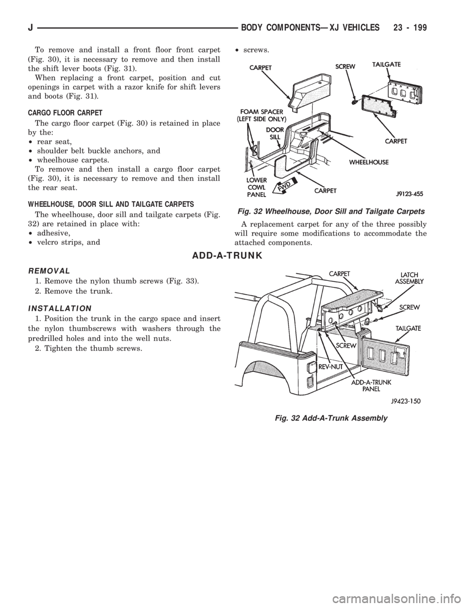
To remove and install a front floor front carpet
(Fig. 30), it is necessary to remove and then install
the shift lever boots (Fig. 31).
When replacing a front carpet, position and cut
openings in carpet with a razor knife for shift levers
and boots (Fig. 31).
CARGO FLOOR CARPET
The cargo floor carpet (Fig. 30) is retained in place
by the:
²rear seat,
²shoulder belt buckle anchors, and
²wheelhouse carpets.
To remove and then install a cargo floor carpet
(Fig. 30), it is necessary to remove and then install
the rear seat.
WHEELHOUSE, DOOR SILL AND TAILGATE CARPETS
The wheelhouse, door sill and tailgate carpets (Fig.
32) are retained in place with:
²adhesive,
²velcro strips, and²screws.
A replacement carpet for any of the three possibly
will require some modifications to accommodate the
attached components.
ADD-A-TRUNK
REMOVAL
1. Remove the nylon thumb screws (Fig. 33).
2. Remove the trunk.
INSTALLATION
1. Position the trunk in the cargo space and insert
the nylon thumbscrews with washers through the
predrilled holes and into the well nuts.
2. Tighten the thumb screws.
Fig. 32 Wheelhouse, Door Sill and Tailgate Carpets
Fig. 32 Add-A-Trunk Assembly
JBODY COMPONENTSÐXJ VEHICLES 23 - 199
Page 1657 of 1784
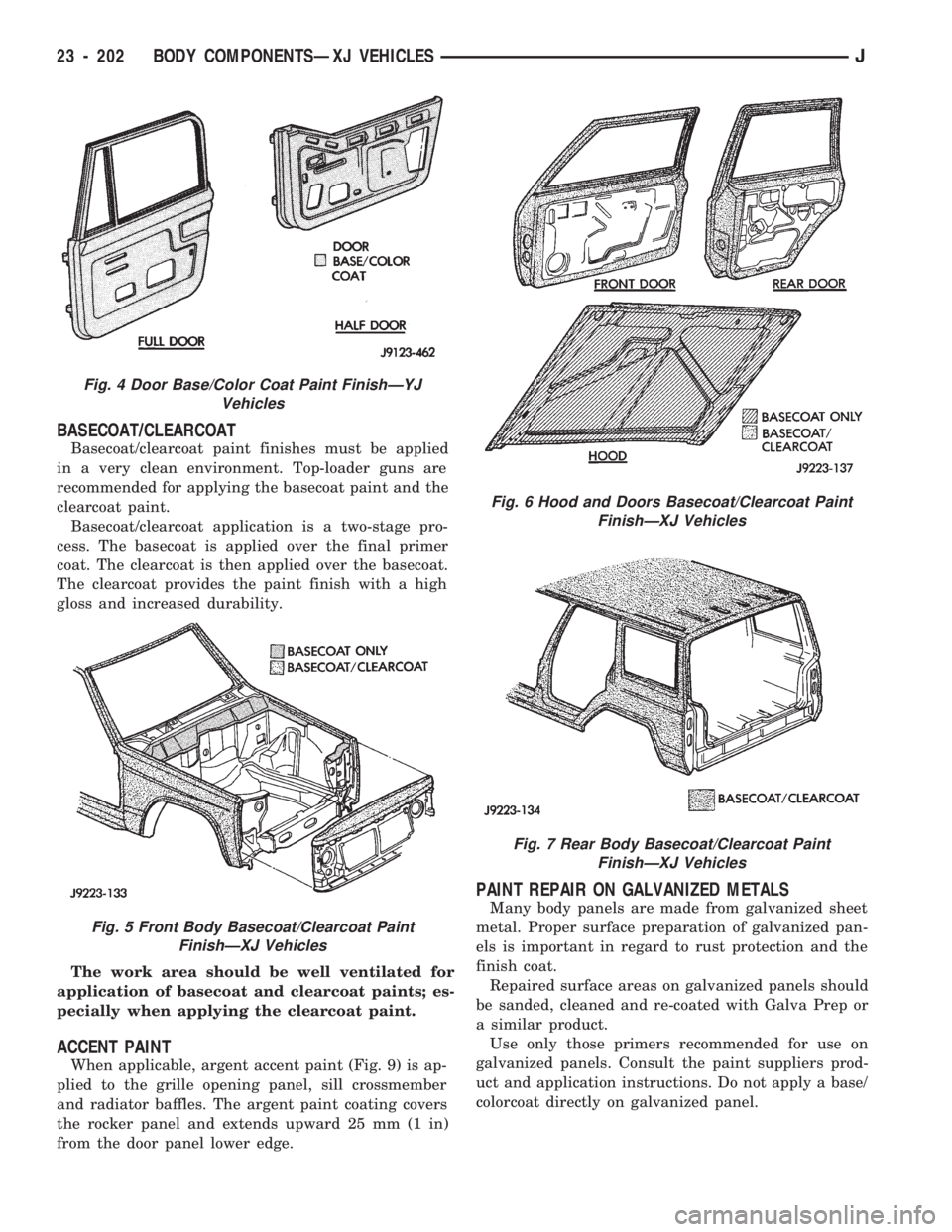
BASECOAT/CLEARCOAT
Basecoat/clearcoat paint finishes must be applied
in a very clean environment. Top-loader guns are
recommended for applying the basecoat paint and the
clearcoat paint.
Basecoat/clearcoat application is a two-stage pro-
cess. The basecoat is applied over the final primer
coat. The clearcoat is then applied over the basecoat.
The clearcoat provides the paint finish with a high
gloss and increased durability.
The work area should be well ventilated for
application of basecoat and clearcoat paints; es-
pecially when applying the clearcoat paint.
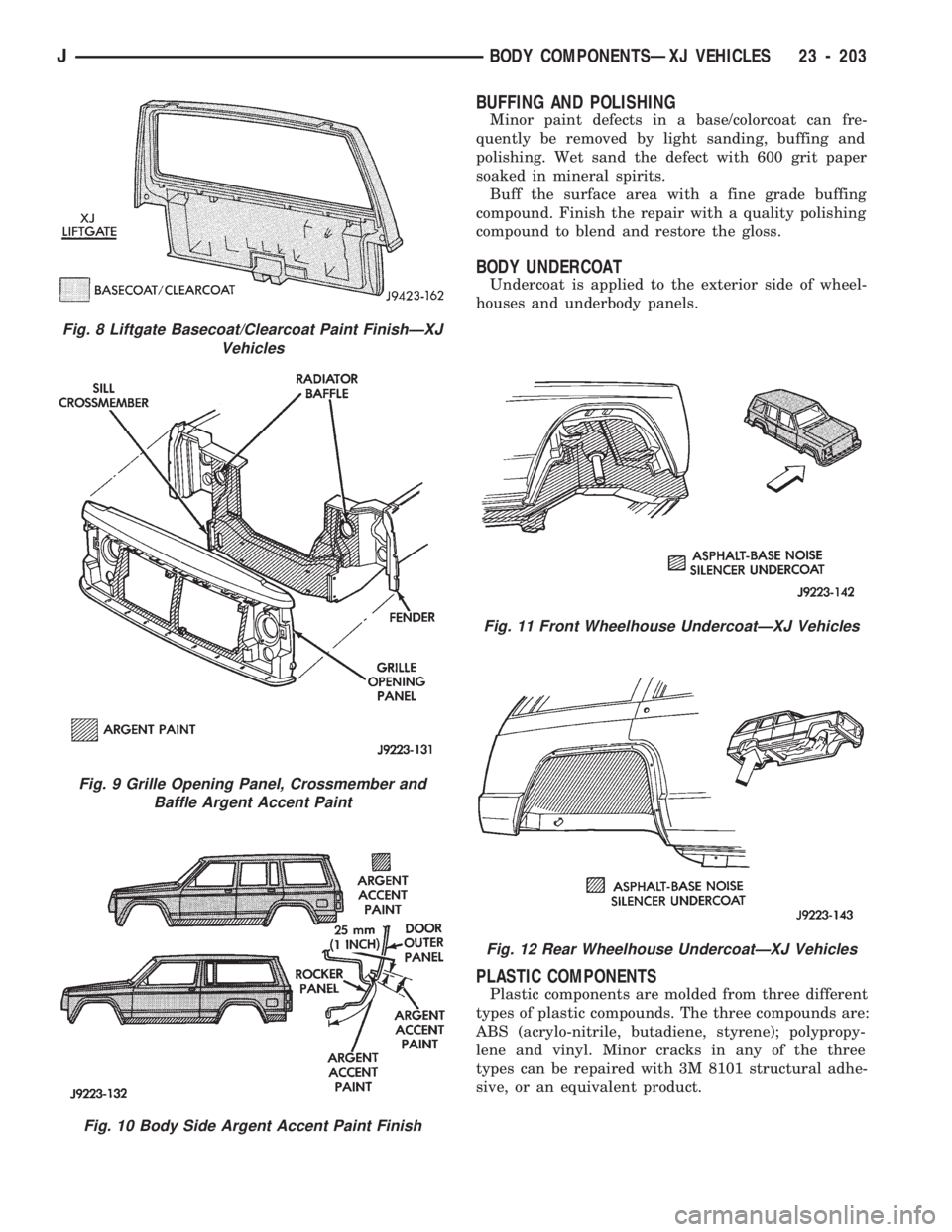
ACCENT PAINT
When applicable, argent accent paint (Fig. 9) is ap-
plied to the grille opening panel, sill crossmember
and radiator baffles. The argent paint coating covers
the rocker panel and extends upward 25 mm (1 in)
from the door panel lower edge.
PAINT REPAIR ON GALVANIZED METALS
Many body panels are made from galvanized sheet
metal. Proper surface preparation of galvanized pan-
els is important in regard to rust protection and the
finish coat.
Repaired surface areas on galvanized panels should
be sanded, cleaned and re-coated with Galva Prep or
a similar product.
Use only those primers recommended for use on
galvanized panels. Consult the paint suppliers prod-
uct and application instructions. Do not apply a base/
colorcoat directly on galvanized panel.
Fig. 4 Door Base/Color Coat Paint FinishÐYJ
Vehicles
Fig. 5 Front Body Basecoat/Clearcoat Paint
FinishÐXJ Vehicles
Fig. 6 Hood and Doors Basecoat/Clearcoat Paint
FinishÐXJ Vehicles
Fig. 7 Rear Body Basecoat/Clearcoat Paint
FinishÐXJ Vehicles
23 - 202 BODY COMPONENTSÐXJ VEHICLESJ
Page 1658 of 1784
BUFFING AND POLISHING
Minor paint defects in a base/colorcoat can fre-
quently be removed by light sanding, buffing and
polishing. Wet sand the defect with 600 grit paper
soaked in mineral spirits.
Buff the surface area with a fine grade buffing
compound. Finish the repair with a quality polishing
compound to blend and restore the gloss.
BODY UNDERCOAT
Undercoat is applied to the exterior side of wheel-
houses and underbody panels.
PLASTIC COMPONENTS
Plastic components are molded from three different
types of plastic compounds. The three compounds are:
ABS (acrylo-nitrile, butadiene, styrene); polypropy-
lene and vinyl. Minor cracks in any of the three
types can be repaired with 3M 8101 structural adhe-
sive, or an equivalent product.
Fig. 8 Liftgate Basecoat/Clearcoat Paint FinishÐXJ
Vehicles
Fig. 9 Grille Opening Panel, Crossmember and
Baffle Argent Accent Paint
Fig. 10 Body Side Argent Accent Paint Finish
Fig. 11 Front Wheelhouse UndercoatÐXJ Vehicles
Fig. 12 Rear Wheelhouse UndercoatÐXJ Vehicles
JBODY COMPONENTSÐXJ VEHICLES 23 - 203
Page 1666 of 1784
MANIFOLD
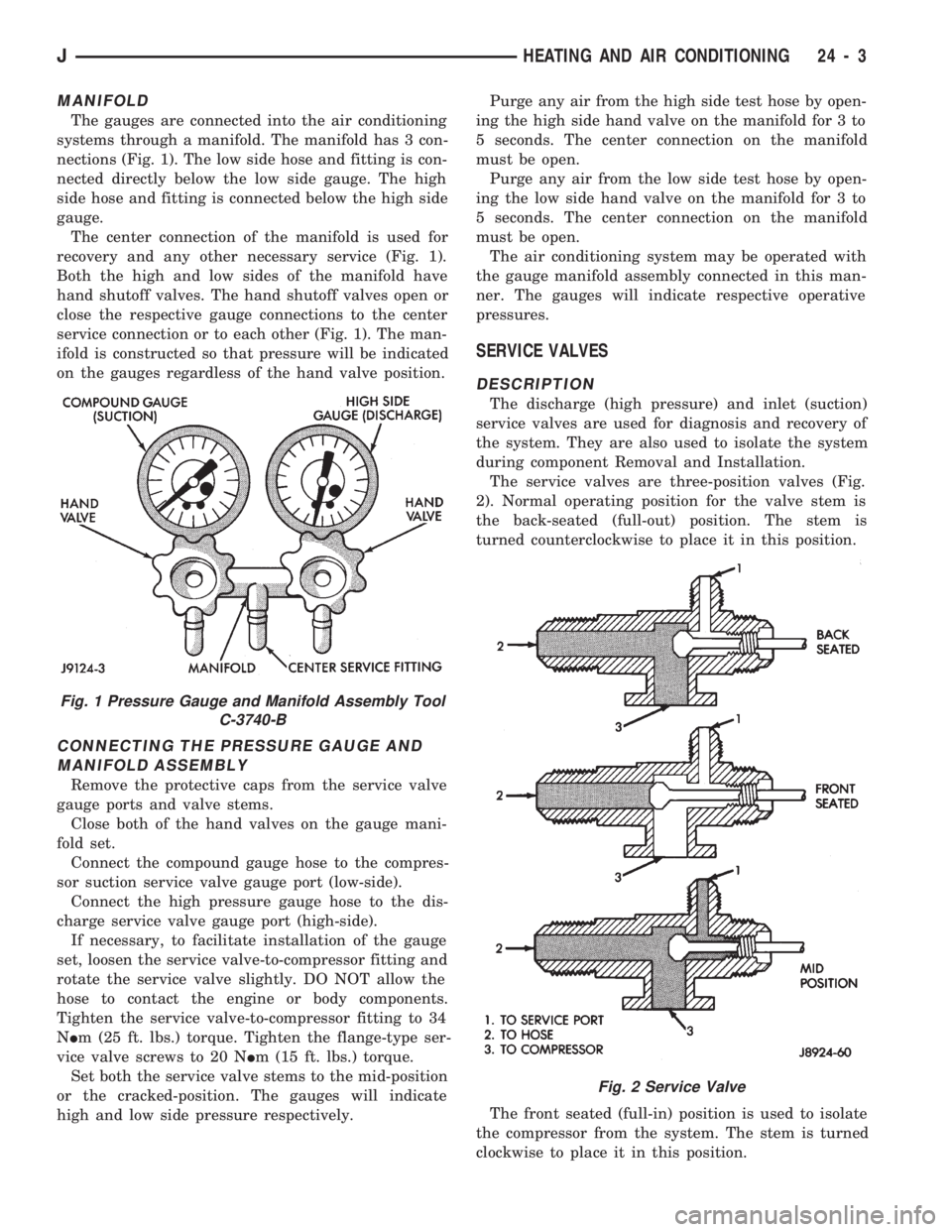
The gauges are connected into the air conditioning
systems through a manifold. The manifold has 3 con-
nections (Fig. 1). The low side hose and fitting is con-
nected directly below the low side gauge. The high
side hose and fitting is connected below the high side
gauge.
The center connection of the manifold is used for
recovery and any other necessary service (Fig. 1).
Both the high and low sides of the manifold have
hand shutoff valves. The hand shutoff valves open or
close the respective gauge connections to the center
service connection or to each other (Fig. 1). The man-
ifold is constructed so that pressure will be indicated
on the gauges regardless of the hand valve position.
CONNECTING THE PRESSURE GAUGE AND
MANIFOLD ASSEMBLY
Remove the protective caps from the service valve
gauge ports and valve stems.
Close both of the hand valves on the gauge mani-
fold set.
Connect the compound gauge hose to the compres-
sor suction service valve gauge port (low-side).
Connect the high pressure gauge hose to the dis-
charge service valve gauge port (high-side).
If necessary, to facilitate installation of the gauge
set, loosen the service valve-to-compressor fitting and
rotate the service valve slightly. DO NOT allow the
hose to contact the engine or body components.
Tighten the service valve-to-compressor fitting to 34
NIm (25 ft. lbs.) torque. Tighten the flange-type ser-
vice valve screws to 20 NIm (15 ft. lbs.) torque.
Set both the service valve stems to the mid-position
or the cracked-position. The gauges will indicate
high and low side pressure respectively.Purge any air from the high side test hose by open-
ing the high side hand valve on the manifold for 3 to
5 seconds. The center connection on the manifold
must be open.
Purge any air from the low side test hose by open-
ing the low side hand valve on the manifold for 3 to
5 seconds. The center connection on the manifold
must be open.
The air conditioning system may be operated with
the gauge manifold assembly connected in this man-
ner. The gauges will indicate respective operative
pressures.
SERVICE VALVES
DESCRIPTION
The discharge (high pressure) and inlet (suction)
service valves are used for diagnosis and recovery of
the system. They are also used to isolate the system
during component Removal and Installation.
The service valves are three-position valves (Fig.
2). Normal operating position for the valve stem is
the back-seated (full-out) position. The stem is
turned counterclockwise to place it in this position.
The front seated (full-in) position is used to isolate
the compressor from the system. The stem is turned
clockwise to place it in this position.
Fig. 1 Pressure Gauge and Manifold Assembly Tool
C-3740-B
Fig. 2 Service Valve
JHEATING AND AIR CONDITIONING 24 - 3
Page 1667 of 1784
In the mid-position the gauge port is open. This po-
sition is used for pressure testing and for recovery of
the system.
DISCHARGE SERVICE VALVE ADAPTERS
On occasion, a service hose may not fit a service
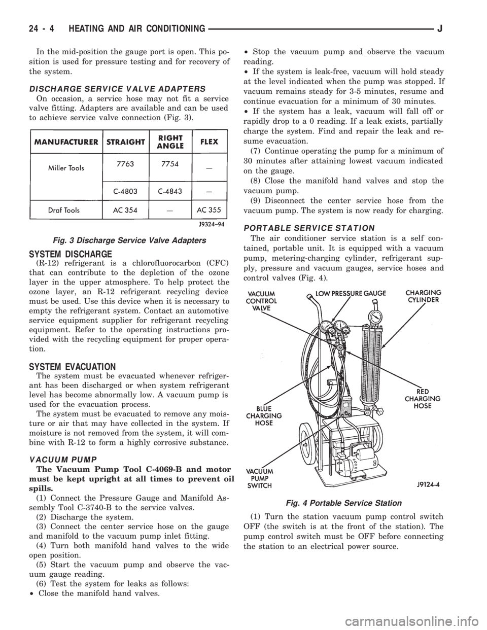
valve fitting. Adapters are available and can be used
to achieve service valve connection (Fig. 3).
SYSTEM DISCHARGE
(R-12) refrigerant is a chlorofluorocarbon (CFC)
that can contribute to the depletion of the ozone
layer in the upper atmosphere. To help protect the
ozone layer, an R-12 refrigerant recycling device
must be used. Use this device when it is necessary to
empty the refrigerant system. Contact an automotive
service equipment supplier for refrigerant recycling
equipment. Refer to the operating instructions pro-
vided with the recycling equipment for proper opera-
tion.
SYSTEM EVACUATION
The system must be evacuated whenever refriger-
ant has been discharged or when system refrigerant
level has become abnormally low. A vacuum pump is
used for the evacuation process.
The system must be evacuated to remove any mois-
ture or air that may have collected in the system. If
moisture is not removed from the system, it will com-
bine with R-12 to form a highly corrosive substance.
VACUUM PUMP
The Vacuum Pump Tool C-4069-B and motor
must be kept upright at all times to prevent oil
spills.
(1) Connect the Pressure Gauge and Manifold As-
sembly Tool C-3740-B to the service valves.
(2) Discharge the system.
(3) Connect the center service hose on the gauge
and manifold to the vacuum pump inlet fitting.
(4) Turn both manifold hand valves to the wide
open position.
(5) Start the vacuum pump and observe the vac-
uum gauge reading.
(6) Test the system for leaks as follows:
²Close the manifold hand valves.²Stop the vacuum pump and observe the vacuum
reading.
²If the system is leak-free, vacuum will hold steady
at the level indicated when the pump was stopped. If
vacuum remains steady for 3-5 minutes, resume and
continue evacuation for a minimum of 30 minutes.
²If the system has a leak, vacuum will fall off or
rapidly drop to a 0 reading. If a leak exists, partially
charge the system. Find and repair the leak and re-
sume evacuation.
(7) Continue operating the pump for a minimum of
30 minutes after attaining lowest vacuum indicated
on the gauge.
(8) Close the manifold hand valves and stop the
vacuum pump.
(9) Disconnect the center service hose from the
vacuum pump. The system is now ready for charging.
PORTABLE SERVICE STATION
The air conditioner service station is a self con-
tained, portable unit. It is equipped with a vacuum
pump, metering-charging cylinder, refrigerant sup-
ply, pressure and vacuum gauges, service hoses and
control valves (Fig. 4).
(1) Turn the station vacuum pump control switch
OFF (the switch is at the front of the station). The
pump control switch must be OFF before connecting
the station to an electrical power source.Fig. 3 Discharge Service Valve Adapters
Fig. 4 Portable Service Station
24 - 4 HEATING AND AIR CONDITIONINGJ
Page 1669 of 1784
(18) Disconnect the charging hoses from the ser-
vice valves.
COMPRESSOR OIL LEVEL
The compressor oil level must be checked and ad-
justed if the system has been discharged rapidly, or
when a component has been replaced. If a replace-
ment compressor is being installed, it must be filled
with new compressor oil (Suniso 5GS, or equivalent).
The normal quantity of oil required for the com-
pressor and entire system is 136 ml (4.6 fluid oz.) for
SD 709 compressor. DO NOT overfill the compressor.
Excessive amounts of oil in the system will hinder
compressor operation and reduce A/C performance.
CAUTION: The compressor is a high speed unit.
Satisfactory operation is dependent on sufficient lu-
brication; however, excess oil will hinder A/C per-
formance.
Two oil level checking procedures are necessary.
Use Procedure (A) when the compressor is being re-
placed and the system was discharged properly (no
oil loss). Use Procedure (B) for routine maintenance
or when checking oil level after replacing a system
component.
In cases where rapid loss of refrigerant and oil
occurred, the system must be evacuated and
purged. Then the compressor must be filled with
the necessary amount of oil to fill the entire sys-
tem.
PROCEDURE A
(1) Remove the oil filler plug, discharge cap and
suction port caps from the original and replacement
compressor.
(2) Use a clean container to drain the oil from the
replacement compressor. Drain the oil through the
oil filler plug hole, the discharge and suction. Then
rotate clutch front plate several times to push the oil
on cylinder out to discharge chamber of cylinder
head and drain the oil from discharge port.
(3) Drain the oil from the original compressor into
a measuring cup or graduated beaker in the same
way as Step 2. Note the amount of oil drained.
(4) Fill the replacement compressor with the same
amount of oil drained from the original compressor
plus 30 ml (1 fluid oz.).
FOR EXAMPLE:ÐIf the old compressor contained
103.5 ml (3.5 fluid oz.) of oil, fill the replacement
compressor with a total of 133 ml (4.5 fluid oz.) of oil.
PROCEDURE B
(1) Start the engine and operate the engine at idle.
(2) Operate the air conditioning system for 10 min-
utes to return the maximum amount of oil in the sys-
tem to the compressor.(3) Stop the engine and disconnect the magnetic
clutch feed wire.
(4) Front-seat the discharge and suction service
valves.
(5) Determine the mounting angle.
(a) Position an Angle Gauge across the flat sur-
faces of the front mounting ears.
(b) Center the bubble.
(c) Read the mounting angle to the closest de-
gree.
(d) These vehicles should have 0É mounting an-
gle.
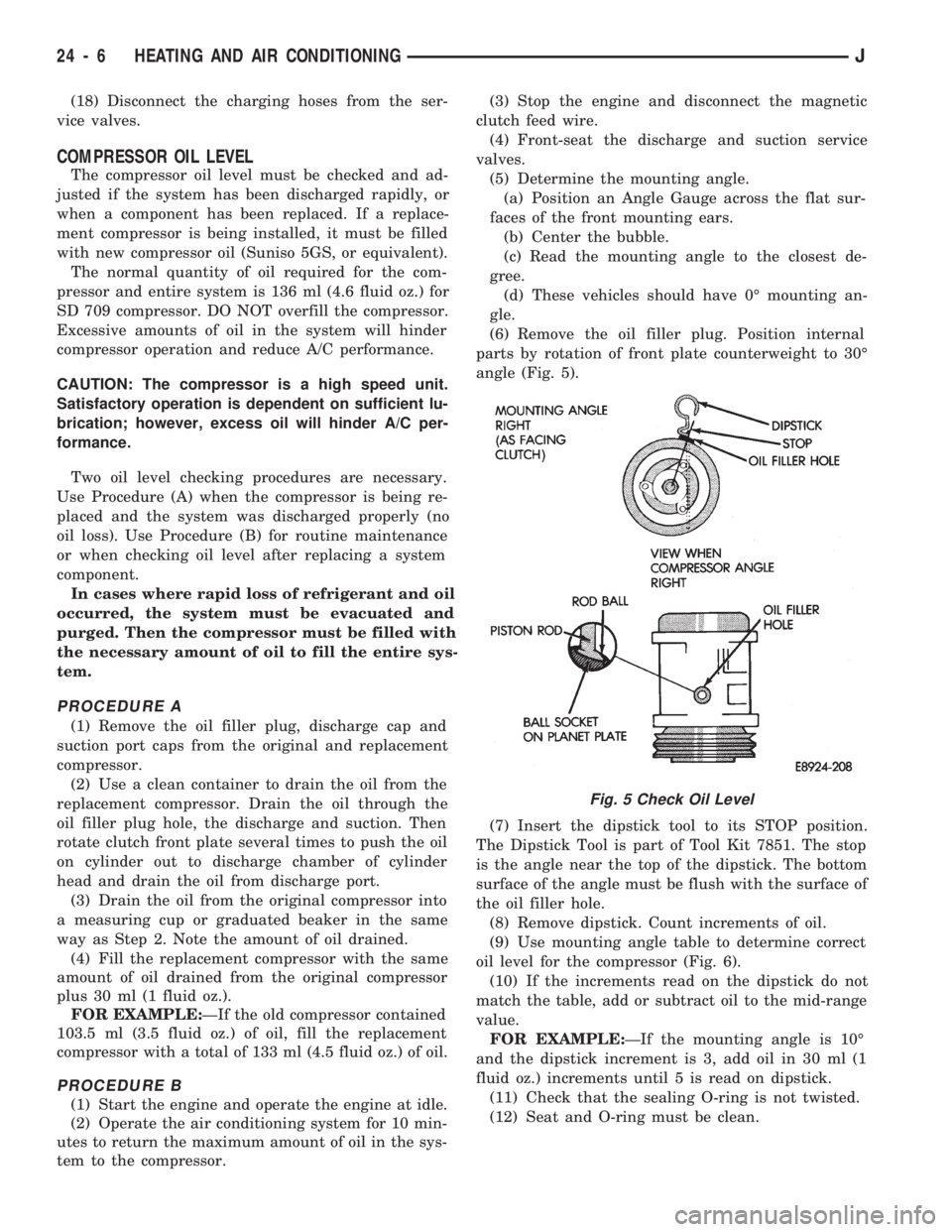
(6) Remove the oil filler plug. Position internal
parts by rotation of front plate counterweight to 30É
angle (Fig. 5).
(7) Insert the dipstick tool to its STOP position.
The Dipstick Tool is part of Tool Kit 7851. The stop
is the angle near the top of the dipstick. The bottom
surface of the angle must be flush with the surface of
the oil filler hole.
(8) Remove dipstick. Count increments of oil.
(9) Use mounting angle table to determine correct
oil level for the compressor (Fig. 6).
(10) If the increments read on the dipstick do not
match the table, add or subtract oil to the mid-range
value.
FOR EXAMPLE:ÐIf the mounting angle is 10É
and the dipstick increment is 3, add oil in 30 ml (1
fluid oz.) increments until 5 is read on dipstick.
(11) Check that the sealing O-ring is not twisted.
(12) Seat and O-ring must be clean.
Fig. 5 Check Oil Level
24 - 6 HEATING AND AIR CONDITIONINGJ
Page 1680 of 1784
COMPRESSOR OVERHAUL
INDEX
page page
Compressor............................. 17
Compressor Isolation...................... 17
Description............................. 17Magnetic Clutch......................... 18
Purging Compressor of Air................. 17
DESCRIPTION
The A/C system uses a Sanden compressor. This
compressor is a 7 piston design. Designated the SD-
709, the compressor is mounted on the front right
side of the engine and is driven by a serpentine belt.
System lubrication is provided by 135cc615cc (4.6
cu. in.60.5 cu. in.) of 500 viscosity refrigerant oil.
The clutch used on the compressor consists of 3 ba-
sic components: the pulley, front plate and the field
coil. The pulley and field coil are attached to the
front head of the compressor with tapered snap rings.
The hub is keyed to the compressor shaft and is re-
tained on the shaft with a self-locking nut. Special
service tools are required to remove and install the
clutch plate on the compressor shaft.
COMPRESSOR ISOLATION
It is not necessary to discharge the system for com-
pressor removal. The compressor can be isolated from
the remainder of the system and eliminate the need
for recharging when performing compressor service.
(1) Connect pressure gauge and manifold.
(2) Close both gauge hand valves.
(3) Mid-position both service valves.
WARNING: USE EXTREME CAUTION WHEN THE
ENGINE IS OPERATING. DO NOT STAND IN A DI-
RECT LINE WITH THE FAN. DO NOT PUT YOUR
HANDS NEAR THE PULLEYS, BELTS OR FAN. DO
NOT WEAR LOOSE CLOTHING.
(4) Start the engine and operate the air condition-
ing system.
(5) Turn the suction service valve slowly clockwise
toward the front seated position.
(6) When pressure drops to zero, stop the engine
and compressor and quickly finish front-seating the
suction service valve.
(7) Front-seat the discharge service valve.
(8) Loosen the oil level check plug slowly to re-
lease any internal pressure in the compressor.
The compressor is now isolated from the remainder
of the system.
The service valves can be removed from the com-
pressor.
PURGING COMPRESSOR OF AIR
The compressor must be purged of air whenever it
has been isolated for an oil level check or other ser-
vice procedures without discharging the entire sys-
tem.
(1) Cap the service gauge ports on both of the ser-
vice valves.
(2) Back-seat the suction service valve to allow the
system refrigerant to enter the compressor.
(3) Place the discharge service valve in the mid-po-
sition or cracked-position.
(4) Loosen the discharge service valve gauge port
cap to permit the refrigerant to force any air out of
the compressor.
(5) Back-seat the discharge service valve and
tighten the gauge port cap.
(6) The compressor is now ready for service.
COMPRESSOR
REMOVAL
(1) Isolate the compressor.
(2) Disconnect negative cable from battery.
(3) Disconnect the clutch lead wire.
(4) Remove the discharge and inlet (suction) ser-
vice valves from the compressor. Plug or tape all the
openings.
(5) Remove the serpentine drive belt (refer to
Group 7, Cooling System for the proper procedure).
(6) Remove the bolts and lift the compressor from
the mounting bracket (Figs. 1 and 2).
INSTALLATION
If a replacement compressor is being installed;
check the oil level. Add or subtract oil as neces-
sary and install the magnetic clutch on the com-
pressor.
(1) If the mounting bracket was removed, install
the bracket to the block. Tighten the mounting bolts
to 27 NIm (20 ft. lbs.) torque.
(2) Install the compressor on the mounting
bracket. Tighten the bolts to 27 NIm (20 ft. lbs.)
torque.
(3) Install the serpentine drive belt (refer to Group
7, Cooling System for the proper procedure).
(4) Tighten the serpentine drive belt to the speci-
fied tension.
²New belt tensionÐ800-900 N (180-200 lb-f).
JHEATING AND AIR CONDITIONING 24 - 17