Page 1569 of 1784
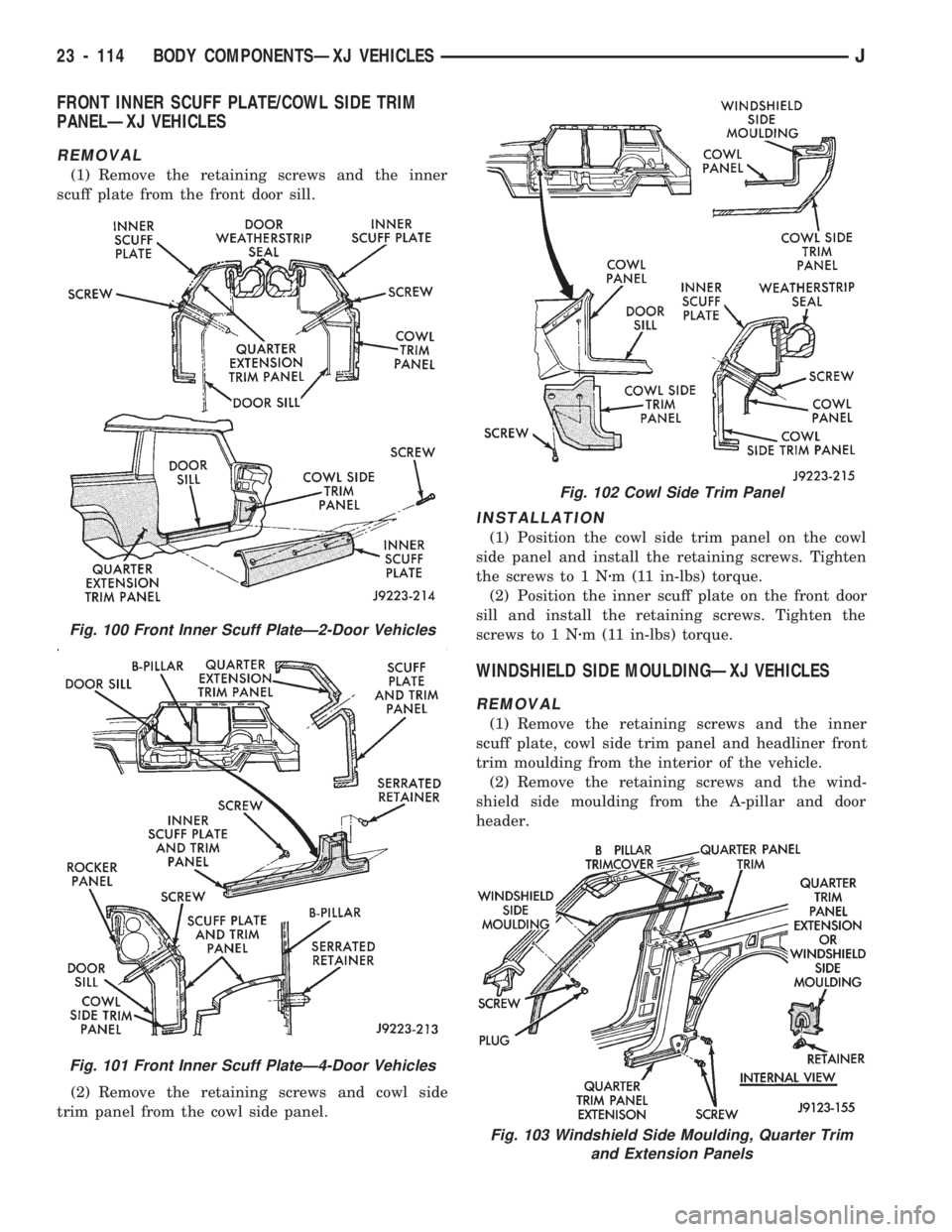
FRONT INNER SCUFF PLATE/COWL SIDE TRIM
PANELÐXJ VEHICLES
REMOVAL
(1) Remove the retaining screws and the inner
scuff plate from the front door sill.
(2) Remove the retaining screws and cowl side
trim panel from the cowl side panel.
INSTALLATION
(1) Position the cowl side trim panel on the cowl
side panel and install the retaining screws. Tighten
the screws to 1 Nzm (11 in-lbs) torque.
(2) Position the inner scuff plate on the front door
sill and install the retaining screws. Tighten the
screws to 1 Nzm (11 in-lbs) torque.
WINDSHIELD SIDE MOULDINGÐXJ VEHICLES
REMOVAL
(1) Remove the retaining screws and the inner
scuff plate, cowl side trim panel and headliner front
trim moulding from the interior of the vehicle.
(2) Remove the retaining screws and the wind-
shield side moulding from the A-pillar and door
header.
Fig. 100 Front Inner Scuff PlateÐ2-Door Vehicles
Fig. 101 Front Inner Scuff PlateÐ4-Door Vehicles
Fig. 102 Cowl Side Trim Panel
Fig. 103 Windshield Side Moulding, Quarter Trim
and Extension Panels
23 - 114 BODY COMPONENTSÐXJ VEHICLESJ
Page 1570 of 1784
INSTALLATION
(1) Position the windshield side moulding on the A-
pillar and door header. Install the retaining screws
and tighten to 1 Nzm (11 in-lbs) torque.
(2) Install the headliner front trim moulding, the
cowl side trim panel and the inner scuff plate in the
interior of the vehicle. Tighten the retaining screw to
1Nzm (11 in-lbs) torque.
QUARTER TRIM PANEL EXTENSIONÐXJ VEHICLES
REMOVAL
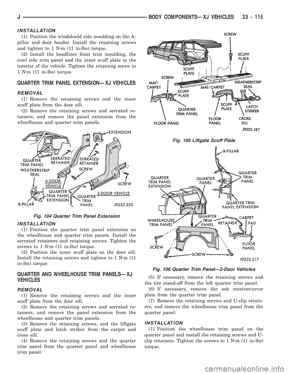
(1) Remove the retaining screws and the inner
scuff plate from the door sill.
(2) Remove the retaining screws and serrated re-
tainers, and remove the panel extension from the
wheelhouse and quarter trim panels.
INSTALLATION
(1) Position the quarter trim panel extension on
the wheelhouse and quarter trim panels. Install the
serrated retainers and retaining screws. Tighten the
screws to 1 Nzm (11 in-lbs) torque.
(2) Position the inner scuff plate on the door sill.
Install the retaining screws and tighten to 1 Nzm(11
in-lbs) torque.
QUARTER AND WHEELHOUSE TRIM PANELSÐXJ
VEHICLES
REMOVAL
(1) Remove the retaining screws and the inner
scuff plate from the door sill.
(2) Remove the retaining screws and serrated re-
tainers, and remove the panel extension from the
wheelhouse and quarter trim panels.
(3) Remove the retaining screws, and the liftgate
scuff plate and latch striker from the carpet and
cross sill.
(4) Remove the retaining screws and the quarter
trim panel from the quarter panel and wheelhouse
trim panel.(5) If necessary, remove the retaining screws and
the tire stand-off from the left quarter trim panel.
(6) If necessary, remove the ash receiver/cover
plate from the quarter trim panel.
(7) Remove the retaining screws and U-clip retain-
ers, and remove the wheelhouse trim panel from the
quarter panel.
INSTALLATION
(1) Position the wheelhouse trim panel on the
quarter panel and install the retaining screws and U-
clip retainers. Tighten the screws to 1 Nzm (11 in-lbs)
torque.
Fig. 105 Liftgate Scuff Plate
Fig. 106 Quarter Trim PanelÐ2-Door Vehicles
Fig. 104 Quarter Trim Panel Extension
JBODY COMPONENTSÐXJ VEHICLES 23 - 115
Page 1574 of 1784
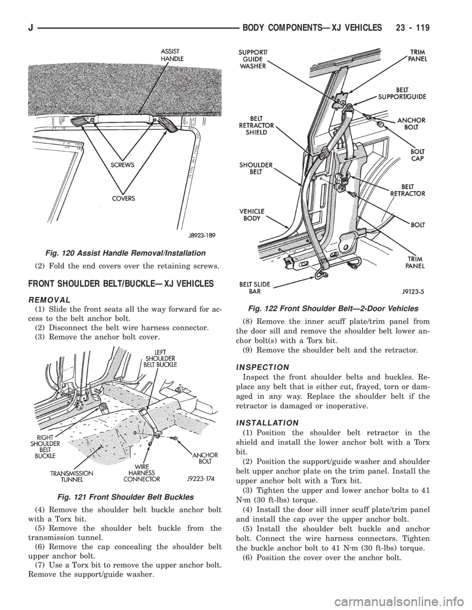
(2) Fold the end covers over the retaining screws.
FRONT SHOULDER BELT/BUCKLEÐXJ VEHICLES
REMOVAL
(1) Slide the front seats all the way forward for ac-
cess to the belt anchor bolt.
(2) Disconnect the belt wire harness connector.
(3) Remove the anchor bolt cover.
(4) Remove the shoulder belt buckle anchor bolt
with a Torx bit.
(5) Remove the shoulder belt buckle from the
transmission tunnel.
(6) Remove the cap concealing the shoulder belt
upper anchor bolt.
(7) Use a Torx bit to remove the upper anchor bolt.
Remove the support/guide washer.(8) Remove the inner scuff plate/trim panel from
the door sill and remove the shoulder belt lower an-
chor bolt(s) with a Torx bit.
(9) Remove the shoulder belt and the retractor.
INSPECTION
Inspect the front shoulder belts and buckles. Re-
place any belt that is either cut, frayed, torn or dam-
aged in any way. Replace the shoulder belt if the
retractor is damaged or inoperative.
INSTALLATION
(1) Position the shoulder belt retractor in the
shield and install the lower anchor bolt with a Torx
bit.
(2) Position the support/guide washer and shoulder
belt upper anchor plate on the trim panel. Install the
upper anchor bolt with a Torx bit.
(3) Tighten the upper and lower anchor bolts to 41
Nzm (30 ft-lbs) torque.
(4) Install the door sill inner scuff plate/trim panel
and install the cap over the upper anchor bolt.
(5) Install the shoulder belt buckle and anchor
bolt. Connect the wire harness connectors. Tighten
the buckle anchor bolt to 41 Nzm (30 ft-lbs) torque.
(6) Position the cover over the anchor bolt.
Fig. 120 Assist Handle Removal/Installation
Fig. 121 Front Shoulder Belt Buckles
Fig. 122 Front Shoulder BeltÐ2-Door Vehicles
JBODY COMPONENTSÐXJ VEHICLES 23 - 119
Page 1575 of 1784
REAR SHOULDER/LAP BELT/BUCKLEÐXJ VEHICLES
REMOVAL
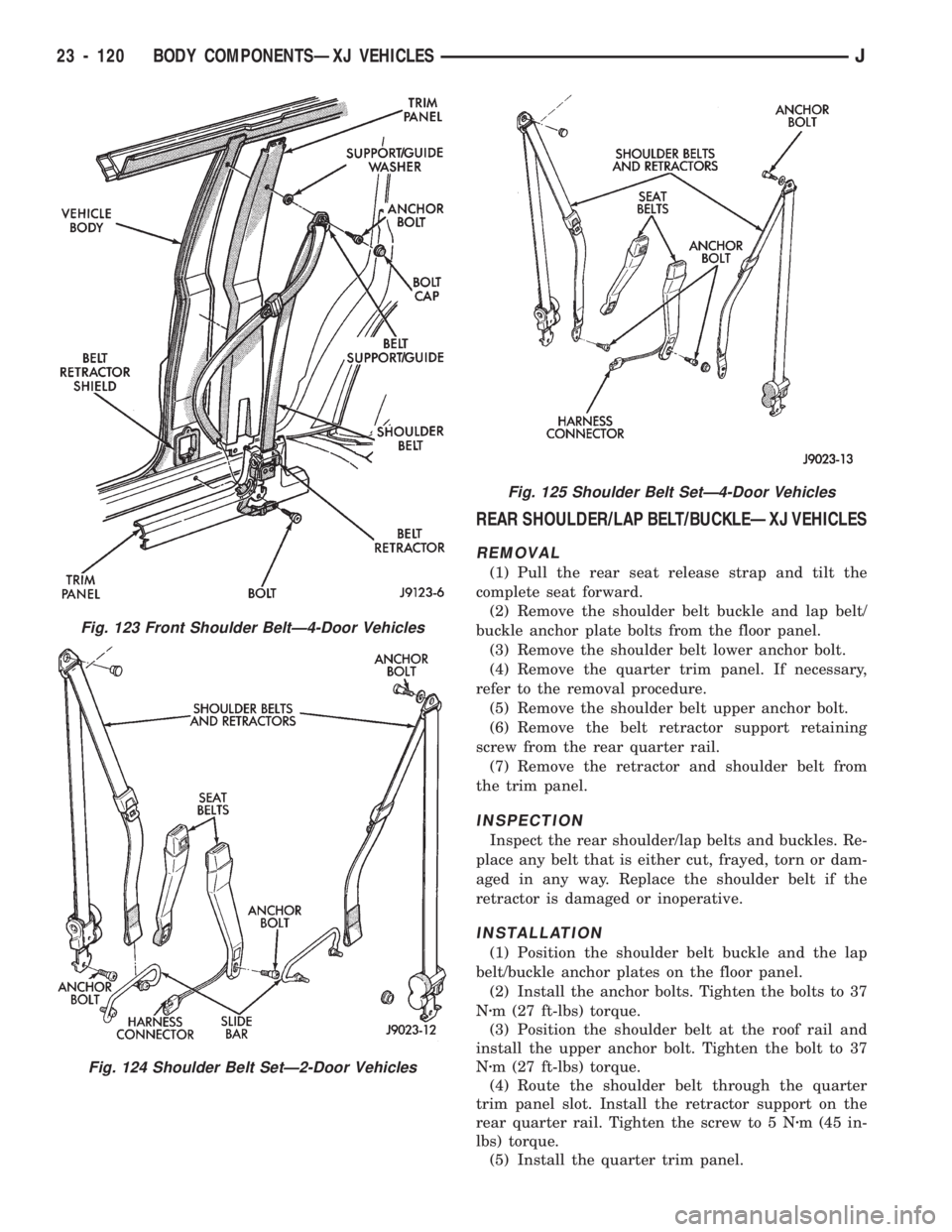
(1) Pull the rear seat release strap and tilt the
complete seat forward.
(2) Remove the shoulder belt buckle and lap belt/
buckle anchor plate bolts from the floor panel.
(3) Remove the shoulder belt lower anchor bolt.
(4) Remove the quarter trim panel. If necessary,
refer to the removal procedure.
(5) Remove the shoulder belt upper anchor bolt.
(6) Remove the belt retractor support retaining
screw from the rear quarter rail.
(7) Remove the retractor and shoulder belt from
the trim panel.
INSPECTION
Inspect the rear shoulder/lap belts and buckles. Re-
place any belt that is either cut, frayed, torn or dam-
aged in any way. Replace the shoulder belt if the
retractor is damaged or inoperative.
INSTALLATION
(1) Position the shoulder belt buckle and the lap
belt/buckle anchor plates on the floor panel.
(2) Install the anchor bolts. Tighten the bolts to 37
Nzm (27 ft-lbs) torque.
(3) Position the shoulder belt at the roof rail and
install the upper anchor bolt. Tighten the bolt to 37
Nzm (27 ft-lbs) torque.
(4) Route the shoulder belt through the quarter
trim panel slot. Install the retractor support on the
rear quarter rail. Tighten the screw to 5 Nzm (45 in-
lbs) torque.
(5) Install the quarter trim panel.
Fig. 123 Front Shoulder BeltÐ4-Door Vehicles
Fig. 124 Shoulder Belt SetÐ2-Door Vehicles
Fig. 125 Shoulder Belt SetÐ4-Door Vehicles
23 - 120 BODY COMPONENTSÐXJ VEHICLESJ
Page 1582 of 1784
²connect the wire harness connector to the outside
mirror remote control switch,
²insert the switch into the console hole, and
²push inward to engage the retaining clips.
(6) Install the shift lever handle/knob.
JACK STORAGEÐXJ VEHICLES
SERVICE INFORMATION
The XJ lift jack and related tools are stored under
the rear seat behind the front passenger's seat. The
jack and tools are attached to the floor panel and
seat cushion crossmember with a retainer and hold-
down bolt.
When necessary, the jack retainer bracket can be
removed from the crossmember by drilling-out the
rivet heads and then removing the rivet bodies with
a punch. Install the retainer bracket with either riv-
ets or bolts and nuts.
Fig. 147 Full Console Removal/Installation
Fig. 148 Air Outlet and Console Floor Air Ducts
Fig. 149 Floor Duct Removal/Installation
Fig. 150 Floor Console Support Brackets
Fig. 151 Jack and Related ToolsÐXJ Vehicles
JBODY COMPONENTSÐXJ VEHICLES 23 - 127
Page 1584 of 1784
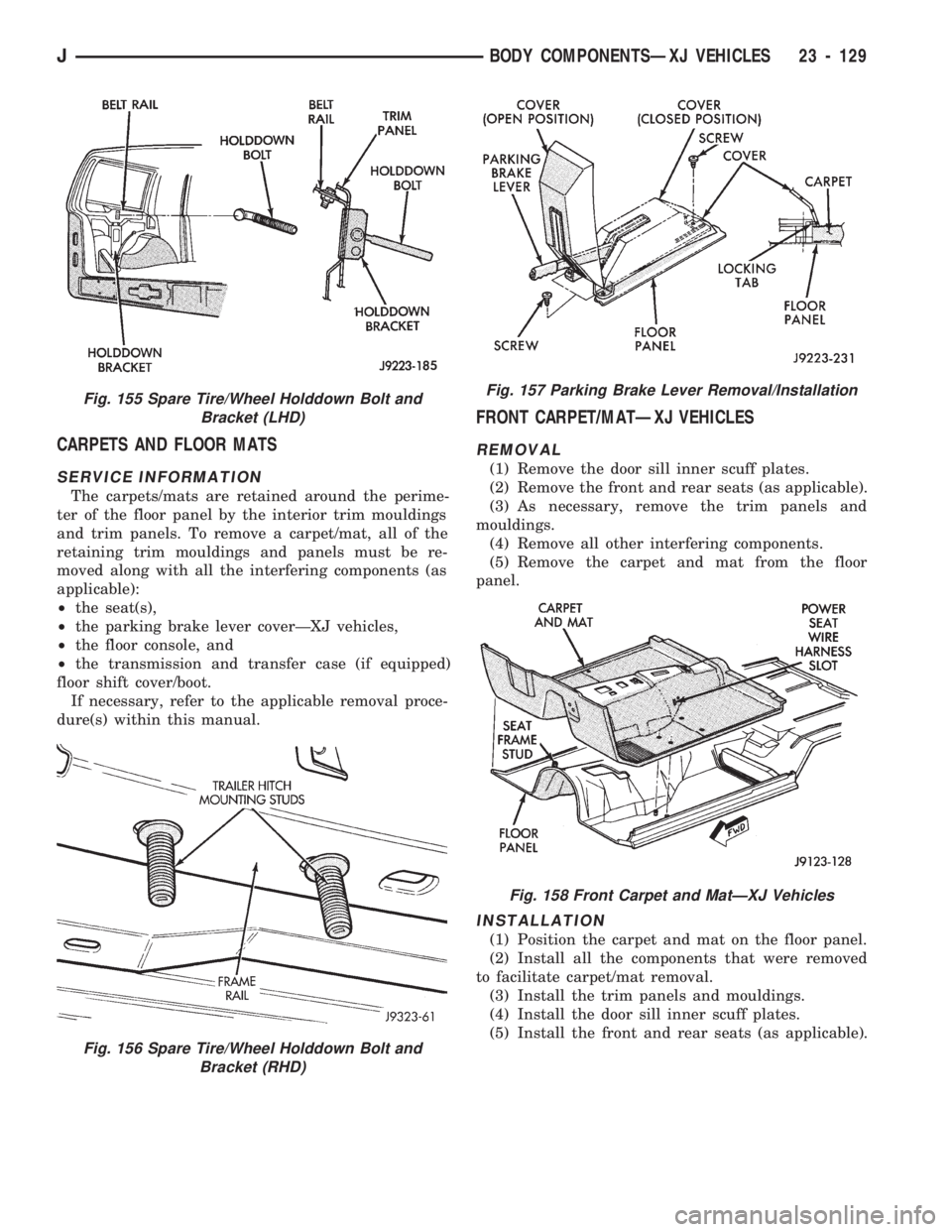
CARPETS AND FLOOR MATS
SERVICE INFORMATION
The carpets/mats are retained around the perime-
ter of the floor panel by the interior trim mouldings
and trim panels. To remove a carpet/mat, all of the
retaining trim mouldings and panels must be re-
moved along with all the interfering components (as
applicable):
²the seat(s),
²the parking brake lever coverÐXJ vehicles,
²the floor console, and
²the transmission and transfer case (if equipped)
floor shift cover/boot.
If necessary, refer to the applicable removal proce-
dure(s) within this manual.
FRONT CARPET/MATÐXJ VEHICLES
REMOVAL
(1) Remove the door sill inner scuff plates.
(2) Remove the front and rear seats (as applicable).
(3) As necessary, remove the trim panels and
mouldings.
(4) Remove all other interfering components.
(5) Remove the carpet and mat from the floor
panel.
INSTALLATION
(1) Position the carpet and mat on the floor panel.
(2) Install all the components that were removed
to facilitate carpet/mat removal.
(3) Install the trim panels and mouldings.
(4) Install the door sill inner scuff plates.
(5) Install the front and rear seats (as applicable).
Fig. 156 Spare Tire/Wheel Holddown Bolt and
Bracket (RHD)
Fig. 155 Spare Tire/Wheel Holddown Bolt and
Bracket (LHD)Fig. 157 Parking Brake Lever Removal/Installation
Fig. 158 Front Carpet and MatÐXJ Vehicles
JBODY COMPONENTSÐXJ VEHICLES 23 - 129
Page 1586 of 1784
(5) Install all the components that were removed
to facilitate carpet and mat removal.
(6) Install the trim panels and mouldings.
(7) Install the cargo tie-down footman loops on the
carpet with replacement rivets.
(8) Position the liftgate scuff plate and latch
striker on the carpet and cross sill. Install and
tighten the scuff plate screws to 1 Nzm (11 in-lbs)
torque. Tighten the latch striker screws to 30 Nzm
(22 ft-lbs) torque.
ICARGO BARRIER
REMOVAL
(1) Tilt both seats forward and raise the storage
compartment lid.
(2) Remove the wing nuts from the front side of
the cargo barrier (Fig. 164).(3) Remove the fasteners from the lower outer cor-
ners of the cargo barrier.
(4) Remove the cargo barrier.
INSTALLATION
(1) Reverse the removal procedure to install the
cargo barrier.
Fig. 164 Cargo Barrier
Fig. 163 Cargo Area MatÐXJ Vehicles
JBODY COMPONENTSÐXJ VEHICLES 23 - 131
Page 1587 of 1784
BODY COMPONENTSÐYJ VEHICLES
CONTENTS
page page
ADD-A-TRUNK........................ 198
DOORS.............................. 172
EXTERIOR COMPONENTS............... 134FIXED WINDOW GLASS................ 181
GENERAL SERVICE INFORMATION........ 132
INTERIOR COMPONENTS............... 188
GENERAL SERVICE INFORMATION
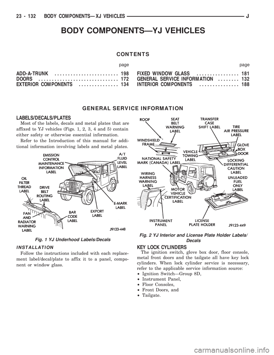
LABELS/DECALS/PLATES
Most of the labels, decals and metal plates that are
affixed to YJ vehicles (Figs. 1, 2, 3, 4 and 5) contain
either safety or otherwise essential information.
Refer to the Introduction of this manual for addi-
tional information involving labels and metal plates.
INSTALLATION
Follow the instructions included with each replace-
ment label/decal/plate to affix it to a panel, compo-
nent or window glass.
KEY LOCK CYLINDERS
The ignition switch, glove box door, floor console,
metal front doors and the tailgate all have key lock
cylinders. When lock cylinder service is necessary,
refer to the applicable service information source:
²Ignition SwitchÐGroup 8D,
²Instrument Panel,
²Floor Consoles,
²Front Doors, and
²Tailgate.
Fig. 1 YJ Underhood Labels/DecalsFig. 2 YJ Interior and License Plate Holder Labels/
Decals
23 - 132 BODY COMPONENTSÐXJ VEHICLESJ