Page 1512 of 1784
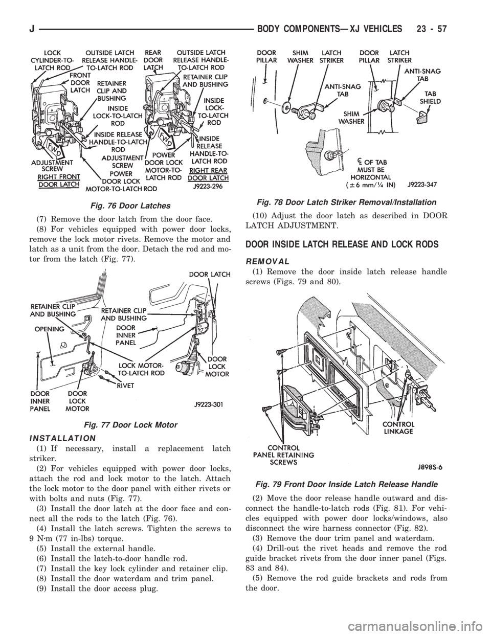
(7) Remove the door latch from the door face.
(8) For vehicles equipped with power door locks,
remove the lock motor rivets. Remove the motor and
latch as a unit from the door. Detach the rod and mo-
tor from the latch (Fig. 77).
INSTALLATION
(1) If necessary, install a replacement latch
striker.
(2) For vehicles equipped with power door locks,
attach the rod and lock motor to the latch. Attach
the lock motor to the door panel with either rivets or
with bolts and nuts (Fig. 77).
(3) Install the door latch at the door face and con-
nect all the rods to the latch (Fig. 76).
(4) Install the latch screws. Tighten the screws to
9Nzm (77 in-lbs) torque.
(5) Install the external handle.
(6) Install the latch-to-door handle rod.
(7) Install the key lock cylinder and retainer clip.
(8) Install the door waterdam and trim panel.
(9) Install the door access plug.(10) Adjust the door latch as described in DOOR
LATCH ADJUSTMENT.
DOOR INSIDE LATCH RELEASE AND LOCK RODS
REMOVAL
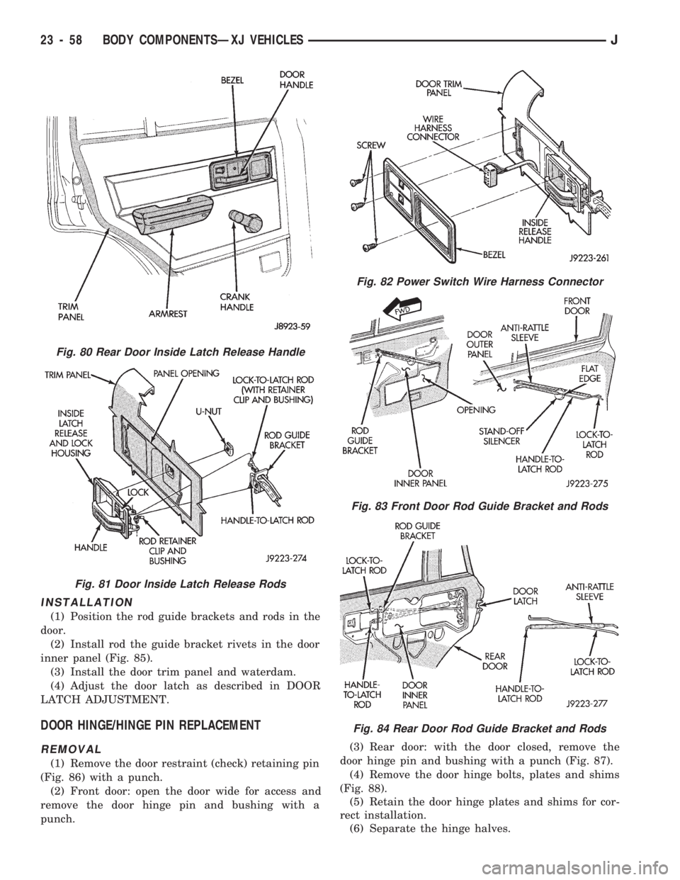
(1) Remove the door inside latch release handle
screws (Figs. 79 and 80).
(2) Move the door release handle outward and dis-
connect the handle-to-latch rods (Fig. 81). For vehi-
cles equipped with power door locks/windows, also
disconnect the wire harness connector (Fig. 82).
(3) Remove the door trim panel and waterdam.
(4) Drill-out the rivet heads and remove the rod
guide bracket rivets from the door inner panel (Figs.
83 and 84).
(5) Remove the rod guide brackets and rods from
the door.
Fig. 76 Door Latches
Fig. 77 Door Lock Motor
Fig. 78 Door Latch Striker Removal/Installation
Fig. 79 Front Door Inside Latch Release Handle
JBODY COMPONENTSÐXJ VEHICLES 23 - 57
Page 1513 of 1784
INSTALLATION
(1) Position the rod guide brackets and rods in the
door.
(2) Install rod the guide bracket rivets in the door
inner panel (Fig. 85).
(3) Install the door trim panel and waterdam.
(4) Adjust the door latch as described in DOOR
LATCH ADJUSTMENT.
DOOR HINGE/HINGE PIN REPLACEMENT
REMOVAL
(1) Remove the door restraint (check) retaining pin
(Fig. 86) with a punch.
(2) Front door: open the door wide for access and
remove the door hinge pin and bushing with a
punch.(3) Rear door: with the door closed, remove the
door hinge pin and bushing with a punch (Fig. 87).
(4) Remove the door hinge bolts, plates and shims
(Fig. 88).
(5) Retain the door hinge plates and shims for cor-
rect installation.
(6) Separate the hinge halves.
Fig. 80 Rear Door Inside Latch Release Handle
Fig. 81 Door Inside Latch Release Rods
Fig. 82 Power Switch Wire Harness Connector
Fig. 83 Front Door Rod Guide Bracket and Rods
Fig. 84 Rear Door Rod Guide Bracket and Rods
23 - 58 BODY COMPONENTSÐXJ VEHICLESJ
Page 1515 of 1784
92). Be careful not to bend the hinge when driving
the hinge pin, support may be required under the
hinge.
(8) Adjust/align latch striker and latch as neces-
sary.(9) Install the door restraint (check) retaining pin
with a punch.
FRONT DOOR SPACER BLOCKSÐTWO-DOOR
VEHICLES
REMOVAL
(1) Upper spacer block: drill-out the rivet heads
and remove them from the reinforcement plate
(Fig.93).
(2) Lower spacer block: remove the screws from the
door face Fig. 94).
(3) As applicable, remove the spacer block from the
door window frame or door face.
INSTALLATION
(1) As applicable, position the spacer block on the
door window frame or door face.
(2) Upper spacer block: Install the replacement riv-
ets in the spacer block and reinforcement plate.
Fig 89 Install Bushing In Hinge
Fig. 90 Begin To Roll Bushing Material Outward
Fig. 91 Forming A Head On The Bushing
Fig. 92 Installing The Hinge Pin
Fig. 93 Front Door Upper Spacer BlockÐTwo-Door
Vehicles
23 - 60 BODY COMPONENTSÐXJ VEHICLESJ
Page 1516 of 1784
(3) Lower spacer block: install the screws in the
door face. Tighten the screws to 1 Nzm (11 in-lbs)
torque.
DOOR EDGE GUARD/EDGE PROTECTOR STRIP
REPLACEMENT
(1) Pull outward and remove the door edge guard
strip from the door edge (Fig. 95).
(2) Position the door edge guard strip on the door
edge.
(3) Force the door edge guard strip inward until it
is seated on the door edge.
DOOR WINDOW EXTERIOR MOULDINGS
REMOVAL
(1) When removing the front or rear door window
exterior moulding, open the window completely (Figs.
96 and 97).
(2) Pry and pull the moulding sections from the
door panel flange and clips.
Fig. 95 Door Edge Guard/Protector Strip
Fig. 96 Front Door Window Exterior Moulding
Fig. 94 Front Door Lower Spacer BlockÐTwo-Door
Vehicles
JBODY COMPONENTSÐXJ VEHICLES 23 - 61
Page 1517 of 1784
INSTALLATION
(1) When installing window mouldings, start at
the forward end of the upper moulding.
(2) Force the moulding onto the door panel and con-
tinue rearward until it is completely seated on the
flange.
(3) Mate the rear moulding with the upper mould-
ing and force the moulding edge inward.
(4) Continue pressing and moving downward to
complete the installation.
(5) Position the lower moulding on the clips and
force it downward.
DOOR WINDOW GLASS AND DOOR OPENING
WEATHERSTRIP SEALS
REMOVAL
When removing the front or rear door window
glass weatherstrip seals, open the window.
The window weatherstrip seals can be removed by
hand or with the aid of a small putty knife (or sim-
ilar tool).
Fig. 97 Rear Door Window Exterior Moulding
Fig. 98 Front Door Window Glass Weatherstrip
SealsFig. 99 Rear Door Window Glass Weatherstrip Seals
23 - 62 BODY COMPONENTSÐXJ VEHICLESJ
Page 1518 of 1784
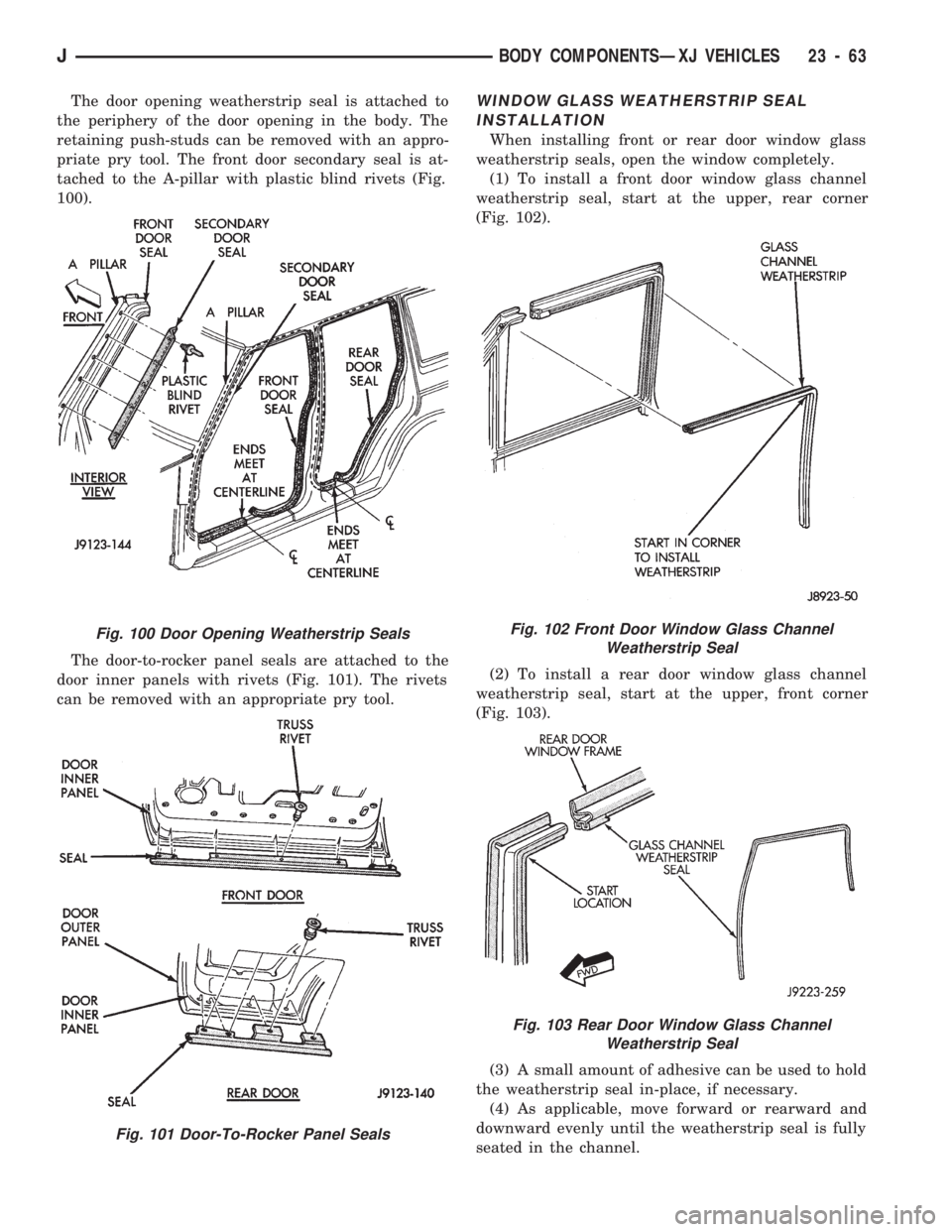
The door opening weatherstrip seal is attached to
the periphery of the door opening in the body. The
retaining push-studs can be removed with an appro-
priate pry tool. The front door secondary seal is at-
tached to the A-pillar with plastic blind rivets (Fig.
100).
The door-to-rocker panel seals are attached to the
door inner panels with rivets (Fig. 101). The rivets
can be removed with an appropriate pry tool.WINDOW GLASS WEATHERSTRIP SEAL
INSTALLATION
When installing front or rear door window glass
weatherstrip seals, open the window completely.
(1) To install a front door window glass channel
weatherstrip seal, start at the upper, rear corner
(Fig. 102).
(2) To install a rear door window glass channel
weatherstrip seal, start at the upper, front corner
(Fig. 103).
(3) A small amount of adhesive can be used to hold
the weatherstrip seal in-place, if necessary.
(4) As applicable, move forward or rearward and
downward evenly until the weatherstrip seal is fully
seated in the channel.
Fig. 100 Door Opening Weatherstrip Seals
Fig. 101 Door-To-Rocker Panel Seals
Fig. 102 Front Door Window Glass Channel
Weatherstrip Seal
Fig. 103 Rear Door Window Glass Channel
Weatherstrip Seal
JBODY COMPONENTSÐXJ VEHICLES 23 - 63
Page 1519 of 1784
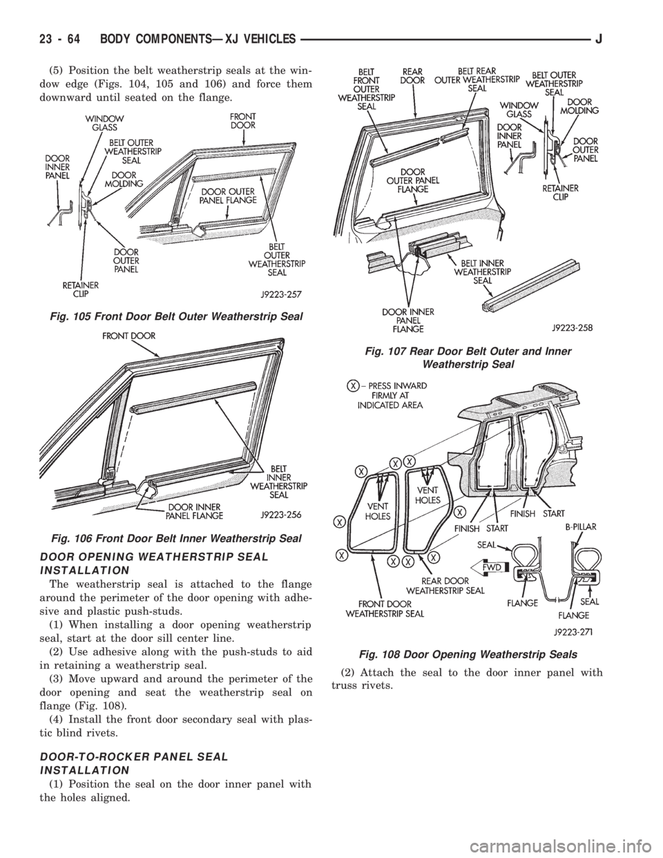
(5) Position the belt weatherstrip seals at the win-
dow edge (Figs. 104, 105 and 106) and force them
downward until seated on the flange.
DOOR OPENING WEATHERSTRIP SEAL
INSTALLATION
The weatherstrip seal is attached to the flange
around the perimeter of the door opening with adhe-
sive and plastic push-studs.
(1) When installing a door opening weatherstrip
seal, start at the door sill center line.
(2) Use adhesive along with the push-studs to aid
in retaining a weatherstrip seal.
(3) Move upward and around the perimeter of the
door opening and seat the weatherstrip seal on
flange (Fig. 108).
(4) Install the front door secondary seal with plas-
tic blind rivets.
DOOR-TO-ROCKER PANEL SEAL
INSTALLATION
(1) Position the seal on the door inner panel with
the holes aligned.(2) Attach the seal to the door inner panel with
truss rivets.
Fig. 105 Front Door Belt Outer Weatherstrip Seal
Fig. 106 Front Door Belt Inner Weatherstrip Seal
Fig. 107 Rear Door Belt Outer and Inner
Weatherstrip Seal
Fig. 108 Door Opening Weatherstrip Seals
23 - 64 BODY COMPONENTSÐXJ VEHICLESJ
Page 1539 of 1784
UNDERBODY COMPONENTS
INDEX
page page
Catalytic Converter/Muffler/Tailpipe Support
Brackets............................. 85
Front Skid Plate......................... 84
Fuel and Brake Fluid Tube Retainer Clip....... 86
Fuel Filler Hose Splash ShieldÐXJ Vehicles.... 86
Fuel Filter Bracket........................ 86Fuel Tank Skid Plate...................... 84
Fuel Tank Support Strap................... 86
Rear Tow HookÐXJ Vehicles............... 87
Service Information....................... 84
Trailer Hitches........................... 88
Transfer Case Skid Plate.................. 84
SERVICE INFORMATION
In some cases, components in the following proce-
dures either support, or are concealed by other com-
ponents. When necessary, refer to component
removal procedure for service access.
FRONT SKID PLATE
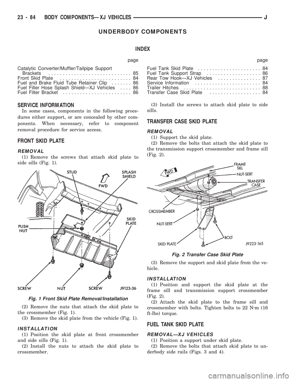
REMOVAL
(1) Remove the screws that attach skid plate to
side sills (Fig. 1).
(2) Remove the nuts that attach the skid plate to
the crossmember (Fig. 1).
(3) Remove the skid plate from the vehicle (Fig. 1).
INSTALLATION
(1) Position the skid plate at front crossmember
and side sills (Fig. 1).
(2) Install the nuts to attach the skid plate to
crossmember.(3) Install the screws to attach skid plate to side
sills.
TRANSFER CASE SKID PLATE
REMOVAL
(1) Support the skid plate.
(2) Remove the bolts that attach the skid plate to
the transmission support crossmember and frame sill
(Fig. 2).
(3) Remove the support and skid plate from the ve-
hicle.
INSTALLATION
(1) Position and support the skid plate at the
frame sill and transmission support crossmember
(Fig. 2).
(2) Attach the skid plate to the frame sill and
crossmember with bolts. Tighten bolts to 22 Nzm (16
ft-lbs) torque.
FUEL TANK SKID PLATE
REMOVALÐXJ VEHICLES
(1) Position a support under skid plate.
(2) Remove the bolts that attach skid plate to un-
derbody side rails (Figs. 3 and 4).
Fig. 1 Front Skid Plate Removal/Installation
Fig. 2 Transfer Case Skid Plate
23 - 84 BODY COMPONENTSÐXJ VEHICLESJ