1994 JEEP CHEROKEE front
[x] Cancel search: frontPage 1426 of 1784
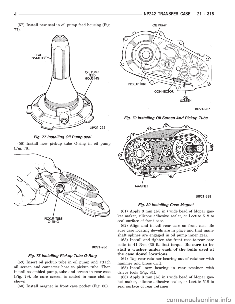
(57) Install new seal in oil pump feed housing (Fig.
77).
(58) Install new pickup tube O-ring in oil pump
(Fig. 78).
(59) Insert oil pickup tube in oil pump and attach
oil screen and connecter hose to pickup tube. Then
install assembled pump, tube and screen in rear case
(Fig. 79). Be sure screen is seated in case slot as
shown.
(60) Install magnet in front case pocket (Fig. 80).(61) Apply 3 mm (1/8 in.) wide bead of Mopar gas-
ket maker, silicone adhesive sealer, or Loctite 518 to
seal surface of front case.
(62) Align and install rear case on front case. Be
sure case locating dowels are in place and that main-
shaft splines are engaged in oil pump inner gear.
(63) Install and tighten the front case-to-rear case
bolts to 41 Nzm (30 ft. lbs.) torque.Be sure to in-
stall a washer under each of the bolts used at
the case dowel locations.
(64) Tap rear retainer bearing out of retainer with
hammer and brass drift.
(65) Install new bearing in rear retainer with
driver tools (Fig. 81).
(66) Apply 3 mm (1/8 in.) wide bead of Mopar gas-
ket maker, silicone adhesive sealer, or Loctite 518 to
seal surface of rear retainer.
Fig. 77 Installing Oil Pump seal
Fig. 78 Installing Pickup Tube O-Ring
Fig. 79 Installing Oil Screen And Pickup Tube
Fig. 80 Installing Case Magnet
JNP242 TRANSFER CASE 21 - 315
Page 1428 of 1784
(72) Apply 3 mm (1/8 in.) wide bead of Mopar gas-
ket maker, silicone adhesive sealer, or Loctite 518 to
seal surface of extension housing.
(73) Install extension housing on case. Tighten
housing bolts to 41 Nzm (30 ft. lbs.) torque.
(74) Install front yoke. Secure yoke with new seal
washer and nut. Tighten nut to 149 Nzm (110 ft. lbs.)
torque.
(75) Install new gasket on vacuum switch and in-
stall switch in the case. Tighten switch to 27 Nzm (20
ft. lbs.) torque.
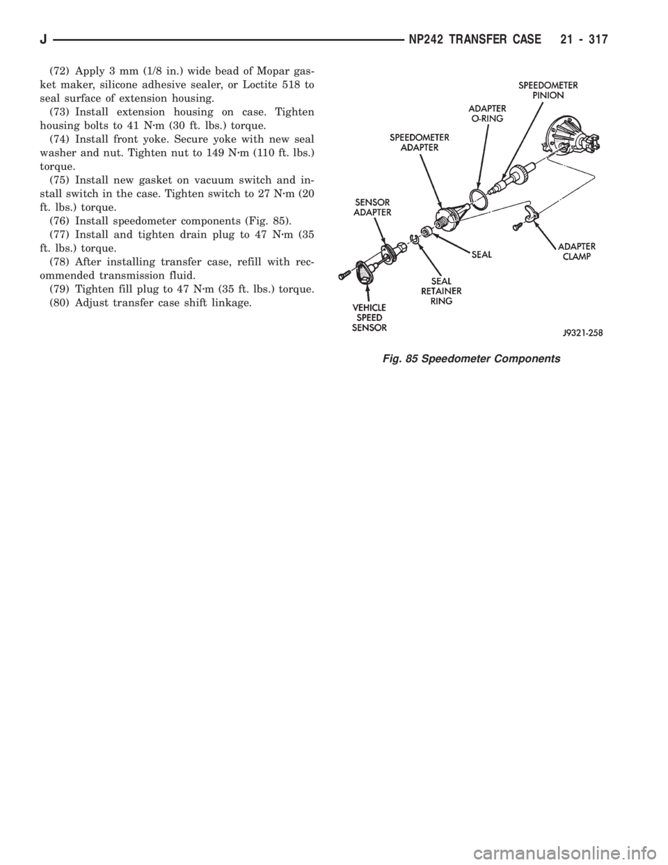
(76) Install speedometer components (Fig. 85).
(77) Install and tighten drain plug to 47 Nzm (35
ft. lbs.) torque.
(78) After installing transfer case, refill with rec-
ommended transmission fluid.
(79) Tighten fill plug to 47 Nzm (35 ft. lbs.) torque.
(80) Adjust transfer case shift linkage.
Fig. 85 Speedometer Components
JNP242 TRANSFER CASE 21 - 317
Page 1444 of 1784
WHEELS AND TIRES
CONTENTS
page page
SPECIFICATIONS....................... 11
TIRES................................. 1VEHICLE VIBRATION..................... 9
WHEELS............................... 6
TIRES
INDEX
page page
Cleaning of Tires.......................... 2
General Information........................ 1
Pressure Gauges......................... 2
Repairing Leaks.......................... 3
Replacement Tires........................ 2Rotation................................ 3
Tire Inflation Pressures..................... 2
Tire Noise or Vibration..................... 4
Tire Wear Patterns........................ 4
Tread Wear Indicators...................... 3
GENERAL INFORMATION
Tires are designed for each specific vehicle. They
provide the best overall performance for normal op-
eration. The ride and handling characteristics match
the vehicle's requirements. With proper care they
will give excellent reliability, traction, skid resis-
tance, and tread life. These tires have specific load
carrying capacities. When correctly inflated, they
will operate properly.
Tires used in cool climates, and with light loads
will have a longer life than tires used in hot climates
with heavy loads. Abrasive road surfaces will accel-
erate tire wear.
Driving habits have more effect on tire life than
any other factor. Careful drivers will obtain much
greater mileage than careless drivers.
Driving habits that shorten the life of any tire;
²Rapid acceleration and deceleration
²Severe application of brakes
²High-speed driving
²Taking turns at excessive speeds
²Striking curbs and other obstacles
It is very important to follow the tire rotation in-
terval
IDENTIFICATION
Tire type, size, aspect ratio and speed rating are
encoded in the letters and numbers imprinted on the
side wall of the tire. Refer to the chart to decipher
the tire identification code (Fig. 1).
Performance tires will have a speed rating letter
after the aspect ratio number. The speed rating isnot always printed on the tire sidewall. The letterS
indicates that the tire is speed rated up to 112 mph.
²Qup to 100 mph
²Tup to 118 mph
²Uup to 124 mph
²Hup to 130 mph
²Vup to 149 mph
²Zmore than 149 mph (consult the tire manufac-
turer for the specific speed rating)
An All Season type tire will have eitherM+S,M
&SorMÐS(indicating mud and snow traction) im-
printed on the side wall.
RADIAL-PLY TIRES
Radial-ply tires improve handling, tread life, ride
quality and decrease rolling resistance.
Radial-ply tires must always be used in sets of
four. Under no circumstances should they be used on
the front only. They may be mixed with temporary
spare tires when necessary, but reduced speeds are
recommended.
Radial-ply tires have the same load-carrying capac-
ity as other types of tires of the same size. They use
the same recommended inflation pressures.
SPARE TIRE (TEMPORARY)
The compact spare tire is designed for emergency
use only. The original tire should be repaired and re-
installed at the first opportunity. Refer to Owner's
Manual for complete details.
JWHEELS AND TIRES 22 - 1
Page 1446 of 1784
²Noise
²Handling
²Durability
²Tread life
²Traction
²Rolling resistance
²Speed capability
Original equipment tires should be used when re-
placement is needed.
Refer to the placard on the vehicle or the
Owner's Manual for the correct replacement
tire.
Failure to use original or equivalent replacement
tires may adversely affect the handling of the vehi-
cle.
The use of oversize tiresis not recommended.
They may cause interference with vehicle suspension
and steering travel. This can cause tire damage or
failure.
WARNING: FAILURE TO EQUIP THE VEHICLE WITH
TIRES HAVING ADEQUATE LOAD CAPABILITY CAN
RESULT IN SUDDEN TIRE FAILURE.
ROTATION
Tires on the front and rear axles operate at differ-
ent loads and perform different steering, driving, and
braking functions. For these reasons, the tires wear
at unequal rates. They may also develop irregular
wear patterns. These effects can be reduced by rotat-
ing the tires according to the maintenance schedule
in the Owners Manual. This will improve tread life,
traction and maintain a smooth quiet ride.
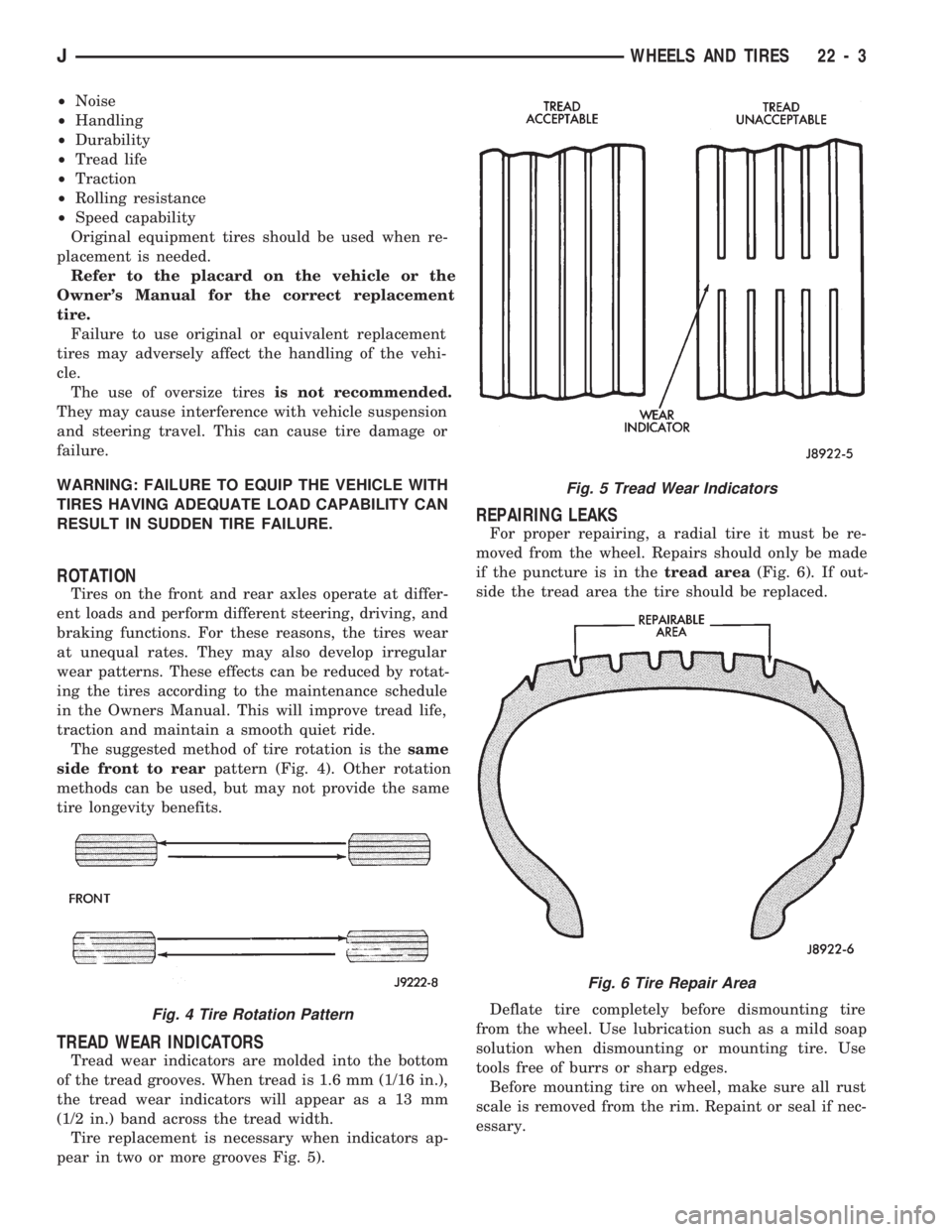
The suggested method of tire rotation is thesame
side front to rearpattern (Fig. 4). Other rotation
methods can be used, but may not provide the same
tire longevity benefits.
TREAD WEAR INDICATORS
Tread wear indicators are molded into the bottom
of the tread grooves. When tread is 1.6 mm (1/16 in.),
the tread wear indicators will appear as a 13 mm
(1/2 in.) band across the tread width.
Tire replacement is necessary when indicators ap-
pear in two or more grooves Fig. 5).
REPAIRING LEAKS
For proper repairing, a radial tire it must be re-
moved from the wheel. Repairs should only be made
if the puncture is in thetread area(Fig. 6). If out-
side the tread area the tire should be replaced.
Deflate tire completely before dismounting tire
from the wheel. Use lubrication such as a mild soap
solution when dismounting or mounting tire. Use
tools free of burrs or sharp edges.
Before mounting tire on wheel, make sure all rust
scale is removed from the rim. Repaint or seal if nec-
essary.
Fig. 4 Tire Rotation Pattern
Fig. 5 Tread Wear Indicators
Fig. 6 Tire Repair Area
JWHEELS AND TIRES 22 - 3
Page 1453 of 1784
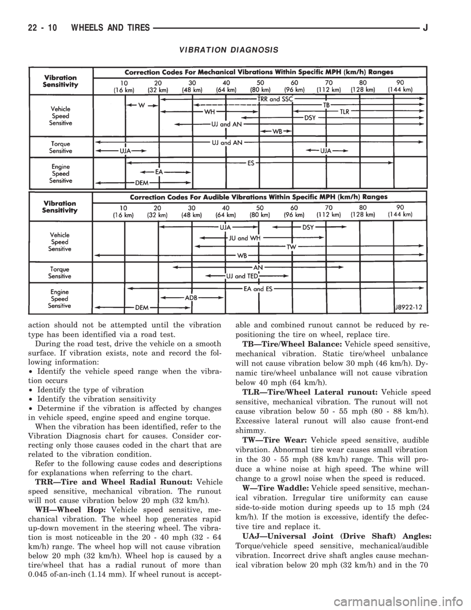
action should not be attempted until the vibration
type has been identified via a road test.
During the road test, drive the vehicle on a smooth
surface. If vibration exists, note and record the fol-
lowing information:
²Identify the vehicle speed range when the vibra-
tion occurs
²Identify the type of vibration
²Identify the vibration sensitivity
²Determine if the vibration is affected by changes
in vehicle speed, engine speed and engine torque.
When the vibration has been identified, refer to the
Vibration Diagnosis chart for causes. Consider cor-
recting only those causes coded in the chart that are
related to the vibration condition.
Refer to the following cause codes and descriptions
for explanations when referring to the chart.
TRRÐTire and Wheel Radial Runout:Vehicle
speed sensitive, mechanical vibration. The runout
will not cause vibration below 20 mph (32 km/h).
WHÐWheel Hop:Vehicle speed sensitive, me-
chanical vibration. The wheel hop generates rapid
up-down movement in the steering wheel. The vibra-
tion is most noticeable in the 20 - 40 mph (32 - 64
km/h) range. The wheel hop will not cause vibration
below 20 mph (32 km/h). Wheel hop is caused by a
tire/wheel that has a radial runout of more than
0.045 of-an-inch (1.14 mm). If wheel runout is accept-able and combined runout cannot be reduced by re-
positioning the tire on wheel, replace tire.
TBÐTire/Wheel Balance:Vehicle speed sensitive,
mechanical vibration. Static tire/wheel unbalance
will not cause vibration below 30 mph (46 km/h). Dy-
namic tire/wheel unbalance will not cause vibration
below 40 mph (64 km/h).
TLRÐTire/Wheel Lateral runout:Vehicle speed
sensitive, mechanical vibration. The runout will not
cause vibration below 50 - 55 mph (80 - 88 km/h).
Excessive lateral runout will also cause front-end
shimmy.
TWÐTire Wear:Vehicle speed sensitive, audible
vibration. Abnormal tire wear causes small vibration
in the 30 - 55 mph (88 km/h) range. This will pro-
duce a whine noise at high speed. The whine will
change to a growl noise when the speed is reduced.
WÐTire Waddle:Vehicle speed sensitive, mechan-
ical vibration. Irregular tire uniformity can cause
side-to-side motion during speeds up to 15 mph (24
km/h). If the motion is excessive, identify the defec-
tive tire and replace it.
UAJÐUniversal Joint (Drive Shaft) Angles:
Torque/vehicle speed sensitive, mechanical/audible
vibration. Incorrect drive shaft angles cause mechan-
ical vibration below 20 mph (32 km/h) and in the 70
VIBRATION DIAGNOSIS
22 - 10 WHEELS AND TIRESJ
Page 1457 of 1784
KEY LOCK CYLINDERS
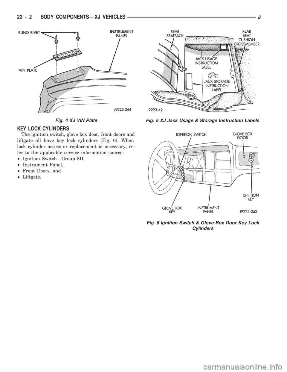
The ignition switch, glove box door, front doors and
liftgate all have key lock cylinders (Fig. 6). When
lock cylinder access or replacement is necessary, re-
fer to the applicable service information source:
²Ignition SwitchÐGroup 8D,
²Instrument Panel,
²Front Doors, and
²Liftgate.
Fig. 4 XJ VIN PlateFig. 5 XJ Jack Usage & Storage Instruction Labels
Fig. 6 Ignition Switch & Glove Box Door Key Lock
Cylinders
23 - 2 BODY COMPONENTSÐXJ VEHICLESJ
Page 1458 of 1784
EXTERIOR COMPONENTS
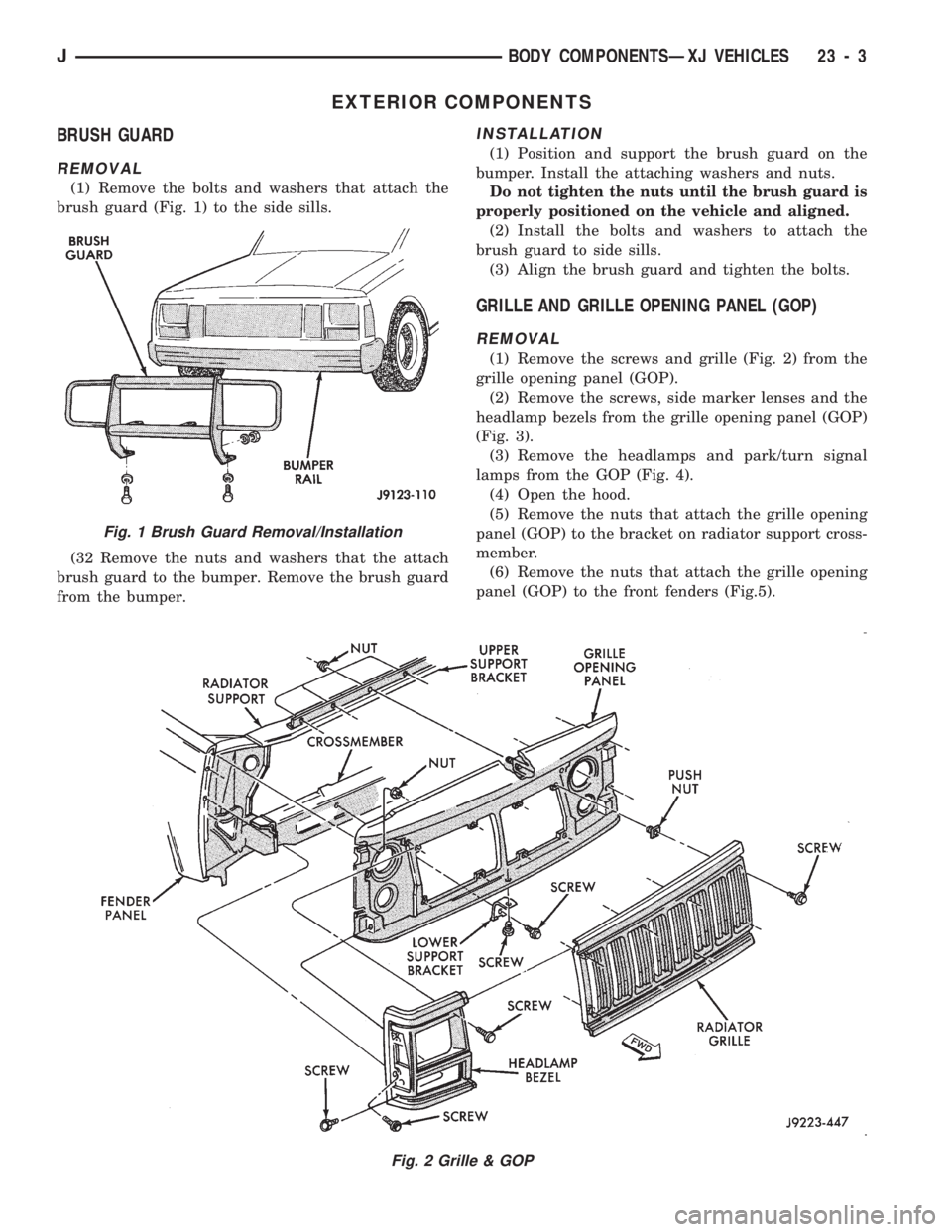
BRUSH GUARD
REMOVAL
(1) Remove the bolts and washers that attach the
brush guard (Fig. 1) to the side sills.
(32 Remove the nuts and washers that the attach
brush guard to the bumper. Remove the brush guard
from the bumper.
INSTALLATION
(1) Position and support the brush guard on the
bumper. Install the attaching washers and nuts.
Do not tighten the nuts until the brush guard is
properly positioned on the vehicle and aligned.
(2) Install the bolts and washers to attach the
brush guard to side sills.
(3) Align the brush guard and tighten the bolts.
GRILLE AND GRILLE OPENING PANEL (GOP)
REMOVAL
(1) Remove the screws and grille (Fig. 2) from the
grille opening panel (GOP).
(2) Remove the screws, side marker lenses and the
headlamp bezels from the grille opening panel (GOP)
(Fig. 3).
(3) Remove the headlamps and park/turn signal
lamps from the GOP (Fig. 4).
(4) Open the hood.
(5) Remove the nuts that attach the grille opening
panel (GOP) to the bracket on radiator support cross-
member.
(6) Remove the nuts that attach the grille opening
panel (GOP) to the front fenders (Fig.5).
Fig. 2 Grille & GOP
Fig. 1 Brush Guard Removal/Installation
JBODY COMPONENTSÐXJ VEHICLES 23 - 3
Page 1459 of 1784
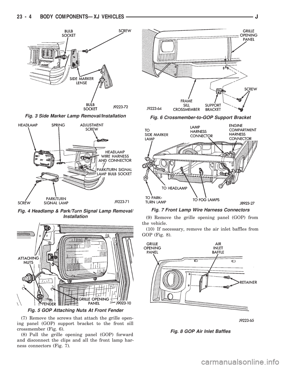
(7) Remove the screws that attach the grille open-
ing panel (GOP) support bracket to the front sill
crossmember (Fig. 6).
(8) Pull the grille opening panel (GOP) forward
and disconnect the clips and all the front lamp har-
ness connectors (Fig. 7).(9) Remove the grille opening panel (GOP) from
the vehicle.
(10) If necessary, remove the air inlet baffles from
GOP (Fig. 8).
Fig. 3 Side Marker Lamp Removal/Installation
Fig. 4 Headlamp & Park/Turn Signal Lamp Removal/
Installation
Fig. 5 GOP Attaching Nuts At Front Fender
Fig. 6 Crossmember-to-GOP Support Bracket
Fig. 7 Front Lamp Wire Harness Connectors
Fig. 8 GOP Air Inlet Baffles
23 - 4 BODY COMPONENTSÐXJ VEHICLESJ