Page 1371 of 1784
²Race outer diameter is 48.9 mm (1.925 in.) and in-
side diameter is 26.0 mm (1.024 in.).
²Bearing outer diameter is 46.7 mm (1.839 in.) and
inside diameter is 26.0 mm (1.024 in.).
(31) Coat front planetary ring gear race with pe-
troleum jelly and install it in ring gear (Fig. 25).
(32) Verify ring gear race size. Outer diameter is
47.0 mm (1.850 in.) and inside diameter is 26.5 mm
(1.045 in.).
(33) Align forward-direct clutch disc splines with
screwdriver (Fig. 26).
(34) Align and install front planetary ring gear in
forward-direct clutch (Fig. 27).
Fig. 24 Installing Forward-Direct Clutch Thrust Bearing
And Race
Fig. 21 Installing Planetary Thrust Race
Fig. 22 Installing Second Coast Brake Band
Fig. 23 Installing Second Coast Brake Band Retaining Pin
21 - 260 AW-4 TRANSMISSION OVERHAULJ
Page 1372 of 1784
(35) Coat bearing and race with petroleum jelly
and install them in ring gear (Fig. 28). Verify bear-
ing/race size.
²Bearing outer diameter is 47.7 mm (1.878 in.) and
inside diameter is 32.6 mm (1.283 in.).
²Race outer diameter is 53.6 mm (2.110 in.) and in-
side diameter is 30.6 mm (1.205 in.).
(36) Rotate front of transmission case downward
and install assembled planetary gear/forward-direct
clutch (Fig. 29).
Fig. 25 Installing Planetary Ring Gear Race
Fig. 26 Aligning Forward-Direct Clutch Splines
Fig. 27 Installing Front Planetary Ring Gear
Fig. 28 Installing Ring Gear Bearing And Race
ART: j8921-696; SIZE (3) = 3-1/2h x 3-1/2w
Fig. 29 Installing Front Planetary And Forward-
Direct Clutch Assembly
JAW-4 TRANSMISSION OVERHAUL 21 - 261
Page 1373 of 1784
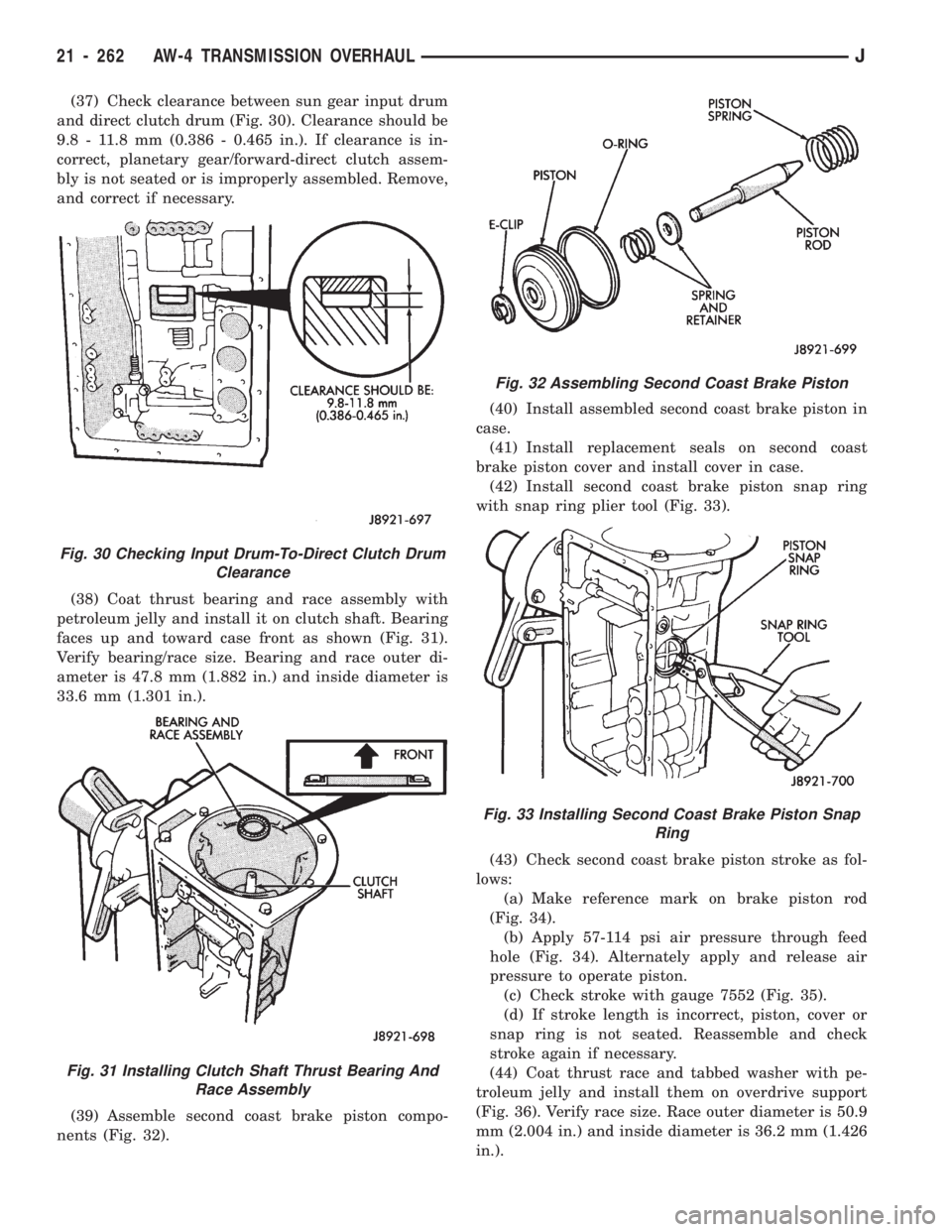
(37) Check clearance between sun gear input drum
and direct clutch drum (Fig. 30). Clearance should be
9.8 - 11.8 mm (0.386 - 0.465 in.). If clearance is in-
correct, planetary gear/forward-direct clutch assem-
bly is not seated or is improperly assembled. Remove,
and correct if necessary.
(38) Coat thrust bearing and race assembly with
petroleum jelly and install it on clutch shaft. Bearing
faces up and toward case front as shown (Fig. 31).
Verify bearing/race size. Bearing and race outer di-
ameter is 47.8 mm (1.882 in.) and inside diameter is
33.6 mm (1.301 in.).
(39) Assemble second coast brake piston compo-
nents (Fig. 32).(40) Install assembled second coast brake piston in
case.
(41) Install replacement seals on second coast
brake piston cover and install cover in case.
(42) Install second coast brake piston snap ring
with snap ring plier tool (Fig. 33).
(43) Check second coast brake piston stroke as fol-
lows:
(a) Make reference mark on brake piston rod
(Fig. 34).
(b) Apply 57-114 psi air pressure through feed
hole (Fig. 34). Alternately apply and release air
pressure to operate piston.
(c) Check stroke with gauge 7552 (Fig. 35).
(d) If stroke length is incorrect, piston, cover or
snap ring is not seated. Reassemble and check
stroke again if necessary.
(44) Coat thrust race and tabbed washer with pe-
troleum jelly and install them on overdrive support
(Fig. 36). Verify race size. Race outer diameter is 50.9
mm (2.004 in.) and inside diameter is 36.2 mm (1.426
in.).
Fig. 30 Checking Input Drum-To-Direct Clutch Drum
Clearance
Fig. 31 Installing Clutch Shaft Thrust Bearing And
Race Assembly
Fig. 32 Assembling Second Coast Brake Piston
Fig. 33 Installing Second Coast Brake Piston Snap
Ring
21 - 262 AW-4 TRANSMISSION OVERHAULJ
Page 1374 of 1784
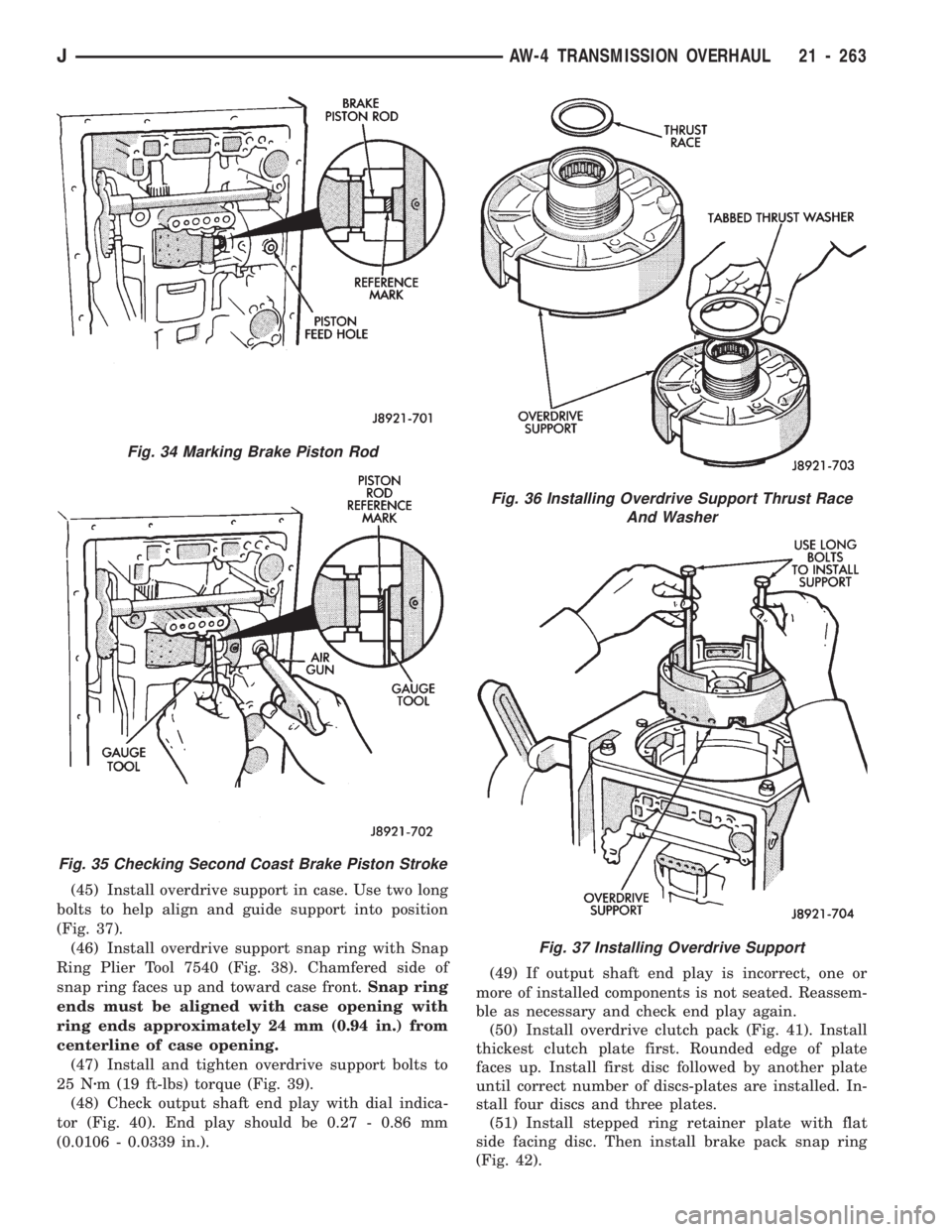
(45) Install overdrive support in case. Use two long
bolts to help align and guide support into position
(Fig. 37).
(46) Install overdrive support snap ring with Snap
Ring Plier Tool 7540 (Fig. 38). Chamfered side of
snap ring faces up and toward case front.Snap ring
ends must be aligned with case opening with
ring ends approximately 24 mm (0.94 in.) from
centerline of case opening.
(47) Install and tighten overdrive support bolts to
25 Nzm (19 ft-lbs) torque (Fig. 39).
(48) Check output shaft end play with dial indica-
tor (Fig. 40). End play should be 0.27 - 0.86 mm
(0.0106 - 0.0339 in.).(49) If output shaft end play is incorrect, one or
more of installed components is not seated. Reassem-
ble as necessary and check end play again.
(50) Install overdrive clutch pack (Fig. 41). Install
thickest clutch plate first. Rounded edge of plate
faces up. Install first disc followed by another plate
until correct number of discs-plates are installed. In-
stall four discs and three plates.
(51) Install stepped ring retainer plate with flat
side facing disc. Then install brake pack snap ring
(Fig. 42).
Fig. 36 Installing Overdrive Support Thrust Race
And Washer
Fig. 37 Installing Overdrive Support
Fig. 34 Marking Brake Piston Rod
Fig. 35 Checking Second Coast Brake Piston Stroke
JAW-4 TRANSMISSION OVERHAUL 21 - 263
Page 1384 of 1784
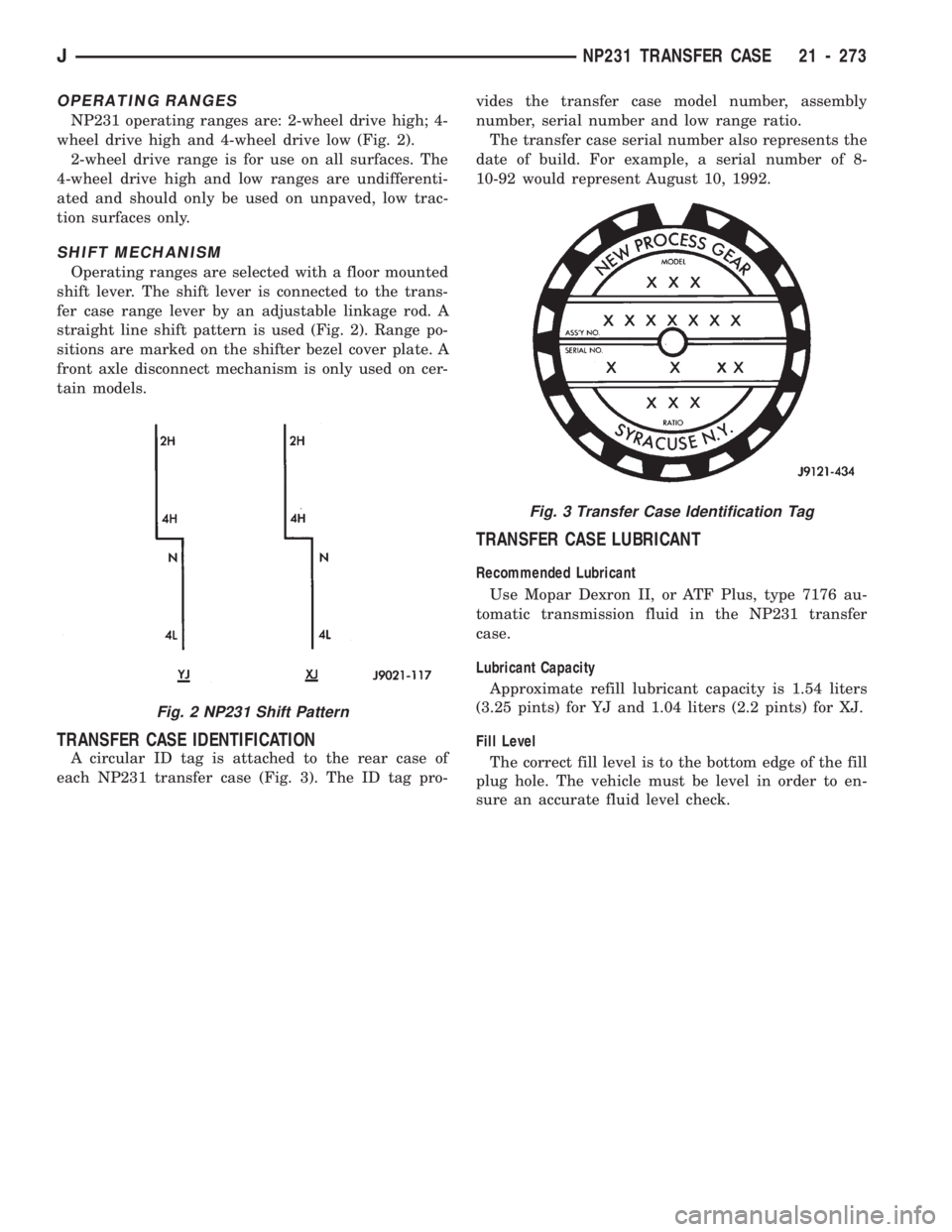
OPERATING RANGES
NP231 operating ranges are: 2-wheel drive high; 4-
wheel drive high and 4-wheel drive low (Fig. 2).
2-wheel drive range is for use on all surfaces. The
4-wheel drive high and low ranges are undifferenti-
ated and should only be used on unpaved, low trac-
tion surfaces only.
SHIFT MECHANISM
Operating ranges are selected with a floor mounted
shift lever. The shift lever is connected to the trans-
fer case range lever by an adjustable linkage rod. A
straight line shift pattern is used (Fig. 2). Range po-
sitions are marked on the shifter bezel cover plate. A
front axle disconnect mechanism is only used on cer-
tain models.
TRANSFER CASE IDENTIFICATION
A circular ID tag is attached to the rear case of
each NP231 transfer case (Fig. 3). The ID tag pro-vides the transfer case model number, assembly
number, serial number and low range ratio.
The transfer case serial number also represents the
date of build. For example, a serial number of 8-
10-92 would represent August 10, 1992.
TRANSFER CASE LUBRICANT
Recommended Lubricant
Use Mopar Dexron II, or ATF Plus, type 7176 au-
tomatic transmission fluid in the NP231 transfer
case.
Lubricant Capacity
Approximate refill lubricant capacity is 1.54 liters
(3.25 pints) for YJ and 1.04 liters (2.2 pints) for XJ.
Fill Level
The correct fill level is to the bottom edge of the fill
plug hole. The vehicle must be level in order to en-
sure an accurate fluid level check.
Fig. 2 NP231 Shift Pattern
Fig. 3 Transfer Case Identification Tag
JNP231 TRANSFER CASE 21 - 273
Page 1387 of 1784
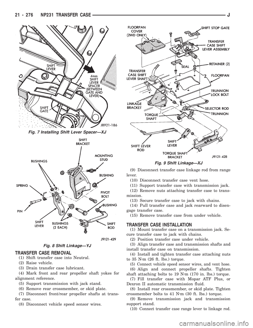
TRANSFER CASE REMOVAL
(1) Shift transfer case into Neutral.
(2) Raise vehicle.
(3) Drain transfer case lubricant.
(4) Mark front and rear propeller shaft yokes for
alignment reference.
(5) Support transmission with jack stand.
(6) Remove rear crossmember, or skid plate.
(7) Disconnect front/rear propeller shafts at trans-
fer case.
(8) Disconnect vehicle speed sensor wires.(9) Disconnect transfer case linkage rod from range
lever.
(10) Disconnect transfer case vent hose.
(11) Support transfer case with transmission jack.
(12) Remove nuts attaching transfer case to trans-
mission.
(13) Secure transfer case to jack with chains.
(14) Pull transfer case and jack rearward to disen-
gage transfer case.
(15) Remove transfer case from under vehicle.
TRANSFER CASE INSTALLATION
(1) Mount transfer case on a transmission jack. Se-
cure transfer case to jack with chains.
(2) Position transfer case under vehicle.
(3) Align transfer case and transmission shafts and
install transfer case on transmission.
(4) Install and tighten transfer case attaching nuts
to 35 Nzm (26 ft. lbs.) torque.
(5) Connect vehicle speed sensor wires, and vent hose.
(6) Align and connect propeller shafts. Tighten
shaft attaching bolts to 19 Nzm (170 in. lbs.) torque.
(7) Fill transfer case with Mopar ATF Plus, or
Dexron II automatic transmission fluid.
(8) Install rear crossmember, or skid plate. Tighten
crossmember bolts to 41 Nzm (30 ft. lbs.) torque.
(9) Remove transmission jack and transmission
support stand.
(10) Connect transfer case range lever to linkage rod.
Fig. 7 Installing Shift Lever SpacerÐXJ
Fig. 8 Shift LinkageÐYJ
Fig. 9 Shift LinkageÐXJ
21 - 276 NP231 TRANSFER CASEJ
Page 1388 of 1784
(11) Adjust transfer case shift linkage.
(12) Lower vehicle.
TRANSFER CASE DISASSEMBLY AND OVERHAUL
Two versions of the NP231 are used in current
models. One version retains the synchronizer
components used in previous years. A newly intro-
duced version does not have synchro components.
The non-synchro version does not have a synchro
gear, struts, spring and stop ring. During over-
haul, note which version is being serviced and or-
der needed parts accordingly.
(1) Remove fill and drain plugs.
(2) Remove front yoke. Discard yoke seal washer
and nut. They should not be reused.
(3) Move transfer case range lever rearward to 4L
position.
(4) Remove extension housing attaching bolts.
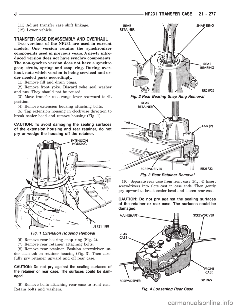
(5) Tap extension housing in clockwise direction to
break sealer bead and remove housing (Fig. 1).
CAUTION: To avoid damaging the sealing surfaces
of the extension housing and rear retainer, do not
pry or wedge the housing off the retainer.
(6) Remove rear bearing snap ring (Fig. 2).
(7) Remove rear retainer attaching bolts.
(8) Remove rear retainer. Position screwdriver un-
der each tab on retainer housing (Fig. 3). Then care-
fully pry retainer upward and off rear case.
CAUTION: Do not pry against the sealing surfaces of
the retainer or rear case. The surfaces could be dam-
aged.
(9) Remove bolts attaching rear case to front case.
Retain bolts and washers.
(10) Separate rear case from front case (Fig. 4) Insert
screwdrivers into slots cast in case ends. Then gently
pry upward to break sealer bead and loosen rear case.
CAUTION: Do not pry against the sealing surfaces
of the retainer or rear case. The surfaces could be
damaged.
Fig. 1 Extension Housing Removal
Fig. 2 Rear Bearing Snap Ring Removal
Fig. 3 Rear Retainer Removal
Fig. 4 Loosening Rear Case
JNP231 TRANSFER CASE 21 - 277
Page 1389 of 1784
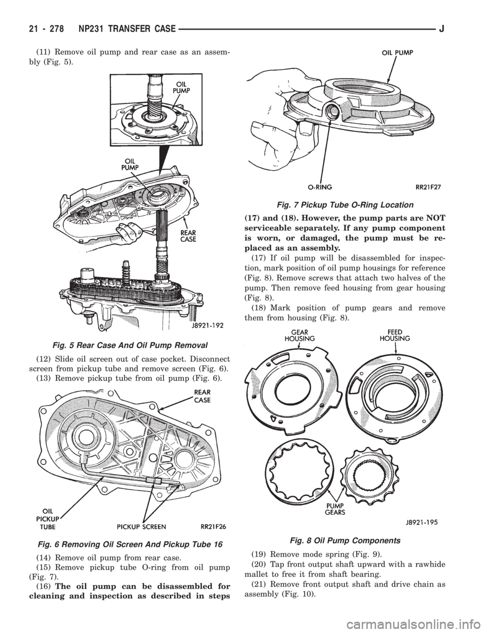
(11) Remove oil pump and rear case as an assem-
bly (Fig. 5).
(12) Slide oil screen out of case pocket. Disconnect
screen from pickup tube and remove screen (Fig. 6).
(13) Remove pickup tube from oil pump (Fig. 6).
(14) Remove oil pump from rear case.
(15) Remove pickup tube O-ring from oil pump
(Fig. 7).
(16)The oil pump can be disassembled for
cleaning and inspection as described in steps(17) and (18). However, the pump parts are NOT
serviceable separately. If any pump component
is worn, or damaged, the pump must be re-
placed as an assembly.
(17) If oil pump will be disassembled for inspec-
tion, mark position of oil pump housings for reference
(Fig. 8). Remove screws that attach two halves of the
pump. Then remove feed housing from gear housing
(Fig. 8).
(18) Mark position of pump gears and remove
them from housing (Fig. 8).
(19) Remove mode spring (Fig. 9).
(20) Tap front output shaft upward with a rawhide
mallet to free it from shaft bearing.
(21) Remove front output shaft and drive chain as
assembly (Fig. 10).
Fig. 5 Rear Case And Oil Pump Removal
Fig. 6 Removing Oil Screen And Pickup Tube 16
Fig. 7 Pickup Tube O-Ring Location
Fig. 8 Oil Pump Components
21 - 278 NP231 TRANSFER CASEJ