1994 JEEP CHEROKEE front
[x] Cancel search: frontPage 1243 of 1784
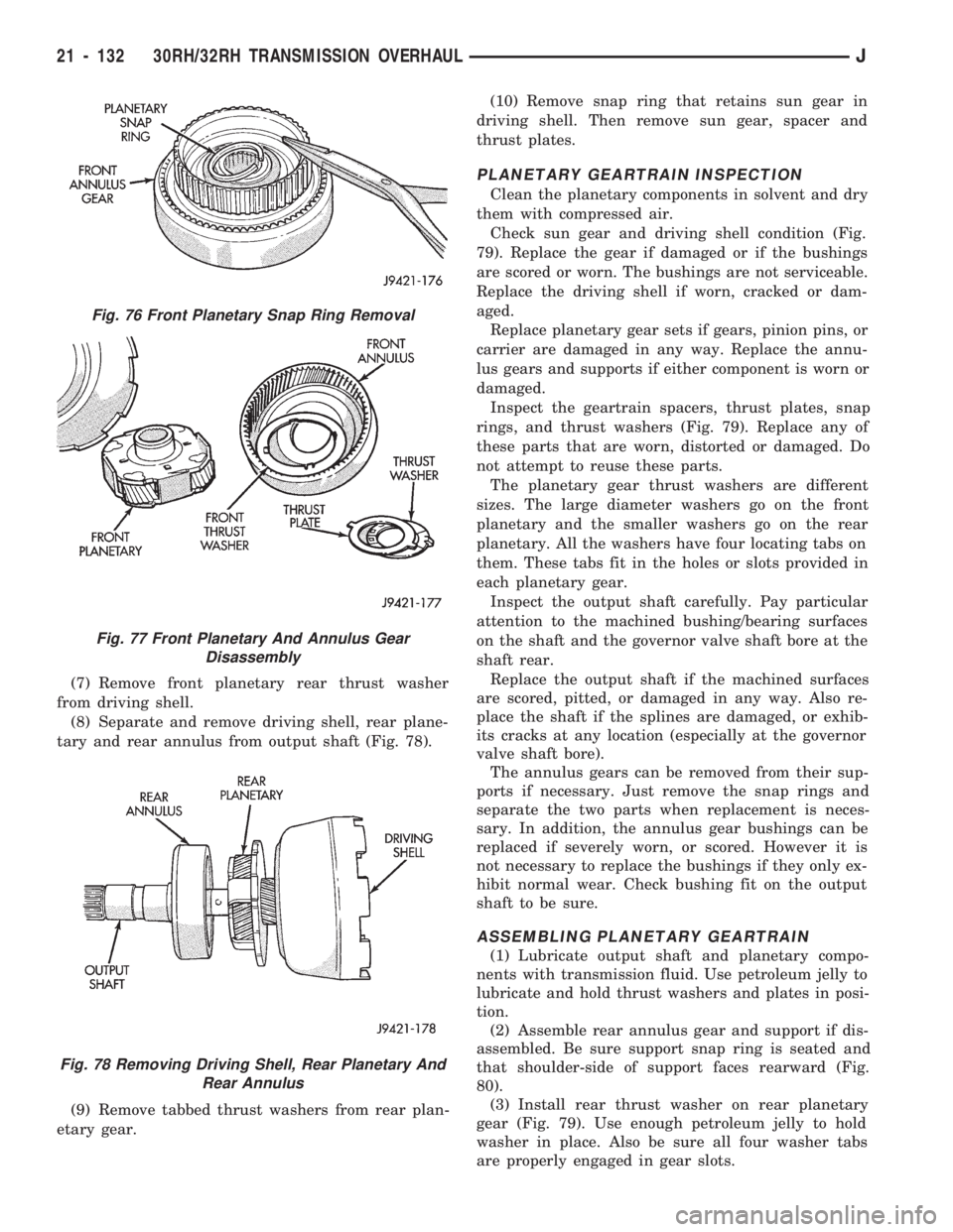
(7) Remove front planetary rear thrust washer
from driving shell.
(8) Separate and remove driving shell, rear plane-
tary and rear annulus from output shaft (Fig. 78).
(9) Remove tabbed thrust washers from rear plan-
etary gear.(10) Remove snap ring that retains sun gear in
driving shell. Then remove sun gear, spacer and
thrust plates.
PLANETARY GEARTRAIN INSPECTION
Clean the planetary components in solvent and dry
them with compressed air.
Check sun gear and driving shell condition (Fig.
79). Replace the gear if damaged or if the bushings
are scored or worn. The bushings are not serviceable.
Replace the driving shell if worn, cracked or dam-
aged.
Replace planetary gear sets if gears, pinion pins, or
carrier are damaged in any way. Replace the annu-
lus gears and supports if either component is worn or
damaged.
Inspect the geartrain spacers, thrust plates, snap
rings, and thrust washers (Fig. 79). Replace any of
these parts that are worn, distorted or damaged. Do
not attempt to reuse these parts.
The planetary gear thrust washers are different
sizes. The large diameter washers go on the front
planetary and the smaller washers go on the rear
planetary. All the washers have four locating tabs on
them. These tabs fit in the holes or slots provided in
each planetary gear.
Inspect the output shaft carefully. Pay particular
attention to the machined bushing/bearing surfaces
on the shaft and the governor valve shaft bore at the
shaft rear.
Replace the output shaft if the machined surfaces
are scored, pitted, or damaged in any way. Also re-
place the shaft if the splines are damaged, or exhib-
its cracks at any location (especially at the governor
valve shaft bore).
The annulus gears can be removed from their sup-
ports if necessary. Just remove the snap rings and
separate the two parts when replacement is neces-
sary. In addition, the annulus gear bushings can be
replaced if severely worn, or scored. However it is
not necessary to replace the bushings if they only ex-
hibit normal wear. Check bushing fit on the output
shaft to be sure.
ASSEMBLING PLANETARY GEARTRAIN
(1) Lubricate output shaft and planetary compo-
nents with transmission fluid. Use petroleum jelly to
lubricate and hold thrust washers and plates in posi-
tion.
(2) Assemble rear annulus gear and support if dis-
assembled. Be sure support snap ring is seated and
that shoulder-side of support faces rearward (Fig.
80).
(3) Install rear thrust washer on rear planetary
gear (Fig. 79). Use enough petroleum jelly to hold
washer in place. Also be sure all four washer tabs
are properly engaged in gear slots.
Fig. 76 Front Planetary Snap Ring Removal
Fig. 77 Front Planetary And Annulus Gear
Disassembly
Fig. 78 Removing Driving Shell, Rear Planetary And
Rear Annulus
21 - 132 30RH/32RH TRANSMISSION OVERHAULJ
Page 1244 of 1784
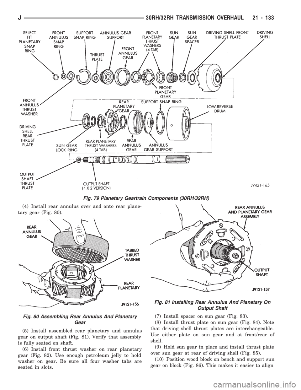
(4) Install rear annulus over and onto rear plane-
tary gear (Fig. 80).
(5) Install assembled rear planetary and annulus
gear on output shaft (Fig. 81). Verify that assembly
is fully seated on shaft.
(6) Install front thrust washer on rear planetary
gear (Fig. 82). Use enough petroleum jelly to hold
washer on gear. Be sure all four washer tabs are
seated in slots.(7) Install spacer on sun gear (Fig. 83).
(8) Install thrust plate on sun gear (Fig. 84). Note
that driving shell thrust plates are interchangeable.
Use either plate on sun gear and at front/rear of
shell.
(9) Hold sun gear in place and install thrust plate
over sun gear at rear of driving shell (Fig. 85).
(10) Position wood block on bench and support sun
gear on block (Fig. 86). This makes it easier to align
Fig. 79 Planetary Geartrain Components (30RH/32RH)
Fig. 80 Assembling Rear Annulus And Planetary
Gear
Fig. 81 Installing Rear Annulus And Planetary On
Output Shaft
J30RH/32RH TRANSMISSION OVERHAUL 21 - 133
Page 1245 of 1784
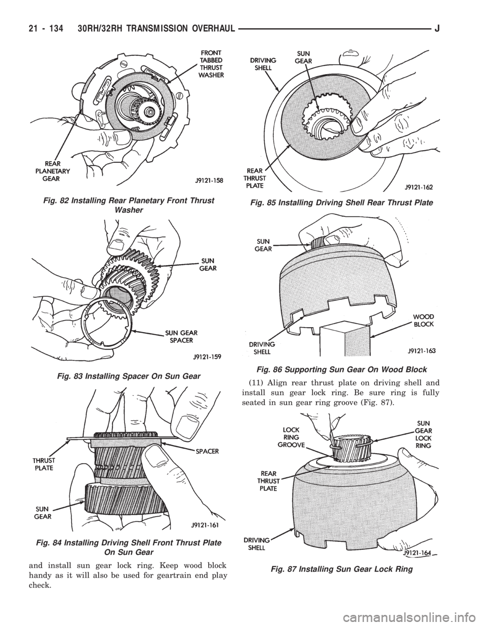
and install sun gear lock ring. Keep wood block
handy as it will also be used for geartrain end play
check.(11) Align rear thrust plate on driving shell and
install sun gear lock ring. Be sure ring is fully
seated in sun gear ring groove (Fig. 87).
Fig. 82 Installing Rear Planetary Front Thrust
Washer
Fig. 83 Installing Spacer On Sun Gear
Fig. 84 Installing Driving Shell Front Thrust Plate
On Sun Gear
Fig. 85 Installing Driving Shell Rear Thrust Plate
Fig. 86 Supporting Sun Gear On Wood Block
Fig. 87 Installing Sun Gear Lock Ring
21 - 134 30RH/32RH TRANSMISSION OVERHAULJ
Page 1246 of 1784
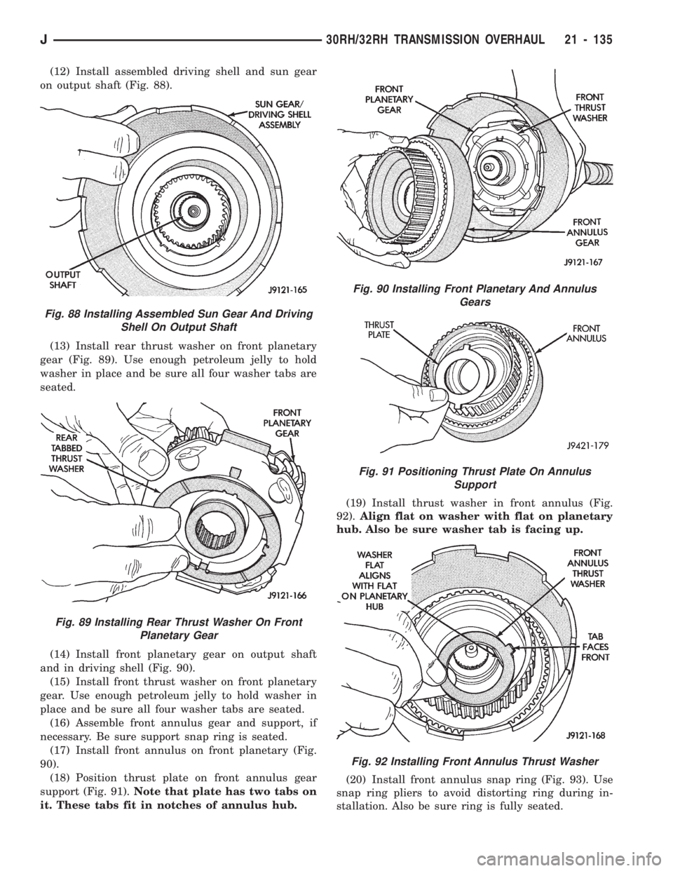
(12) Install assembled driving shell and sun gear
on output shaft (Fig. 88).
(13) Install rear thrust washer on front planetary
gear (Fig. 89). Use enough petroleum jelly to hold
washer in place and be sure all four washer tabs are
seated.
(14) Install front planetary gear on output shaft
and in driving shell (Fig. 90).
(15) Install front thrust washer on front planetary
gear. Use enough petroleum jelly to hold washer in
place and be sure all four washer tabs are seated.
(16) Assemble front annulus gear and support, if
necessary. Be sure support snap ring is seated.
(17) Install front annulus on front planetary (Fig.
90).
(18) Position thrust plate on front annulus gear
support (Fig. 91).Note that plate has two tabs on
it. These tabs fit in notches of annulus hub.(19) Install thrust washer in front annulus (Fig.
92).Align flat on washer with flat on planetary
hub. Also be sure washer tab is facing up.
(20) Install front annulus snap ring (Fig. 93). Use
snap ring pliers to avoid distorting ring during in-
stallation. Also be sure ring is fully seated.
Fig. 88 Installing Assembled Sun Gear And Driving
Shell On Output Shaft
Fig. 89 Installing Rear Thrust Washer On Front
Planetary Gear
Fig. 90 Installing Front Planetary And Annulus
Gears
Fig. 91 Positioning Thrust Plate On Annulus
Support
Fig. 92 Installing Front Annulus Thrust Washer
J30RH/32RH TRANSMISSION OVERHAUL 21 - 135
Page 1247 of 1784
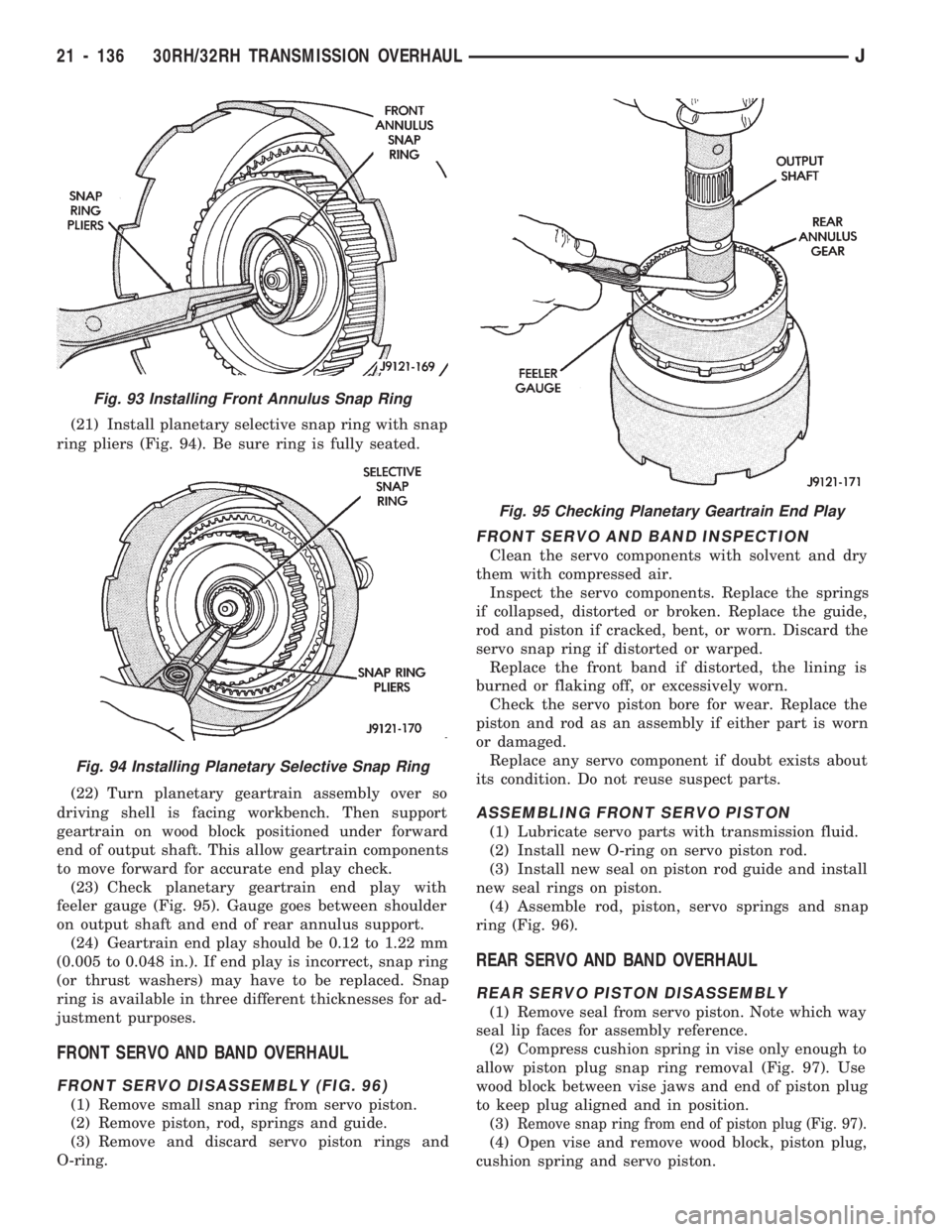
(21) Install planetary selective snap ring with snap
ring pliers (Fig. 94). Be sure ring is fully seated.
(22) Turn planetary geartrain assembly over so
driving shell is facing workbench. Then support
geartrain on wood block positioned under forward
end of output shaft. This allow geartrain components
to move forward for accurate end play check.
(23) Check planetary geartrain end play with
feeler gauge (Fig. 95). Gauge goes between shoulder
on output shaft and end of rear annulus support.
(24) Geartrain end play should be 0.12 to 1.22 mm
(0.005 to 0.048 in.). If end play is incorrect, snap ring
(or thrust washers) may have to be replaced. Snap
ring is available in three different thicknesses for ad-
justment purposes.
FRONT SERVO AND BAND OVERHAUL
FRONT SERVO DISASSEMBLY (FIG. 96)
(1) Remove small snap ring from servo piston.
(2) Remove piston, rod, springs and guide.
(3) Remove and discard servo piston rings and
O-ring.
FRONT SERVO AND BAND INSPECTION
Clean the servo components with solvent and dry
them with compressed air.
Inspect the servo components. Replace the springs
if collapsed, distorted or broken. Replace the guide,
rod and piston if cracked, bent, or worn. Discard the
servo snap ring if distorted or warped.
Replace the front band if distorted, the lining is
burned or flaking off, or excessively worn.
Check the servo piston bore for wear. Replace the
piston and rod as an assembly if either part is worn
or damaged.
Replace any servo component if doubt exists about
its condition. Do not reuse suspect parts.
ASSEMBLING FRONT SERVO PISTON
(1) Lubricate servo parts with transmission fluid.
(2) Install new O-ring on servo piston rod.
(3) Install new seal on piston rod guide and install
new seal rings on piston.
(4) Assemble rod, piston, servo springs and snap
ring (Fig. 96).
REAR SERVO AND BAND OVERHAUL
REAR SERVO PISTON DISASSEMBLY
(1) Remove seal from servo piston. Note which way
seal lip faces for assembly reference.
(2) Compress cushion spring in vise only enough to
allow piston plug snap ring removal (Fig. 97). Use
wood block between vise jaws and end of piston plug
to keep plug aligned and in position.
(3)
Remove snap ring from end of piston plug (Fig. 97).
(4) Open vise and remove wood block, piston plug,
cushion spring and servo piston.
Fig. 93 Installing Front Annulus Snap Ring
Fig. 94 Installing Planetary Selective Snap Ring
Fig. 95 Checking Planetary Geartrain End Play
21 - 136 30RH/32RH TRANSMISSION OVERHAULJ
Page 1248 of 1784
REAR SERVO INSPECTION
Clean the servo components with solvent and dry
them with compressed air.
Check rear band condition. Replace the band if dis-
torted, the lining is burned or flaking off, or the lin-
ing is excessively worn.
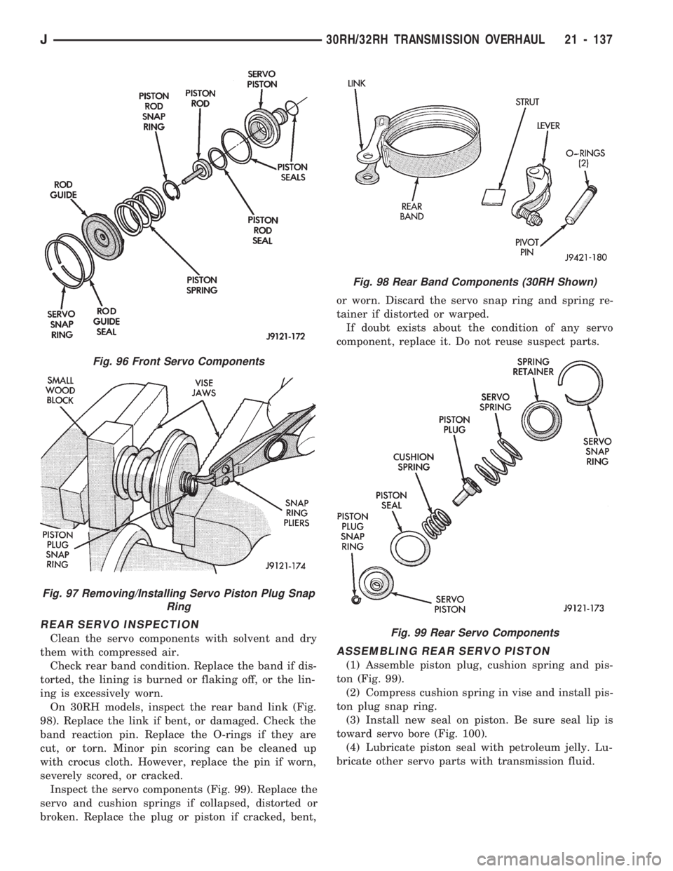
On 30RH models, inspect the rear band link (Fig.
98). Replace the link if bent, or damaged. Check the
band reaction pin. Replace the O-rings if they are
cut, or torn. Minor pin scoring can be cleaned up
with crocus cloth. However, replace the pin if worn,
severely scored, or cracked.
Inspect the servo components (Fig. 99). Replace the
servo and cushion springs if collapsed, distorted or
broken. Replace the plug or piston if cracked, bent,or worn. Discard the servo snap ring and spring re-
tainer if distorted or warped.
If doubt exists about the condition of any servo
component, replace it. Do not reuse suspect parts.
ASSEMBLING REAR SERVO PISTON
(1) Assemble piston plug, cushion spring and pis-
ton (Fig. 99).
(2) Compress cushion spring in vise and install pis-
ton plug snap ring.
(3) Install new seal on piston. Be sure seal lip is
toward servo bore (Fig. 100).
(4) Lubricate piston seal with petroleum jelly. Lu-
bricate other servo parts with transmission fluid.
Fig. 96 Front Servo Components
Fig. 97 Removing/Installing Servo Piston Plug Snap
Ring
Fig. 98 Rear Band Components (30RH Shown)
Fig. 99 Rear Servo Components
J30RH/32RH TRANSMISSION OVERHAUL 21 - 137
Page 1257 of 1784
rect sequence. The correct sequence is line pressure
adjustment first and throttle pressure adjustment
last.
Line Pressure Adjustment
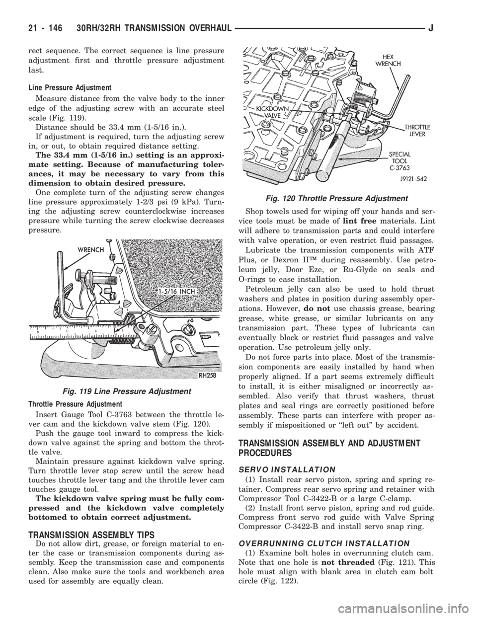
Measure distance from the valve body to the inner
edge of the adjusting screw with an accurate steel
scale (Fig. 119).
Distance should be 33.4 mm (1-5/16 in.).
If adjustment is required, turn the adjusting screw
in, or out, to obtain required distance setting.
The 33.4 mm (1-5/16 in.) setting is an approxi-
mate setting. Because of manufacturing toler-
ances, it may be necessary to vary from this
dimension to obtain desired pressure.
One complete turn of the adjusting screw changes
line pressure approximately 1-2/3 psi (9 kPa). Turn-
ing the adjusting screw counterclockwise increases
pressure while turning the screw clockwise decreases
pressure.
Throttle Pressure Adjustment
Insert Gauge Tool C-3763 between the throttle le-
ver cam and the kickdown valve stem (Fig. 120).
Push the gauge tool inward to compress the kick-
down valve against the spring and bottom the throt-
tle valve.
Maintain pressure against kickdown valve spring.
Turn throttle lever stop screw until the screw head
touches throttle lever tang and the throttle lever cam
touches gauge tool.
The kickdown valve spring must be fully com-
pressed and the kickdown valve completely
bottomed to obtain correct adjustment.
TRANSMISSION ASSEMBLY TIPS
Do not allow dirt, grease, or foreign material to en-
ter the case or transmission components during as-
sembly. Keep the transmission case and components
clean. Also make sure the tools and workbench area
used for assembly are equally clean.Shop towels used for wiping off your hands and ser-
vice tools must be made oflint freematerials. Lint
will adhere to transmission parts and could interfere
with valve operation, or even restrict fluid passages.
Lubricate the transmission components with ATF
Plus, or Dexron IIŸ during reassembly. Use petro-
leum jelly, Door Eze, or Ru-Glyde on seals and
O-rings to ease installation.
Petroleum jelly can also be used to hold thrust
washers and plates in position during assembly oper-
ations. However,do notuse chassis grease, bearing
grease, white grease, or similar lubricants on any
transmission part. These types of lubricants can
eventually block or restrict fluid passages and valve
operation. Use petroleum jelly only.
Do not force parts into place. Most of the transmis-
sion components are easily installed by hand when
properly aligned. If a part seems extremely difficult
to install, it is either misaligned or incorrectly as-
sembled. Also verify that thrust washers, thrust
plates and seal rings are correctly positioned before
assembly. These parts can interfere with proper as-
sembly if mispositioned or ``left out'' by accident.
TRANSMISSION ASSEMBLY AND ADJUSTMENT
PROCEDURES
SERVO INSTALLATION
(1) Install rear servo piston, spring and spring re-
tainer. Compress rear servo spring and retainer with
Compressor Tool C-3422-B or a large C-clamp.
(2) Install front servo piston, spring and rod guide.
Compress front servo rod guide with Valve Spring
Compressor C-3422-B and install servo snap ring.
OVERRUNNING CLUTCH INSTALLATION
(1) Examine bolt holes in overrunning clutch cam.
Note that one hole isnot threaded(Fig. 121). This
hole must align with blank area in clutch cam bolt
circle (Fig. 122).
Fig. 120 Throttle Pressure Adjustment
Fig. 119 Line Pressure Adjustment
21 - 146 30RH/32RH TRANSMISSION OVERHAULJ
Page 1262 of 1784
(7) Rotate output shaft until opposite end of gover-
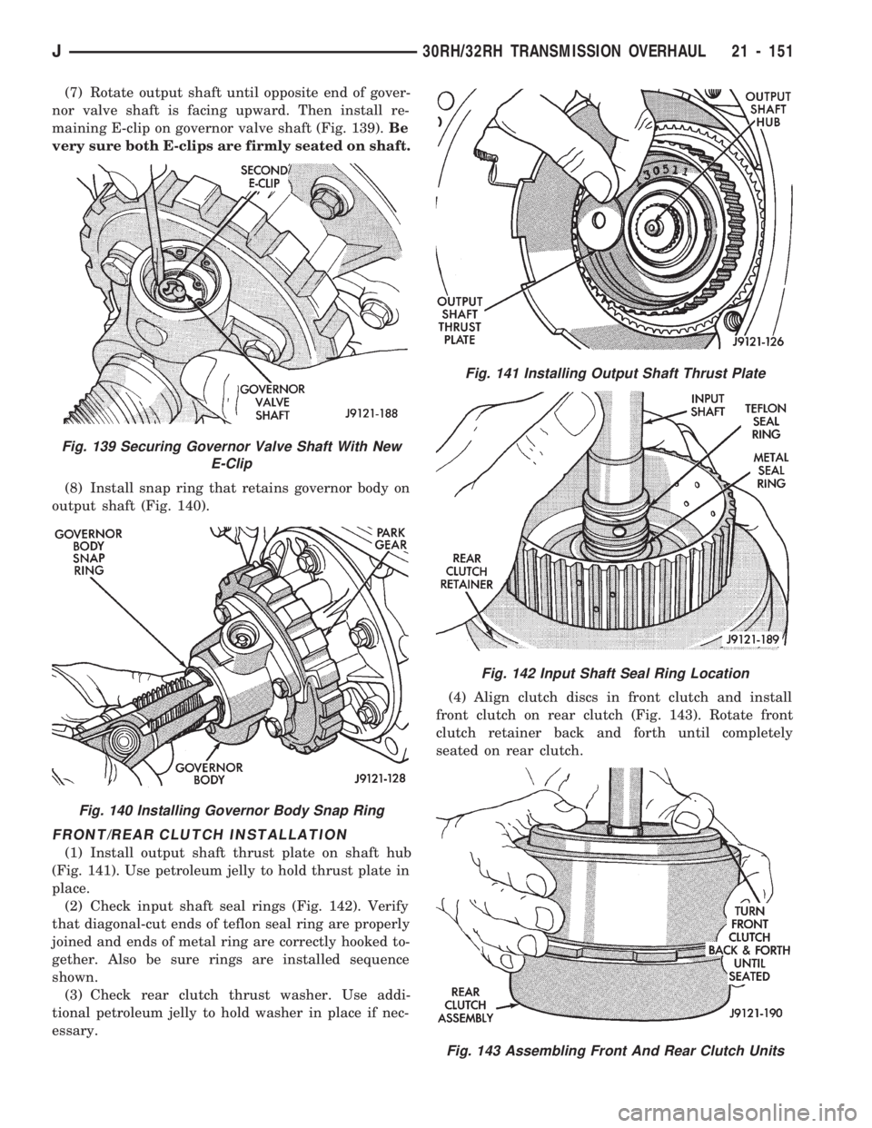
nor valve shaft is facing upward. Then install re-
maining E-clip on governor valve shaft (Fig. 139).Be
very sure both E-clips are firmly seated on shaft.
(8) Install snap ring that retains governor body on
output shaft (Fig. 140).
FRONT/REAR CLUTCH INSTALLATION
(1) Install output shaft thrust plate on shaft hub
(Fig. 141). Use petroleum jelly to hold thrust plate in
place.
(2) Check input shaft seal rings (Fig. 142). Verify
that diagonal-cut ends of teflon seal ring are properly
joined and ends of metal ring are correctly hooked to-
gether. Also be sure rings are installed sequence
shown.
(3) Check rear clutch thrust washer. Use addi-
tional petroleum jelly to hold washer in place if nec-
essary.(4) Align clutch discs in front clutch and install
front clutch on rear clutch (Fig. 143). Rotate front
clutch retainer back and forth until completely
seated on rear clutch.
Fig. 139 Securing Governor Valve Shaft With New
E-Clip
Fig. 140 Installing Governor Body Snap Ring
Fig. 141 Installing Output Shaft Thrust Plate
Fig. 142 Input Shaft Seal Ring Location
Fig. 143 Assembling Front And Rear Clutch Units
J30RH/32RH TRANSMISSION OVERHAUL 21 - 151