Page 1328 of 1784
should move smoothly and not bind or stick. If oper-
ation is incorrect, replace piston and support.
(3) Remove thrust bearing front race, thrust bear-
ing and rear race (Fig. 3).
(4) Turn overdrive support over and remove bear-
ing race and clutch drum thrust washer (Fig. 4).
(5) Compress piston return spring with Spring
Compressor 7537 and remove piston snap ring (Fig.
5).(6) Mount support in direct clutch and remove
brake piston with compressed air. Apply air to same
feed hole used when checking piston operation.
(7) Remove and discard support O-rings (Fig. 1).
Fig. 2 Checking Brake Piston Movement
Fig. 3 Removing Support Thrust Bearing And Races
Fig. 4 Removing Clutch Drum Thrust Washer And
Race
Fig. 5 Removing/Installing Piston Snap Ring
JAW-4 TRANSMISSION OVERHAUL 21 - 217
Page 1329 of 1784

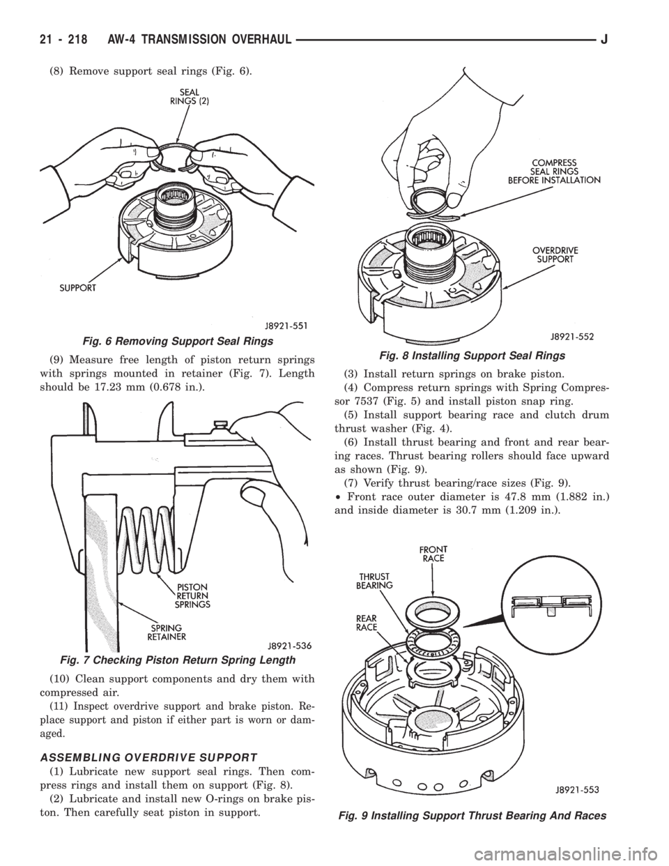
(8) Remove support seal rings (Fig. 6).
(9) Measure free length of piston return springs
with springs mounted in retainer (Fig. 7). Length
should be 17.23 mm (0.678 in.).
(10) Clean support components and dry them with
compressed air.
(11) Inspect overdrive support and brake piston. Re-
place support and piston if either part is worn or dam-
aged.
ASSEMBLING OVERDRIVE SUPPORT
(1) Lubricate new support seal rings. Then com-
press rings and install them on support (Fig. 8).
(2) Lubricate and install new O-rings on brake pis-
ton. Then carefully seat piston in support.(3) Install return springs on brake piston.
(4) Compress return springs with Spring Compres-
sor 7537 (Fig. 5) and install piston snap ring.
(5) Install support bearing race and clutch drum
thrust washer (Fig. 4).
(6) Install thrust bearing and front and rear bear-
ing races. Thrust bearing rollers should face upward
as shown (Fig. 9).
(7) Verify thrust bearing/race sizes (Fig. 9).
²Front race outer diameter is 47.8 mm (1.882 in.)
and inside diameter is 30.7 mm (1.209 in.).
Fig. 9 Installing Support Thrust Bearing And Races
Fig. 6 Removing Support Seal Rings
Fig. 7 Checking Piston Return Spring Length
Fig. 8 Installing Support Seal Rings
21 - 218 AW-4 TRANSMISSION OVERHAULJ
Page 1339 of 1784

FRONT PLANETARY GEAR OVERHAUL
FRONT PLANETARY DISASSEMBLY
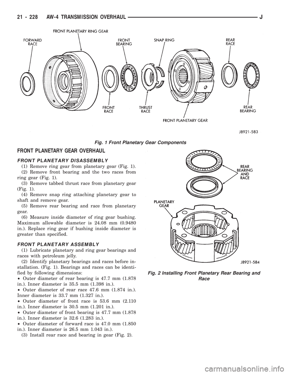
(1) Remove ring gear from planetary gear (Fig. 1).
(2) Remove front bearing and the two races from
ring gear (Fig. 1).
(3) Remove tabbed thrust race from planetary gear
(Fig. 1).
(4) Remove snap ring attaching planetary gear to
shaft and remove gear.
(5) Remove rear bearing and race from planetary
gear.
(6) Measure inside diameter of ring gear bushing.
Maximum allowable diameter is 24.08 mm (0.9480
in.). Replace ring gear if bushing inside diameter is
greater than specified.
FRONT PLANETARY ASSEMBLY
(1) Lubricate planetary and ring gear bearings and
races with petroleum jelly.
(2) Identify planetary bearings and races before in-
stallation. (Fig. 1). Bearings and races can be identi-
fied by following dimensions:
²Outer diameter of rear bearing is 47.7 mm (1.878
in.). Inner diameter is 35.5 mm (1.398 in.).
²Outer diameter of rear race 47.6 mm (1.874 in.).
Inner diameter is 33.7 mm (1.327 in.).
²Outer diameter of front race is 53.6 mm (2.110
in.). Inner diameter is 30.5 mm (1.201 in.).
²Outer diameter of front bearing is 47.7 mm (1.878
in.). Inner diameter is 32.6 (1.283 in.).
²Outer diameter of forward race is 47.0 mm (1.850
in.). Inner diameter is 26.5 mm 1.043 in.).
(3) Install rear race and bearing in gear (Fig. 2).
Fig. 1 Front Planetary Gear Components
Fig. 2 Installing Front Planetary Rear Bearing and
Race
21 - 228 AW-4 TRANSMISSION OVERHAULJ
Page 1340 of 1784
(4) Turn planetary over and install race thrust
race (Fig. 3).
(5) Install front race and bearing and forward race
in ring gear (Fig. 4).
(6) Set planetary gear assembly aside for final as-
sembly.
SUN GEAR AND NO. 1 ONE-WAY CLUTCH
OVERHAUL
SUN GEAR AND CLUTCH DISASSEMBLY
(1) Hold sun gear and turn second brake hub
clockwise and counterclockwise (Fig. 2). Hub should
rotate freely clockwise but lock when turned counter-clockwise. Replace one-way clutch and hub if they do
not operate properly.
(2) Remove one-way clutch/second brake hub as-
sembly from drum (Fig. 3).
(3) Remove thrust washer from drum (Fig. 4).
(4) Remove two seal rings from sun gear (Fig. 5).
Fig. 1 Sun Gear And One-Way Clutch Components
Fig. 3 Installing Front Planetary Thrust Race
Fig. 4 Installing Front Planetary Front Bearing And
Races
JAW-4 TRANSMISSION OVERHAUL 21 - 229
Page 1346 of 1784
(7) Remove clutch inner race from planetary gear
(Fig. 7).
(8) Remove clutch snap ring and remove No. 2 one-
way clutch from planetary (Fig. 8).
(9) Remove front and rear thrust washers from
planetary gear (Fig. 9).
(10) Remove thrust bearing and washers from ring
gear (Fig. 10).
(11) Remove ring gear snap ring and remove ring
gear hub (Fig. 11).
(12) Inspect and replace any worn or damaged
planetary gear components.
Fig. 7 Removing/Installing Clutch Inner Race
Fig. 5 Removing/Installing Rear Planetary
Fig. 3 Removing/Installing Shaft Seal Ring
Fig. 4 Removing/Installing First-Reverse Brake Pack
Fig. 6 Checking No. 2 One-Way Clutch Operation
JAW-4 TRANSMISSION OVERHAUL 21 - 235
Page 1367 of 1784

(4) Install rear planetary gear, second brake drum
and output shaft as outlined in following steps:
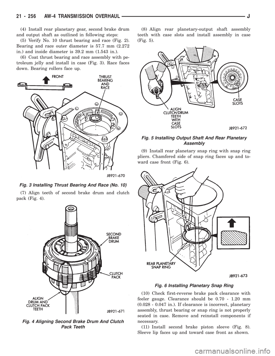
(5) Verify No. 10 thrust bearing and race (Fig. 2).
Bearing and race outer diameter is 57.7 mm (2.272
in.) and inside diameter is 39.2 mm (1.543 in.).
(6) Coat thrust bearing and race assembly with pe-
troleum jelly and install in case (Fig. 3). Race faces
down. Bearing rollers face up.
(7) Align teeth of second brake drum and clutch
pack (Fig. 4).(8) Align rear planetary-output shaft assembly
teeth with case slots and install assembly in case
(Fig. 5).
(9) Install rear planetary snap ring with snap ring
pliers. Chamfered side of snap ring faces up and to-
ward case front (Fig. 6).
(10) Check first-reverse brake pack clearance with
feeler gauge. Clearance should be 0.70 - 1.20 mm
(0.028 - 0.047 in.). If clearance is incorrect, planetary
assembly, thrust bearing or snap ring is not properly
seated in case. Remove and reinstall components if
necessary.
(11) Install second brake piston sleeve (Fig. 8).
Sleeve lip faces up and toward case front as shown.
Fig. 3 Installing Thrust Bearing And Race (No. 10)
Fig. 4 Aligning Second Brake Drum And Clutch
Pack Teeth
Fig. 5 Installing Output Shaft And Rear Planetary
Assembly
Fig. 6 Installing Planetary Snap Ring
21 - 256 AW-4 TRANSMISSION OVERHAULJ
Page 1369 of 1784
(17) Install No. 1 one-way clutch (Fig. 14). Short
flanged side of clutch faces up and toward case front.
(18) Install second brake pack (Fig. 15). Install
disc then plate. Continue installation sequence until
correct number of discs-plates are installed. Use five
discs and five plates.
(19) Install second brake pack retainer with
rounded edge of retainer facing disc.
(20) Install second brake pack snap ring.
(21) Check brake pack clearance with feeler gauge
(Fig. 16). Clearance should be 0.062 - 1.98 mm (0.024
- 0.078 in.). If brake pack clearance is not correct,
brake pack components are not seated. Reassemble
brake pack if necessary.
Fig. 14 Installing No. 1 One-Way Clutch
Fig. 12 Installing Park Rod Bracket
Fig. 13 Checking Park Pawl Engagement
Fig. 15 Installing Second Brake Pack
Fig. 16 Checking Second Brake Pack Clearance
21 - 258 AW-4 TRANSMISSION OVERHAULJ
Page 1370 of 1784

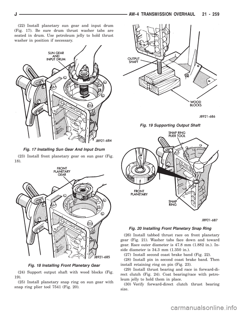
(22) Install planetary sun gear and input drum
(Fig. 17). Be sure drum thrust washer tabs are
seated in drum. Use petroleum jelly to hold thrust
washer in position if necessary.
(23) Install front planetary gear on sun gear (Fig.
18).
(24) Support output shaft with wood blocks (Fig.
19).
(25) Install planetary snap ring on sun gear with
snap ring plier tool 7541 (Fig. 20).(26) Install tabbed thrust race on front planetary
gear (Fig. 21). Washer tabs face down and toward
gear. Race outer diameter is 47.8 mm (1.882 in.). In-
side diameter is 34.3 mm (1.350 in.).
(27) Install second coast brake band (Fig. 22).
(28) Install pin in second coast brake band. Then
install retaining ring on pin (Fig. 23).
(29) Install thrust bearing and race in forward-di-
rect clutch (Fig. 24). Coat bearing/race with petro-
leum jelly to hold them in place.
(30) Verify forward-direct clutch thrust bearing
size.
Fig. 17 Installing Sun Gear And Input Drum
Fig. 18 Installing Front Planetary Gear
Fig. 19 Supporting Output Shaft
Fig. 20 Installing Front Planetary Snap Ring
JAW-4 TRANSMISSION OVERHAUL 21 - 259