Page 1460 of 1784

INSTALLATION
(1) Place the grille opening panel (GOP) on bumper
and connect all front lamp wire harness connectors.
(2) Position the grille opening panel (GOP) on the
vehicle and install the side and upper nuts. Tighten
nuts to 7 Nzm (58 in-lbs) torque.
(3) Install the screw to attach grille opening panel
(GOP) to the crossmember support bracket. Tighten
the screw to 1 Nzm (11 in-lbs) torque.
(4) Install headlamps and park/turn signal lamps
in GOP.(5) Install the headlamp bezels on the GOP.
Tighten the screws to 1 Nzm (13 in-lbs) torque.
(6) Install the side marker lenses and screws on
the grille opening panel (GOP). Tighten the screws to
1Nzm (13 in-lbs) torque.
(7) Install the grille on the GOP. Tighten screws to
1Nzm (13 in-lbs) torque.
(8) Adjust the headlamp aim, if necessary. Refer to
the headlamp beam adjustment procedure within
Group 8L.
RADIATOR SUPPORT CROSSMEMBER
REMOVAL
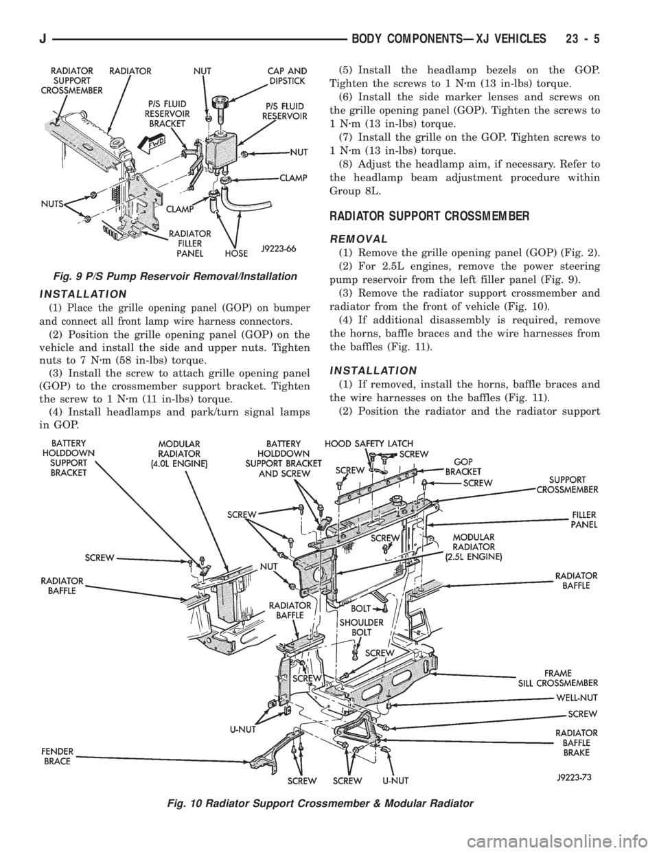
(1) Remove the grille opening panel (GOP) (Fig. 2).
(2) For 2.5L engines, remove the power steering
pump reservoir from the left filler panel (Fig. 9).
(3) Remove the radiator support crossmember and
radiator from the front of vehicle (Fig. 10).
(4) If additional disassembly is required, remove
the horns, baffle braces and the wire harnesses from
the baffles (Fig. 11).
INSTALLATION
(1) If removed, install the horns, baffle braces and
the wire harnesses on the baffles (Fig. 11).
(2) Position the radiator and the radiator support
Fig. 9 P/S Pump Reservoir Removal/Installation
Fig. 10 Radiator Support Crossmember & Modular Radiator
JBODY COMPONENTSÐXJ VEHICLES 23 - 5
Page 1461 of 1784
crossmember at the front of vehicle (Fig. 10). Install
and tighten screws to 9 Nzm (76 in-lbs) torque.
(3) For 2.5L engines, install the power steering
pump reservoir on the left filler panel (Fig. 9).
(4) Install the grille opening panel (GOP).
HOOD
The hood service procedures included in this sec-
tion include:
²hood removal and installation;
²hood adjustment;
²hingeÐlatchÐstriker service; and
²latch release cable service.
Refer to Figures 12Ð16 for the hood component
reference.
Fig. 11 Horns, Baffle Braces & Wire Harnesses
23 - 6 BODY COMPONENTSÐXJ VEHICLESJ
Page 1469 of 1784
FRONT FENDER
The following information includes procedures for
removal/installation of:
²a fender liner,
²a front fender flare and retainers, and
²a front fender.
REMOVAL
(1) Remove the front bumper.
(2) Right fender only:
²if equipped, remove the radio antenna mast, and
components from the fender (Figs. 34 and 35);
²remove the battery and tray from the fender inner
panel (Figs. 36, 37 and 38);
²remove windshield washer reservoir from fender
inner panel (Fig. 39);
²remove the hood ajar switch, if equipped, from
fender (Figs. 40 and 41);
²remove the Power Distribution Center (PDC), the
coolant recovery bottle and speed servo from fender
the inner panel.
Fig. 36 Battery, Speed Servo, PDC & Coolant
Recovery Bottle
Fig. 37 Battery Removal/Installation
Fig. 38 Battery Tray Removal/Installation
Fig. 34 Radio Antenna Removal/Installation
Fig. 35 Power Antenna Wire Harness & Cable
Connectors
23 - 14 BODY COMPONENTSÐXJ VEHICLESJ
Page 1470 of 1784
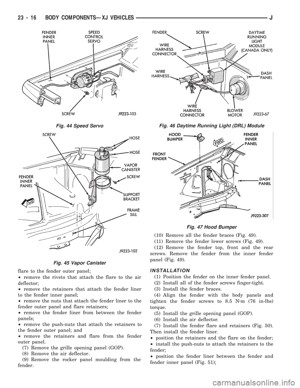
²remove the vapor canister from the fender inner
panel (Figs. 42 and 45);
²remove the A/C Receiver/Drier from the fender in-
ner panel (Fig. 40); and
²if equipped, remove the Daytime Running Light
(DRL) module from the fender inner panel (Fig. 46).
²support the hood and remove the hood support rod
from the fender inner panel.
(3) Remove the hood bumper from the fender inner
panel (Fig. 47).
(4) Raise and support the vehicle.
(5) Remove the front wheel.
(6) Remove the fender liner, fender flare and re-
tainers (Fig. 48):
²remove the screws that attach the lower part of
Fig. 41 Hood Ajar Switch Removal/Installation
Fig. 42 Power Distribution Center and Vapor Canister
Fig. 43 Coolant Recovery Bottle
Fig. 39 Coolant Recovery Bottle, Windshield Washer
Fluid Reservoir & Hood Support Rod
Fig. 40 Hood Ajar Switch, Speed Servo & A/C
Receiver/Drier
JBODY COMPONENTSÐXJ VEHICLES 23 - 15
Page 1471 of 1784

flare to the fender outer panel;
²remove the rivets that attach the flare to the air
deflector;
²remove the retainers that attach the fender liner
to the fender inner panel;
²remove the nuts that attach the fender liner to the
fender outer panel and flare retainers;
²remove the fender liner from between the fender
panels;
²remove the push-nuts that attach the retainers to
the fender outer panel; and
²remove the retainers and flare from the fender
outer panel.
(7) Remove the grille opening panel (GOP).
(8) Remove the air deflector.
(9) Remove the rocker panel moulding from the
fender.(10) Remove all the fender braces (Fig. 49).
(11) Remove the fender lower screws (Fig. 49).
(12) Remove the fender top, front and the rear
screws. Remove the fender from the inner fender
panel (Fig. 49).INSTALLATION
(1) Position the fender on the inner fender panel.
(2) Install all of the fender screws finger-tight.
(3) Install the fender braces.
(4) Align the fender with the body panels and
tighten the fender screws to 8.5 Nzm (76 in-lbs)
torque.
(5) Install the grille opening panel (GOP).
(6) Install the air deflector.
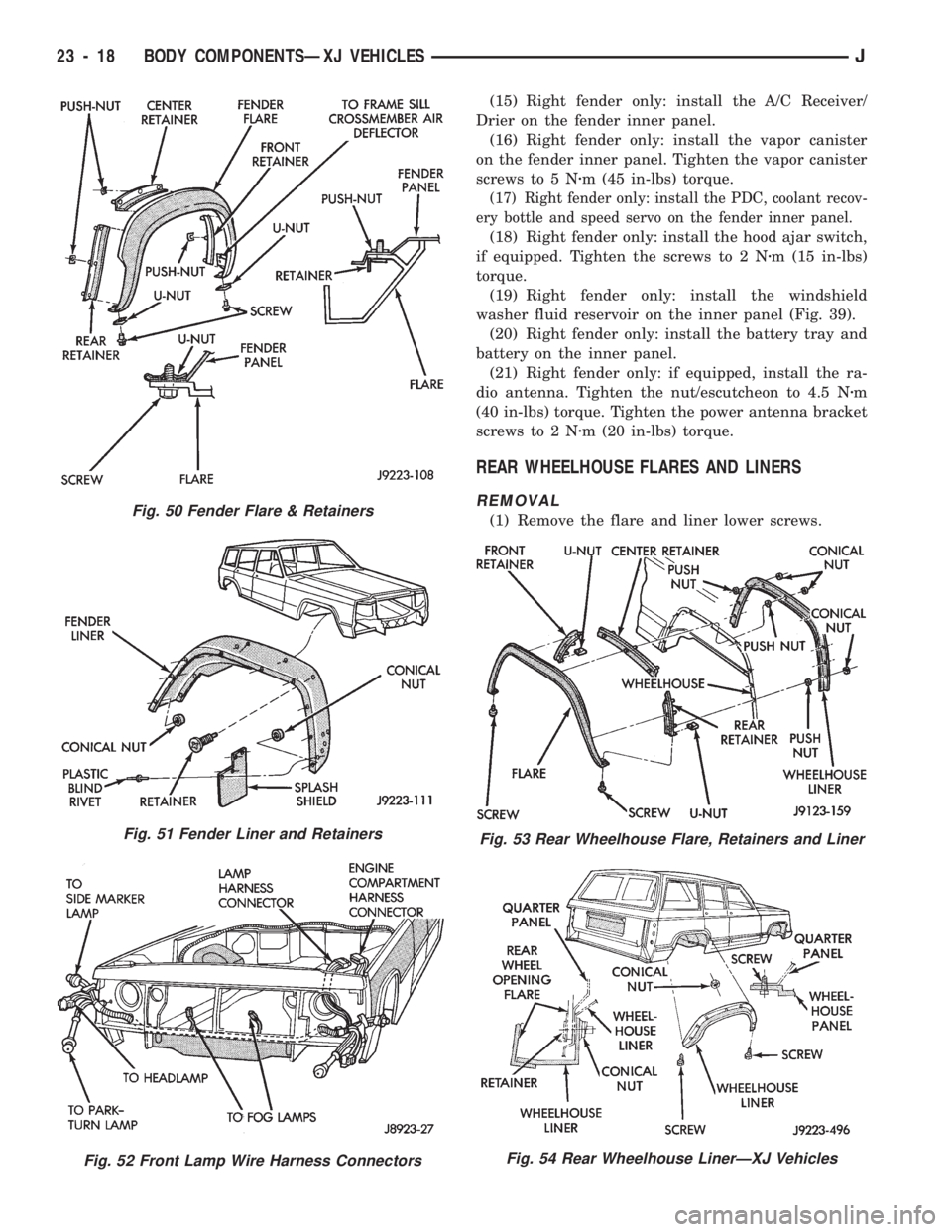
(7) Install the fender flare and retainers (Fig. 50).
Then install the fender liner.
²position the retainers and the flare on the fender;
²install the push-nuts to attach the retainers to the
fender;
²position the fender liner between the fender and
fender inner panel (Fig. 51);
Fig. 44 Speed Servo
Fig. 45 Vapor Canister
Fig. 46 Daytime Running Light (DRL) Module
Fig. 47 Hood Bumper
23 - 16 BODY COMPONENTSÐXJ VEHICLESJ
Page 1472 of 1784
²install the nuts to attach the fender liner to the
fender and flare retainers (Fig. 48);
²install the retainers to attach the fender liner to
the fender inner panel;
²install the rivets to attach the flare to the air de-
flector (Figs. 48 and 50); and
²install the screws to attach the flare to the fender.
Tighten the screws to 1 Nzm (13 in-lbs) torque.
(8) Connect the front lamp wire harness connectors
to the engine wire harness connectors (Fig. 52).(9) Install the front lamps.
(10) Install the front bumper.
(11) Install the wheel, remove the support and
lower the vehicle.
(12) Right fender only: install the hood support rod
on the fender inner panel.
(13) Install the hood bumper on the fender inner
panel.
(14) Right fender only: install the Daytime Run-
ning Light (DRL) module on fender inner panel.
Fig. 48 Fender Flare & Liner Removal/Installation
Fig. 49 Fender Removal/Installation
JBODY COMPONENTSÐXJ VEHICLES 23 - 17
Page 1473 of 1784

(15) Right fender only: install the A/C Receiver/
Drier on the fender inner panel.
(16) Right fender only: install the vapor canister
on the fender inner panel. Tighten the vapor canister
screws to 5 Nzm (45 in-lbs) torque.
(17) Right fender only: install the PDC, coolant recov-
ery bottle and speed servo on the fender inner panel.
(18) Right fender only: install the hood ajar switch,
if equipped. Tighten the screws to 2 Nzm (15 in-lbs)
torque.
(19) Right fender only: install the windshield
washer fluid reservoir on the inner panel (Fig. 39).
(20) Right fender only: install the battery tray and
battery on the inner panel.
(21) Right fender only: if equipped, install the ra-
dio antenna. Tighten the nut/escutcheon to 4.5 Nzm
(40 in-lbs) torque. Tighten the power antenna bracket
screws to 2 Nzm (20 in-lbs) torque.
REAR WHEELHOUSE FLARES AND LINERS
REMOVAL
(1) Remove the flare and liner lower screws.Fig. 50 Fender Flare & Retainers
Fig. 51 Fender Liner and Retainers
Fig. 52 Front Lamp Wire Harness Connectors
Fig. 53 Rear Wheelhouse Flare, Retainers and Liner
Fig. 54 Rear Wheelhouse LinerÐXJ Vehicles
23 - 18 BODY COMPONENTSÐXJ VEHICLESJ
Page 1475 of 1784

²tubular clips,
²screws,
²nuts, and
²rivets.
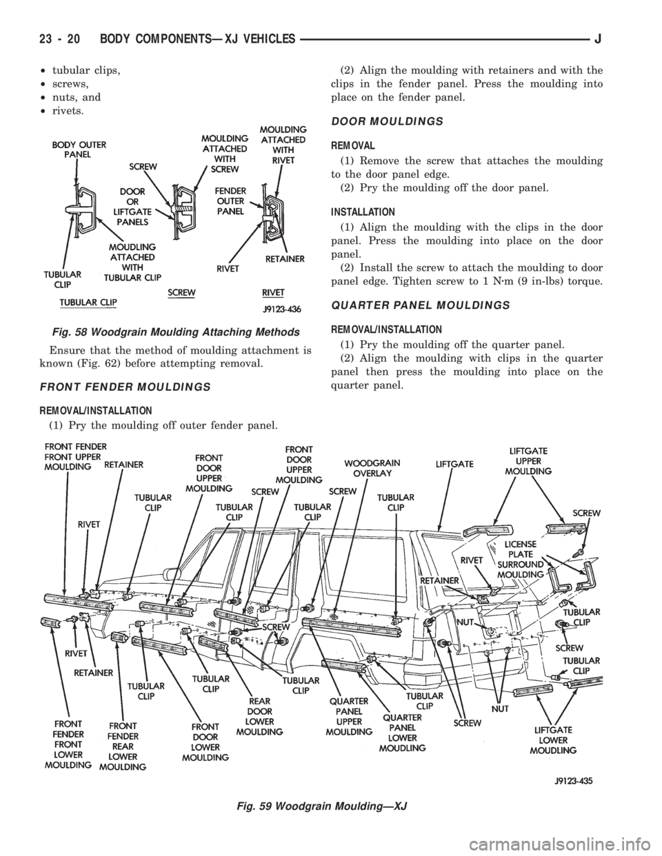
Ensure that the method of moulding attachment is
known (Fig. 62) before attempting removal.
FRONT FENDER MOULDINGS
REMOVAL/INSTALLATION
(1) Pry the moulding off outer fender panel.(2) Align the moulding with retainers and with the
clips in the fender panel. Press the moulding into
place on the fender panel.
DOOR MOULDINGS
REMOVAL
(1) Remove the screw that attaches the moulding
to the door panel edge.
(2) Pry the moulding off the door panel.
INSTALLATION
(1) Align the moulding with the clips in the door
panel. Press the moulding into place on the door
panel.
(2) Install the screw to attach the moulding to door
panel edge. Tighten screw to 1 Nzm (9 in-lbs) torque.
QUARTER PANEL MOULDINGS
REMOVAL/INSTALLATION
(1) Pry the moulding off the quarter panel.
(2) Align the moulding with clips in the quarter
panel then press the moulding into place on the
quarter panel.
Fig. 59 Woodgrain MouldingÐXJ
Fig. 58 Woodgrain Moulding Attaching Methods
23 - 20 BODY COMPONENTSÐXJ VEHICLESJ