Page 1495 of 1784
DOOR REMOVAL/INSTALLATION
REMOVAL
(1) Remove the door restraint (check) retaining pin
(Fig. 24) with a punch.
(2) For vehicles equipped with power windows and
power door locks, remove the trim panel and discon-
nect all components. Slide the wire harness out of
the boot and door.
(3) Remove the door hinge bolts, plates and shims
(Fig. 30). Remove the door from the vehicle.
(4) Identify and retain the door hinge plates and
the shims for correct installation (Fig. 30).
Fig. 24 Door Restraint Retaining Pin
Fig. 25 XJ Right Front Door Wire Harness
Connectors
Fig. 26 XJ Right Front Door Wire Harness
ConnectorsÐWith Security Alarm Switch
Fig. 27 XJ Left Front Door Wire Harness Connectors
23 - 40 BODY COMPONENTSÐXJ VEHICLESJ
Page 1497 of 1784

INSTALLATION
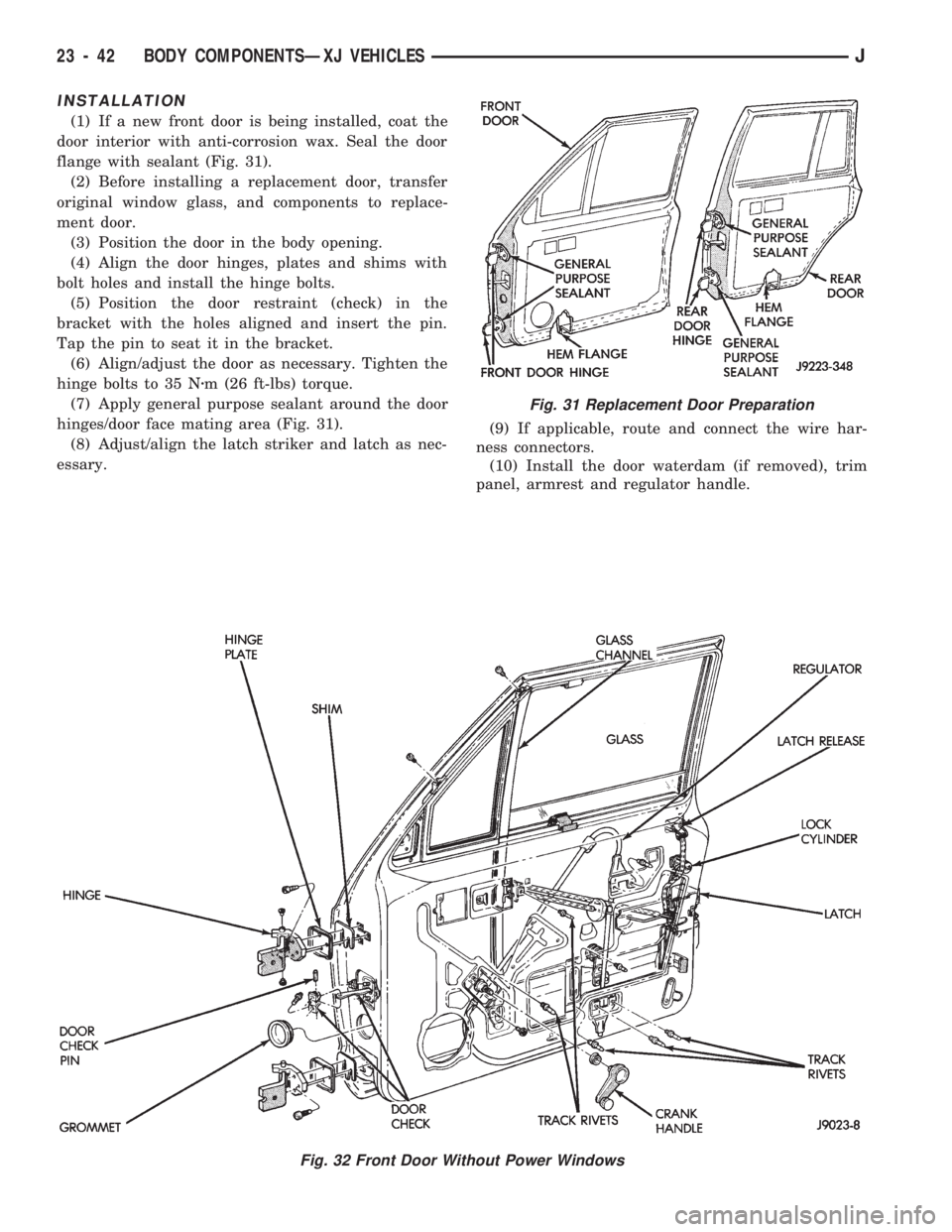
(1) If a new front door is being installed, coat the
door interior with anti-corrosion wax. Seal the door
flange with sealant (Fig. 31).
(2) Before installing a replacement door, transfer
original window glass, and components to replace-
ment door.
(3) Position the door in the body opening.
(4) Align the door hinges, plates and shims with
bolt holes and install the hinge bolts.
(5) Position the door restraint (check) in the
bracket with the holes aligned and insert the pin.
Tap the pin to seat it in the bracket.
(6) Align/adjust the door as necessary. Tighten the
hinge bolts to 35 Nzm (26 ft-lbs) torque.
(7) Apply general purpose sealant around the door
hinges/door face mating area (Fig. 31).
(8) Adjust/align the latch striker and latch as nec-
essary.(9) If applicable, route and connect the wire har-
ness connectors.
(10) Install the door waterdam (if removed), trim
panel, armrest and regulator handle.
Fig. 32 Front Door Without Power Windows
Fig. 31 Replacement Door Preparation
23 - 42 BODY COMPONENTSÐXJ VEHICLESJ
Page 1498 of 1784
Fig. 33 Front Door With Power Windows
JBODY COMPONENTSÐXJ VEHICLES 23 - 43
Page 1502 of 1784

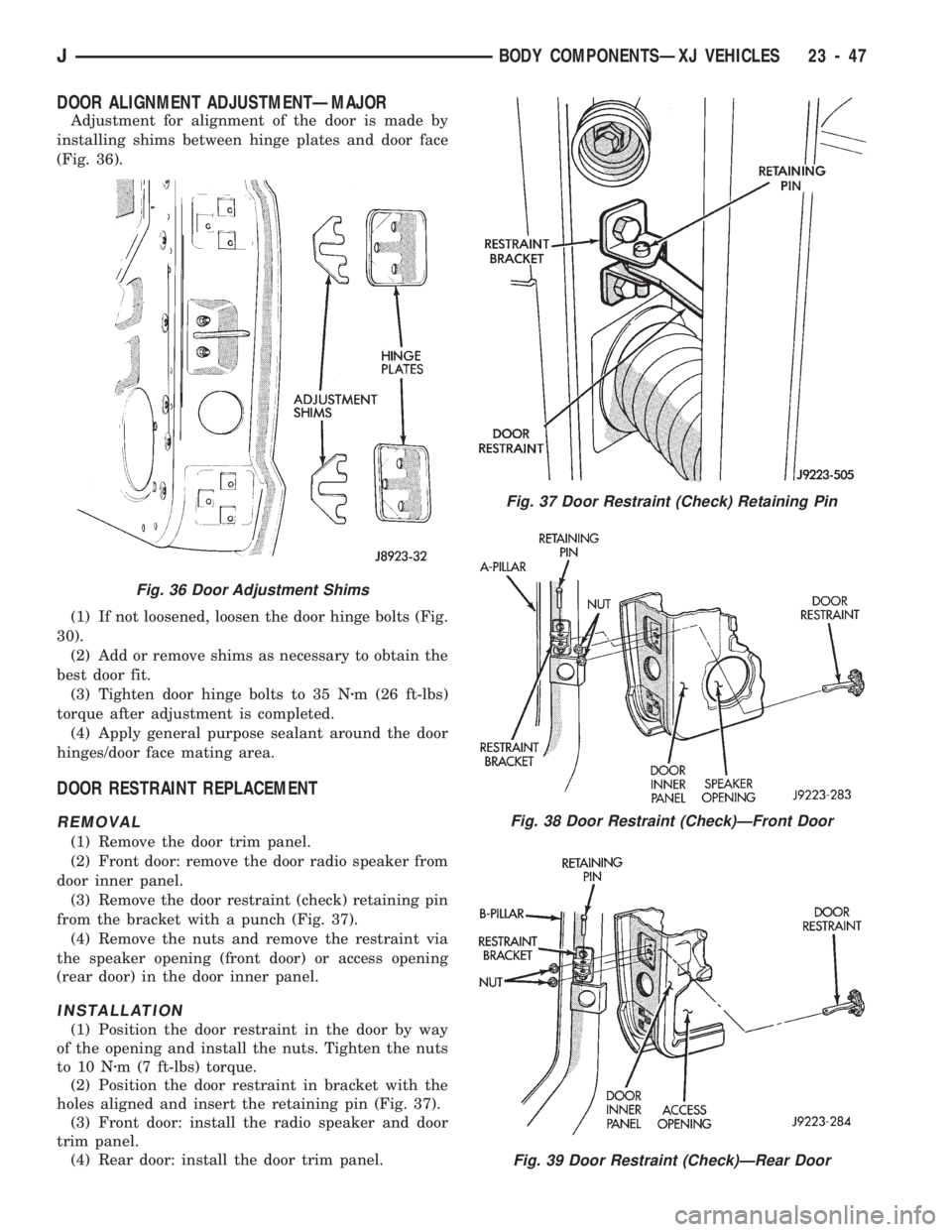
DOOR ALIGNMENT ADJUSTMENTÐMAJOR
Adjustment for alignment of the door is made by
installing shims between hinge plates and door face
(Fig. 36).
(1) If not loosened, loosen the door hinge bolts (Fig.
30).
(2) Add or remove shims as necessary to obtain the
best door fit.
(3) Tighten door hinge bolts to 35 Nzm (26 ft-lbs)
torque after adjustment is completed.
(4) Apply general purpose sealant around the door
hinges/door face mating area.
DOOR RESTRAINT REPLACEMENT
REMOVAL
(1) Remove the door trim panel.
(2) Front door: remove the door radio speaker from
door inner panel.
(3) Remove the door restraint (check) retaining pin
from the bracket with a punch (Fig. 37).
(4) Remove the nuts and remove the restraint via
the speaker opening (front door) or access opening
(rear door) in the door inner panel.
INSTALLATION
(1) Position the door restraint in the door by way
of the opening and install the nuts. Tighten the nuts
to 10 Nzm (7 ft-lbs) torque.
(2) Position the door restraint in bracket with the
holes aligned and insert the retaining pin (Fig. 37).
(3) Front door: install the radio speaker and door
trim panel.
(4) Rear door: install the door trim panel.
Fig. 37 Door Restraint (Check) Retaining Pin
Fig. 38 Door Restraint (Check)ÐFront Door
Fig. 39 Door Restraint (Check)ÐRear Door
Fig. 36 Door Adjustment Shims
JBODY COMPONENTSÐXJ VEHICLES 23 - 47
Page 1503 of 1784

FRONT DOOR WINDOW GLASS REGULATOR
REMOVAL
(1) Remove the door trim panel and waterdam.
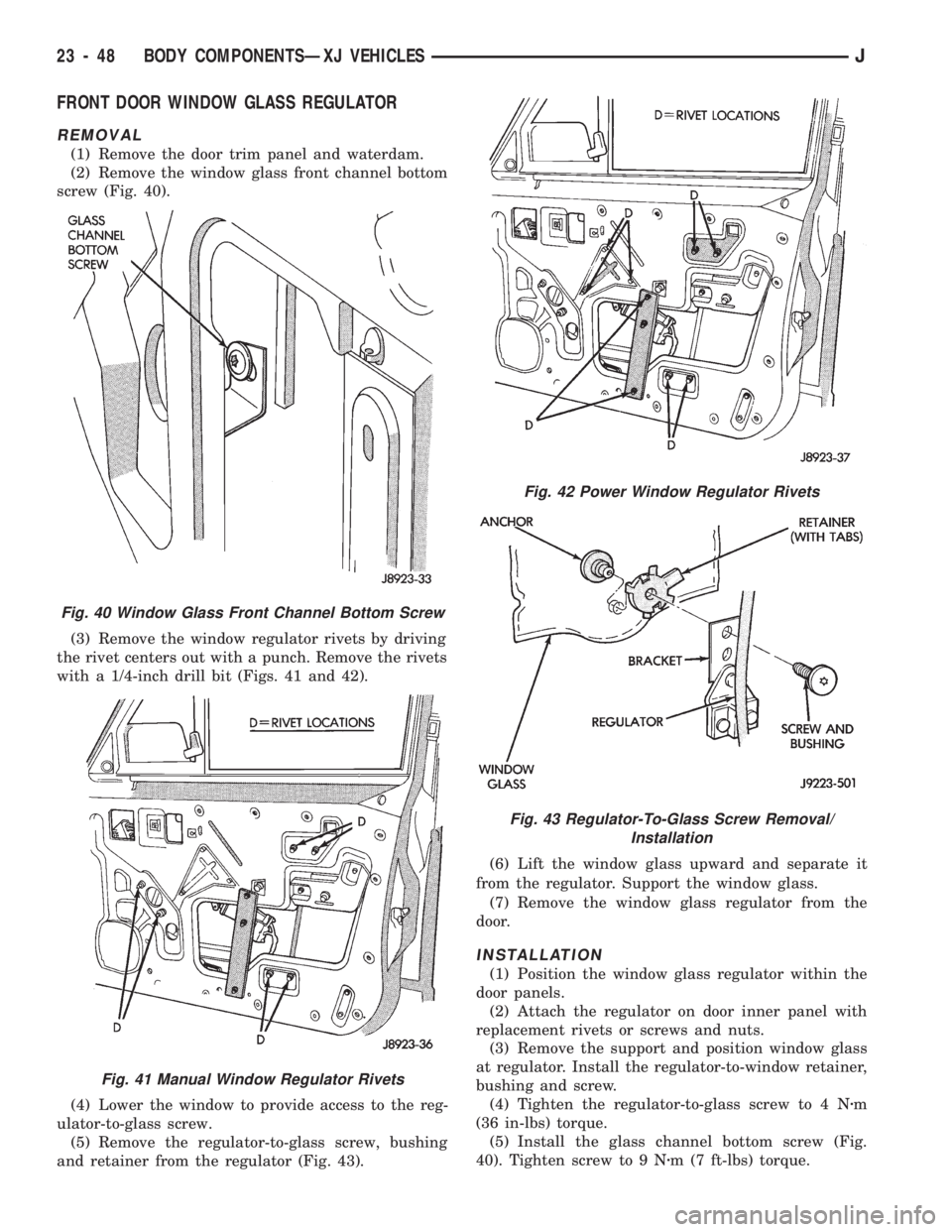
(2) Remove the window glass front channel bottom
screw (Fig. 40).
(3) Remove the window regulator rivets by driving
the rivet centers out with a punch. Remove the rivets
with a 1/4-inch drill bit (Figs. 41 and 42).
(4) Lower the window to provide access to the reg-
ulator-to-glass screw.
(5) Remove the regulator-to-glass screw, bushing
and retainer from the regulator (Fig. 43).(6) Lift the window glass upward and separate it
from the regulator. Support the window glass.
(7) Remove the window glass regulator from the
door.
INSTALLATION
(1) Position the window glass regulator within the
door panels.
(2) Attach the regulator on door inner panel with
replacement rivets or screws and nuts.
(3) Remove the support and position window glass
at regulator. Install the regulator-to-window retainer,
bushing and screw.
(4) Tighten the regulator-to-glass screw to 4 Nzm
(36 in-lbs) torque.
(5) Install the glass channel bottom screw (Fig.
40). Tighten screw to 9 Nzm (7 ft-lbs) torque.
Fig. 40 Window Glass Front Channel Bottom Screw
Fig. 41 Manual Window Regulator Rivets
Fig. 42 Power Window Regulator Rivets
Fig. 43 Regulator-To-Glass Screw Removal/
Installation
23 - 48 BODY COMPONENTSÐXJ VEHICLESJ
Page 1504 of 1784
(6) Attach the door waterdam to the door inner
panel with sealant.
(7) Install the trim panel.
FRONT DOOR WINDOW GLASS
REMOVAL
(1) Remove the door trim panel and waterdam.
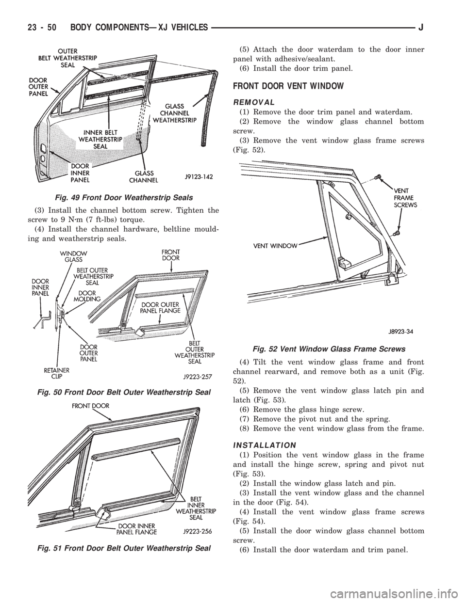
(2) Remove the window glass channel hardware,
beltline moulding and weatherstrip seals (Figs. 48
and 49).
(3) Remove the glass channel bottom screw.
(4) Remove the regulator-to-window glass screw,
bushing and retainer (Fig. 43).
(5) Lift the glass upward and out of the door.
INSTALLATION
(1) Position the glass in the door and install the
regulator-to-glass retainer, bushing and screw.
(2) Tighten the screw to 4 Nzm (36 in-lbs) torque.
Fig. 44 Manual Regulator InstallationÐUpper Rivets
Fig. 45 Manual Regulator InstallationÐLower Rivets
and Glass Retaining Screw
Fig. 46 Power Regulator InstallationÐUpper Rivets
Fig. 47 Power Regulator InstallationÐLower Rivets
Fig. 48 Front Door Beltline Moulding and Weatherstrip
Seals
JBODY COMPONENTSÐXJ VEHICLES 23 - 49
Page 1505 of 1784

(3) Install the channel bottom screw. Tighten the
screw to 9 Nzm (7 ft-lbs) torque.
(4) Install the channel hardware, beltline mould-
ing and weatherstrip seals.(5) Attach the door waterdam to the door inner
panel with adhesive/sealant.
(6) Install the door trim panel.
FRONT DOOR VENT WINDOW
REMOVAL
(1) Remove the door trim panel and waterdam.
(2) Remove the window glass channel bottom
screw.
(3) Remove the vent window glass frame screws
(Fig. 52).
(4) Tilt the vent window glass frame and front
channel rearward, and remove both as a unit (Fig.
52).
(5) Remove the vent window glass latch pin and
latch (Fig. 53).
(6) Remove the glass hinge screw.
(7) Remove the pivot nut and the spring.
(8) Remove the vent window glass from the frame.
INSTALLATION
(1) Position the vent window glass in the frame
and install the hinge screw, spring and pivot nut
(Fig. 53).
(2) Install the window glass latch and pin.
(3) Install the vent window glass and the channel
in the door (Fig. 54).
(4) Install the vent window glass frame screws
(Fig. 54).
(5) Install the door window glass channel bottom
screw.
(6) Install the door waterdam and trim panel.
Fig. 49 Front Door Weatherstrip Seals
Fig. 50 Front Door Belt Outer Weatherstrip Seal
Fig. 51 Front Door Belt Outer Weatherstrip Seal
Fig. 52 Vent Window Glass Frame Screws
23 - 50 BODY COMPONENTSÐXJ VEHICLESJ
Page 1506 of 1784
REAR DOOR WINDOW GLASS REGULATOR
REMOVAL
(1) Remove the door trim panel and waterdam.(2) Remove the window glass attaching screw,
bushing and retainer from the regulator (Fig. 55).
Support the glass.
Fig. 53 Vent Window Glass Disassembly/Assembly
Fig. 54 Vent Window Frame and Front Channel
Installation
Fig. 55 Regulator-To-Glass Screw
Removal/Installation
JBODY COMPONENTSÐXJ VEHICLES 23 - 51