Page 1478 of 1784

²ensure that 12 mm (1/2 in) excess overlay material
is allowed for wrapping around the door and fender
flanges; and
²cut the overlay to the approximate size with scis-
sors.
(2) Place the overlay on a clean, flat surface with
the paper liner facing upward.
(3) Bend the corner of the overlay toward the
woodgrain side and, with a flick of the finger, sepa-
rate the paper liner from the overlay.
OVERLAY APPLICATION
(1) Use a clean sponge and apply the wetting solu-
tion to the overlay adhesive and to the painted panel
surface.
(2) Position the adhesive side of the overlay on the
panel.
(3) Apply solution to the woodgrain side of the
overlay.
(4) For a complete, or a large section of overlay,
the following method should be used:
²position a squeegee at the center and slide it
across a short horizontal area of overlay;
²lift the right or left edge of the overlay, align it
with the panel. Slide the squeegee toward the lifted
edge with firm strokes;
²avoid stretching the overlay at its lifted edge;
²continue until all of the air bubbles and wetting
solution are removed from the underside of the over-
lay.
If a wrinkle is trapped in the overlay, stop im-
mediately. Lift the wrinkled area and re-align it
to remove the wrinkle. Do not lift the overlay if
only a few air bubbles exist.
(5) Notch the corner and curved edges of the over-
lay and trim the excess.
(6) Allow 12 mm (1/2 in) extra overlay to extend
beyond the edges.CAUTION: Use extreme care to avoid spilling iso-
propyl (rubbing) alcohol on the moulding or painted
surfaces. Wipe spills immediately.
(7) Wipe the adhesive side of edges with isopropyl
alcohol.
(8) Heat the overlay edges with a heat gun to
soften and make them more pliable.
(9) Fold the edges over onto the panel flange area
and press the overlay into place. Alternately heat
and press the edge until it is bonded to the flange
area.
(10) Carefully cut away the excess from panel the
openings with a knife.
(11) Inspect the overlay. Remove all the air and
moisture bubbles with a needle or pin.
(12) Install all the removed components and clean
the vehicle as necessary.
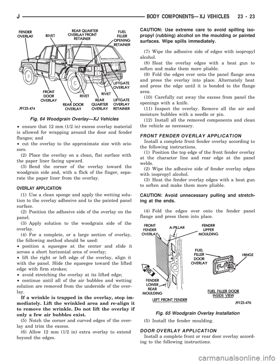
FRONT FENDER OVERLAY APPLICATION
Install a complete front fender overlay according to
the following instructions.
(1) Position the top edge of the front fender overlay
at the character line and rear edge at the panel
welds.
(2) Wipe the adhesive side of fender overlay edges
with isopropyl alcohol.
(3) Heat the fender overlay edges with a heat gun
to soften and make them more pliable.
CAUTION: Avoid unnecessary pulling and stretch-
ing at the ends.
(4) Fold the edges over onto the fender panel
flange and press them into place.
(5) Install the fender moulding.
DOOR OVERLAY APPLICATION
Install a complete front or rear door overlay accord-
ing to the following instructions.
Fig. 64 Woodgrain OverlayÐXJ Vehicles
Fig. 65 Woodgrain Overlay Installation
JBODY COMPONENTSÐXJ VEHICLES 23 - 23
Page 1479 of 1784

(1) Position the top edge of the door overlay at the
character line and the front edge at the panel welds.
(2) Wipe the adhesive side of the door overlay
edges with isopropyl alcohol.
(3) Heat the door overlay edges with a heat gun to
soften and make them more pliable.
CAUTION: Avoid unnecessary pulling and stretch-
ing at the ends.
(4) Fold edges over onto the door panel flange ar-
eas and press them into place.
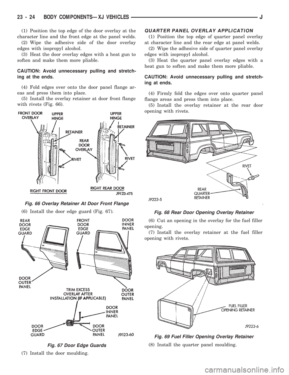
(5) Install the overlay retainer at door front flange
with rivets (Fig. 66).
(6) Install the door edge guard (Fig. 67).
(7) Install the door moulding.QUARTER PANEL OVERLAY APPLICATION
(1) Position the top edge of quarter panel overlay
at character line and the rear edge at panel welds.
(2) Wipe the adhesive side of quarter panel overlay
edges with isopropyl alcohol.
(3) Heat the quarter panel overlay edges with a
heat gun to soften and make them more pliable.
CAUTION: Avoid unnecessary pulling and stretch-
ing at ends.
(4) Firmly fold the edges over onto quarter panel
flange areas and press them into place.
(5) Install the overlay retainer at the rear door
opening with rivets.
(6) Cut an opening in the overlay for the fuel filler
opening.
(7) Install the overlay retainer at the fuel filler
opening with rivets.
(8) Install the quarter panel moulding.
Fig. 66 Overlay Retainer At Door Front Flange
Fig. 67 Door Edge Guards
Fig. 68 Rear Door Opening Overlay Retainer
Fig. 69 Fuel Filler Opening Overlay Retainer
23 - 24 BODY COMPONENTSÐXJ VEHICLESJ
Page 1489 of 1784

DOORS
INDEX
page page
Door Alignment AdjustmentÐMajor........... 47
Door Alignment AdjustmentÐMinor........... 46
Door Edge Guard/Edge Protector Strip........ 61
Door External Handle..................... 55
Door Hinge/Hinge Pin Replacement........... 58
Door Inside Latch Release and Lock Rods..... 57
Door Key Lock Cylinder................... 54
Door Latch............................. 56
Door Latch Adjustment.................... 55
Door Removal/Installation.................. 40
Door Restraint Replacement................ 47
Door Trim Panel......................... 35
Door Window Exterior Mouldings............. 61
Door Window Glass and Door Opening
Weatherstrip Seals...................... 62
Front Door Spacer BlocksÐTwo-Door Vehicles . . 60
Front Door Vent Window................... 50
Front Door Window Glass.................. 49Front Door Window Glass Regulator.......... 48
Liftgate Adjustment....................... 70
Liftgate Hinge........................... 67
Liftgate Latch/Key Lock Cylinder/Striker........ 68
Liftgate License Plate Lamp Housing.......... 72
Liftgate License Plate Screw Anchor and Bumper . 72
Liftgate Opening Weatherstrip Seal........... 70
Liftgate Removal/Installation................ 65
Liftgate Service InformationÐXJ Vehicles...... 65
Liftgate Support Rod Ball Stud Replacement.... 70
Liftgate Support Rod Cylinder............... 69
Liftgate Support Rod Cylinder Disposal........ 70
Liftgate Trim Panel....................... 66
Rear Door Fixed Window Glass............. 53
Rear Door Window Glass.................. 52
Rear Door Window Glass Regulator.......... 51
Service Information....................... 34
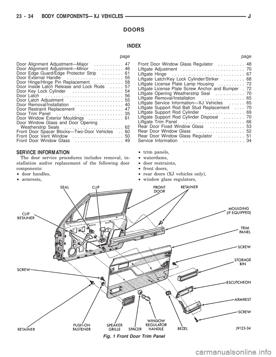
SERVICE INFORMATION
The door service procedures includes removal, in-
stallation and/or replacement of the following door
components:
²door handles,
²armrests,²trim panels,
²waterdams,
²door restraints,
²front doors,
²rear doors (XJ vehicles only),
²window glass regulators,
Fig. 1 Front Door Trim Panel
23 - 34 BODY COMPONENTSÐXJ VEHICLESJ
Page 1490 of 1784
²door vent and window glass,
²key lock cylinders,
²door half-hinges,
²liftgate (XJ vehicles only),
²liftgate hinges (XJ vehicles only),
²
liftgate gas support rod cylinders (XJ vehicles only),
²rocker panel seals, and
²mouldings/weatherstrip seals.
DOOR TRIM PANEL
SERVICE INFORMATION
All attached components can be removed from door
trim panels (Figs. 1 and 2).
REMOVAL
(1) Remove the door inside latch release handle
screws (Figs. 3 and 4).
(2) Move the door handle outward and disconnect
the handle-to-latch rods (Fig. 5). For vehicles
equipped with power door locks/windows, disconnect
the wire harness connector (Fig. 6).
(3) Remove the regulator handle (Fig. 7) or, if
equipped, power window switches and bezel.
(4) Remove the armrest lower screws.
(5) Pull armrest straight outward from panel and
remove the bezel.
Fig. 2 Rear Door Trim Panel
Fig. 3 Front Door Inside Latch Release Handle
Fig. 4 Rear Door Inside Latch Release Handle
JBODY COMPONENTSÐXJ VEHICLES 23 - 35
Page 1491 of 1784
Fig. 5 Door Inside Latch Release Rods
Fig. 6 Power Switch Wire Harness Connector
Fig. 7 Window Regulator Handles
Fig. 8 XJ Front Door Armrest Removal/Installation
Fig. 9 XJ Front Door Armrest Removal/Installation
Fig. 10 XJ Rear Door Armrest Removal/Installation
23 - 36 BODY COMPONENTSÐXJ VEHICLESJ
Page 1492 of 1784
(6) For XJ vehicles, remove the woodgrain mould-
ing from the door inner panel and the inner weath-
erstrip seal (Figs. 11 and 12).
(7) Remove the trim panel retainers from door in-
ner panel with a pry tool (Fig. 13).
(8) Remove the trim panel from door (Fig. 14).
Fig. 11 XJ Woodgrain MouldingÐFront Door
Fig. 12 XJ Woodgrain MouldingÐRear Door
Fig. 13 Detaching Trim Panel Serrated Retainers
Fig. 14 Front and Rear Door Trim Panels
JBODY COMPONENTSÐXJ VEHICLES 23 - 37
Page 1493 of 1784
(9) If necessary, remove the waterdam from the
door.
(10) If necessary, remove the storage bin panel and
speaker grille from the front door trim panel (Fig.
19).
Fig. 15 Front Door Waterdam
Fig. 16 Rear Door Waterdam
Fig. 17 Latch Release and Lock Rod Waterdam
Fig. 18 Power Switch Waterdam
Fig. 19 Storage Bin Panel and Speaker Grille
23 - 38 BODY COMPONENTSÐXJ VEHICLESJ
Page 1494 of 1784

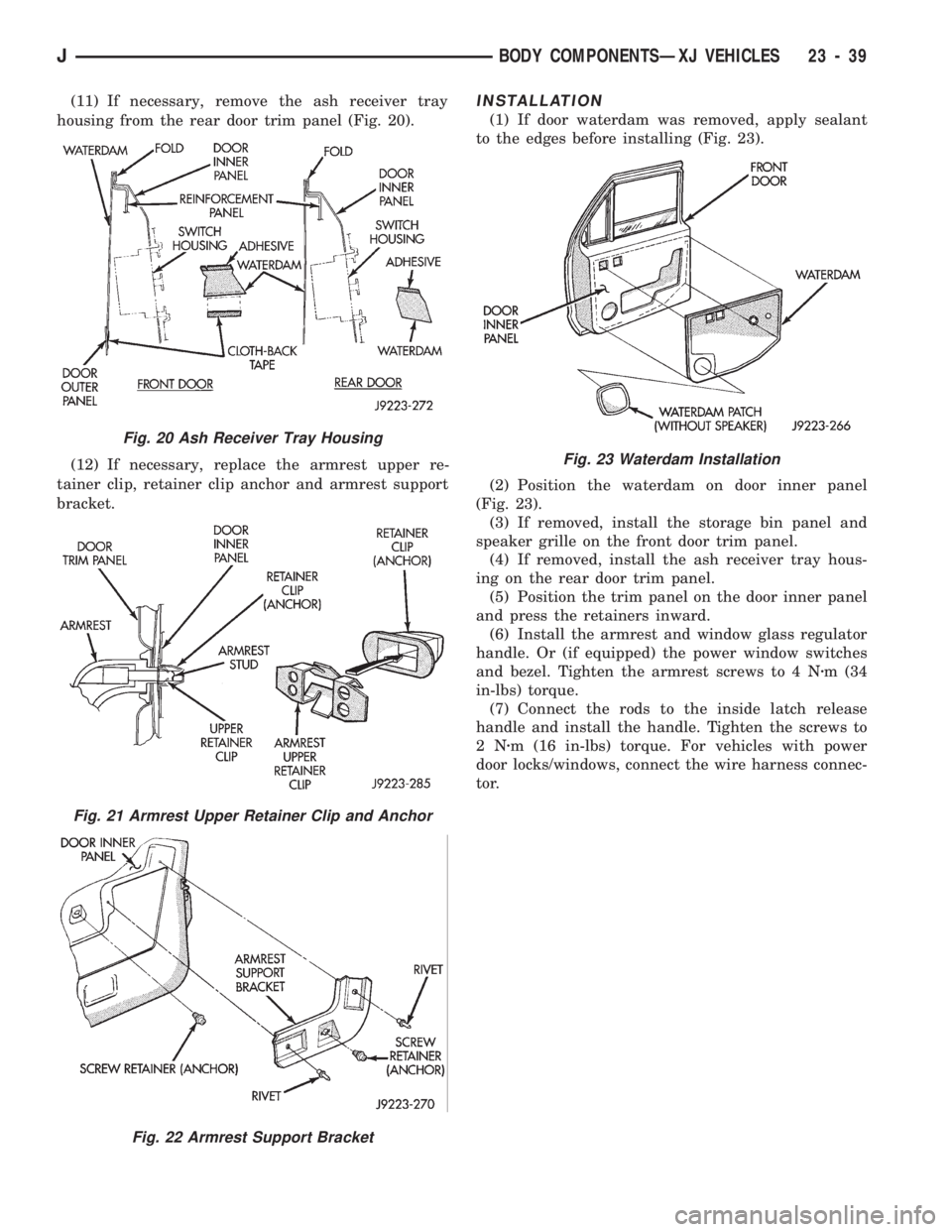
(11) If necessary, remove the ash receiver tray
housing from the rear door trim panel (Fig. 20).
(12) If necessary, replace the armrest upper re-
tainer clip, retainer clip anchor and armrest support
bracket.INSTALLATION
(1) If door waterdam was removed, apply sealant
to the edges before installing (Fig. 23).
(2) Position the waterdam on door inner panel
(Fig. 23).
(3) If removed, install the storage bin panel and
speaker grille on the front door trim panel.
(4) If removed, install the ash receiver tray hous-
ing on the rear door trim panel.
(5) Position the trim panel on the door inner panel
and press the retainers inward.
(6) Install the armrest and window glass regulator
handle. Or (if equipped) the power window switches
and bezel. Tighten the armrest screws to 4 Nzm (34
in-lbs) torque.
(7) Connect the rods to the inside latch release
handle and install the handle. Tighten the screws to
2Nzm (16 in-lbs) torque. For vehicles with power
door locks/windows, connect the wire harness connec-
tor.
Fig. 20 Ash Receiver Tray Housing
Fig. 21 Armrest Upper Retainer Clip and Anchor
Fig. 22 Armrest Support Bracket
Fig. 23 Waterdam Installation
JBODY COMPONENTSÐXJ VEHICLES 23 - 39