1994 JEEP CHEROKEE front
[x] Cancel search: frontPage 1589 of 1784
EXTERIOR COMPONENTS
INDEX
page page
Battery Tray........................... 140
Body Extension Panels and FasciasÐYJ
Renegade Vehicles..................... 147
Body Side Step Moulding................. 145
Body Stripes/Decals..................... 153
Cowl Grille and Screen................... 139
Cowl Weatherstrip Seal................... 139
Exterior Nameplates (Adhesive-Backed)....... 158
External Spare/Wheel Tire Carrier........... 172
Fender Flare........................... 144
Fender Inner Splash Shields............... 147
Fender Splash Aprons.................... 147
Fenders............................... 141
Fog LampÐYJ Renegade Vehicles.......... 150
Front Fascia and Skid PlateÐYJ Renegade
Vehicles............................. 148
Front Fender Extension PanelÐYJ Renegade
Vehicles............................. 149
Fuel Filler Protector/Nozzle................ 158
Half Metal Door Mirror (External)............ 158
Hard Top Liftgate Glass.................. 162
Hard Top Repair........................ 165
Hard Top Roof Vent..................... 165
Hard Top Service....................... 164
Hard Top Service Information.............. 164Hood................................. 137
Hood Alignment......................... 138
Hood Insulator Panel..................... 138
Hood Safety Latch....................... 139
Liftgate Glass Weatherstrip Seal Replacement . . 163
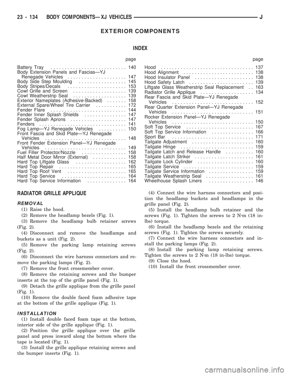
Radiator Grille Applique................... 134
Rear Fascia and Skid PlateÐYJ Renegade
Vehicles............................. 152
Rear Quarter Extension PanelÐYJ Renegade
Vehicles............................. 151
Rocker Extension PanelÐYJ Renegade
Vehicles............................. 150
Soft Top Service........................ 167
Soft Top Service Information............... 166
Sport Bar............................. 171
Tailgate Adjustment...................... 160
Tailgate Hinge.......................... 159
Tailgate Latch and Release Handle.......... 160
Tailgate Latch Striker..................... 161
Tailgate Lock Cylinder.................... 160
Tailgate Service......................... 159
Tailgate Service Information................ 159
Tailgate Weatherstrip Seal................. 161
Wheelhouse Splash Liners................ 146
RADIATOR GRILLE APPLIQUE
REMOVAL
(1) Raise the hood.
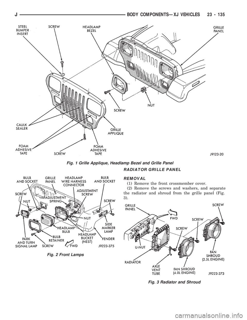
(2) Remove the headlamp bezels (Fig. 1).
(3) Remove the headlamp bulb retainer screws
(Fig. 2).
(4) Disconnect and remove the headlamps and
buckets as a unit (Fig. 2).
(5) Remove the parking lamp retaining screws
(Fig. 2).
(6) Disconnect the wire harness connectors and re-
move the parking lamps (Fig. 2).
(7) Remove the front crossmember cover.
(8) Remove the retaining screws and the bumper
inserts at the top of the grille panel (Fig. 1).
(9) Detach the grille applique from the grille panel
(Fig. 1).
(10) Remove the double faced foam adhesive tape
at the bottom of the grille applique (Fig. 1).
INSTALLATION
(1) Install double faced foam tape at the bottom,
interior side of the grille applique (Fig. 1).
(2) Position the grille applique over the grille
panel and press inward along the bottom where the
tape is located (Fig. 1).
(3) Install the grille applique retaining screws and
the bumper inserts (Fig. 1).(4) Connect the wire harness connectors and posi-
tion the headlamp buckets and headlamps in the
grille panel (Fig. 2).
(5) Install the headlamp bulb retainer and the
screws (Fig. 1). Tighten the screws to 2 Nzm (18 in-
lbs) torque.
(6) Install the headlamp bezels and the retaining
screws (Fig. 1). Tighten the screws securely.
(7) Connect the wire harness connectors and in-
stall the parking lamps (Fig. 2).
(8) Install the parking lamp retaining screws.
Tighten the screws to 2 Nzm (18 in-lbs) torque.
(9) Close the hood.
(10) Install the front crossmember cover.
23 - 134 BODY COMPONENTSÐXJ VEHICLESJ
Page 1590 of 1784
RADIATOR GRILLE PANEL
REMOVAL
(1) Remove the front crossmember cover.
(2) Remove the screws and washers, and separate
the radiator and shroud from the grille panel (Fig.
3).
Fig. 1 Grille Applique, Headlamp Bezel and Grille Panel
Fig. 2 Front Lamps
Fig. 3 Radiator and Shroud
JBODY COMPONENTSÐXJ VEHICLES 23 - 135
Page 1591 of 1784
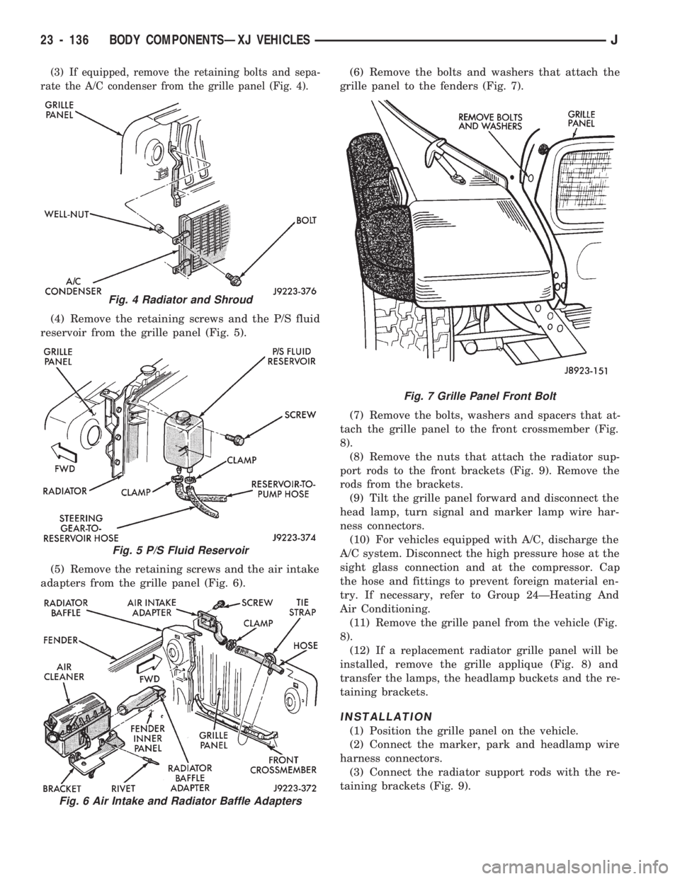
(3) If equipped, remove the retaining bolts and sepa-
rate the A/C condenser from the grille panel (Fig. 4).
(4) Remove the retaining screws and the P/S fluid
reservoir from the grille panel (Fig. 5).
(5) Remove the retaining screws and the air intake
adapters from the grille panel (Fig. 6).(6) Remove the bolts and washers that attach the
grille panel to the fenders (Fig. 7).
(7) Remove the bolts, washers and spacers that at-
tach the grille panel to the front crossmember (Fig.
8).
(8) Remove the nuts that attach the radiator sup-
port rods to the front brackets (Fig. 9). Remove the
rods from the brackets.
(9) Tilt the grille panel forward and disconnect the
head lamp, turn signal and marker lamp wire har-
ness connectors.
(10) For vehicles equipped with A/C, discharge the
A/C system. Disconnect the high pressure hose at the
sight glass connection and at the compressor. Cap
the hose and fittings to prevent foreign material en-
try. If necessary, refer to Group 24ÐHeating And
Air Conditioning.
(11) Remove the grille panel from the vehicle (Fig.
8).
(12) If a replacement radiator grille panel will be
installed, remove the grille applique (Fig. 8) and
transfer the lamps, the headlamp buckets and the re-
taining brackets.
INSTALLATION
(1) Position the grille panel on the vehicle.
(2) Connect the marker, park and headlamp wire
harness connectors.
(3) Connect the radiator support rods with the re-
taining brackets (Fig. 9).
Fig. 4 Radiator and Shroud
Fig. 5 P/S Fluid Reservoir
Fig. 6 Air Intake and Radiator Baffle Adapters
Fig. 7 Grille Panel Front Bolt
23 - 136 BODY COMPONENTSÐXJ VEHICLESJ
Page 1592 of 1784
(4) Attach the grille panel to the front crossmember.
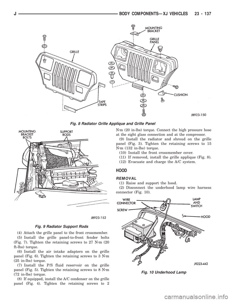
(5) Install the grille panel-to-front fender bolts
(Fig. 7). Tighten the retaining screws to 27 Nzm (20
ft-lbs) torque.
(6) Install the air intake adapters on the grille
panel (Fig. 6). Tighten the retaining screws to 3 Nzm
(25 in-lbs) torque.
(7) Install the P/S fluid reservoir on the grille
panel (Fig. 5). Tighten the retaining screws to 8 Nzm
(72 in-lbs) torque.
(8) If equipped, install the A/C condenser on the grille
panel (Fig. 4). Tighten the retaining screws to 2Nzm (20 in-lbs) torque. Connect the high pressure hose
at the sight glass connection and at the compressor.
(9) Install the radiator and shroud on the grille
panel (Fig. 3). Tighten the retaining screws to 15
Nzm (132 in-lbs) torque.
(10) Install the front crossmember cover.
(11) If removed, install the grille applique (Fig. 8).
(12) Evacuate and charge the A/C system.
HOOD
REMOVAL
(1) Raise and support the hood.
(2) Disconnect the underhood lamp wire harness
connector (Fig. 10).
Fig. 8 Radiator Grille Applique and Grille Panel
Fig. 9 Radiator Support Rods
Fig. 10 Underhood Lamp
JBODY COMPONENTSÐXJ VEHICLES 23 - 137
Page 1596 of 1784
FENDERS
SERVICE INFORMATION
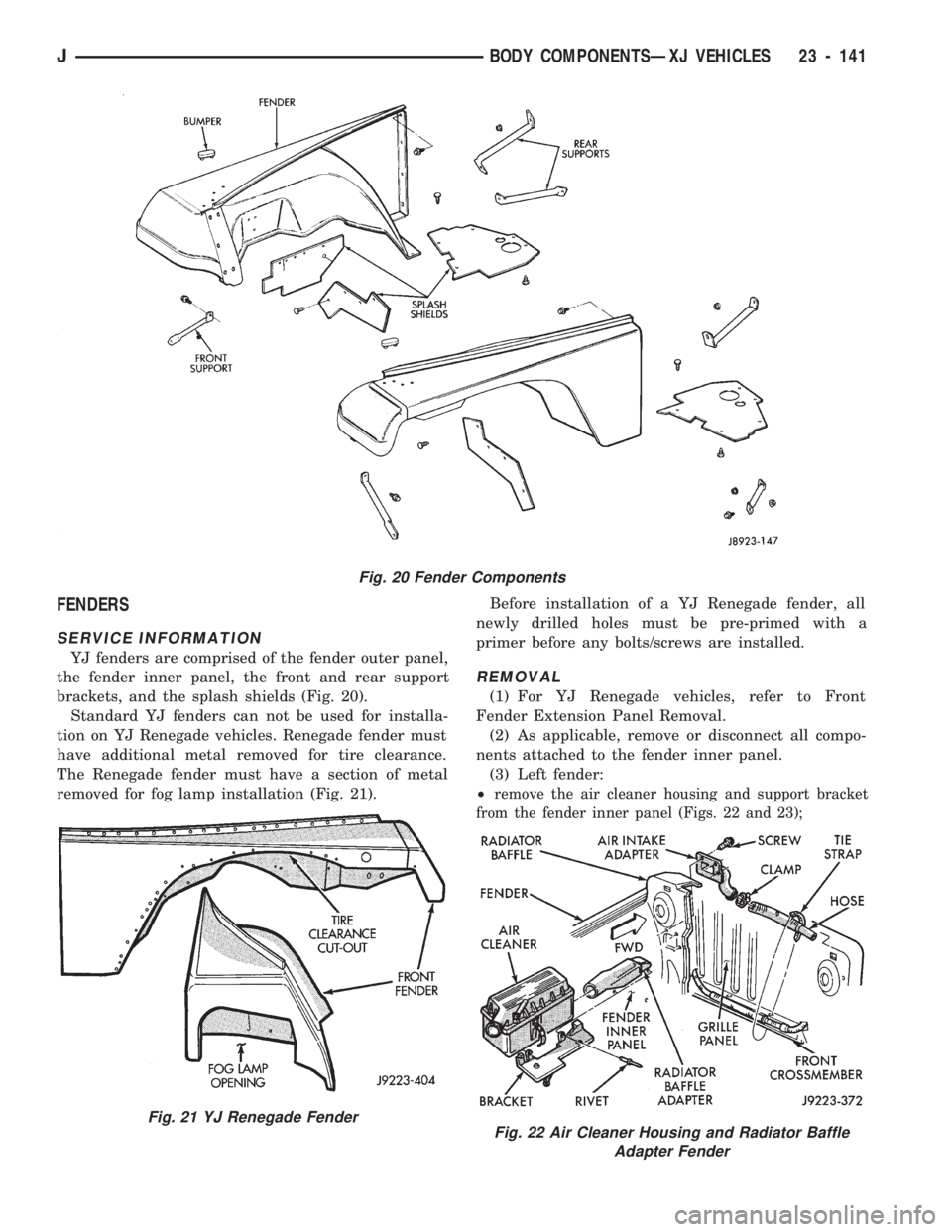
YJ fenders are comprised of the fender outer panel,
the fender inner panel, the front and rear support
brackets, and the splash shields (Fig. 20).
Standard YJ fenders can not be used for installa-
tion on YJ Renegade vehicles. Renegade fender must
have additional metal removed for tire clearance.
The Renegade fender must have a section of metal
removed for fog lamp installation (Fig. 21).Before installation of a YJ Renegade fender, all
newly drilled holes must be pre-primed with a
primer before any bolts/screws are installed.
REMOVAL
(1) For YJ Renegade vehicles, refer to Front
Fender Extension Panel Removal.
(2) As applicable, remove or disconnect all compo-
nents attached to the fender inner panel.
(3) Left fender:
²
remove the air cleaner housing and support bracket
from the fender inner panel (Figs. 22 and 23);
Fig. 20 Fender Components
Fig. 21 YJ Renegade FenderFig. 22 Air Cleaner Housing and Radiator Baffle
Adapter Fender
JBODY COMPONENTSÐXJ VEHICLES 23 - 141
Page 1598 of 1784
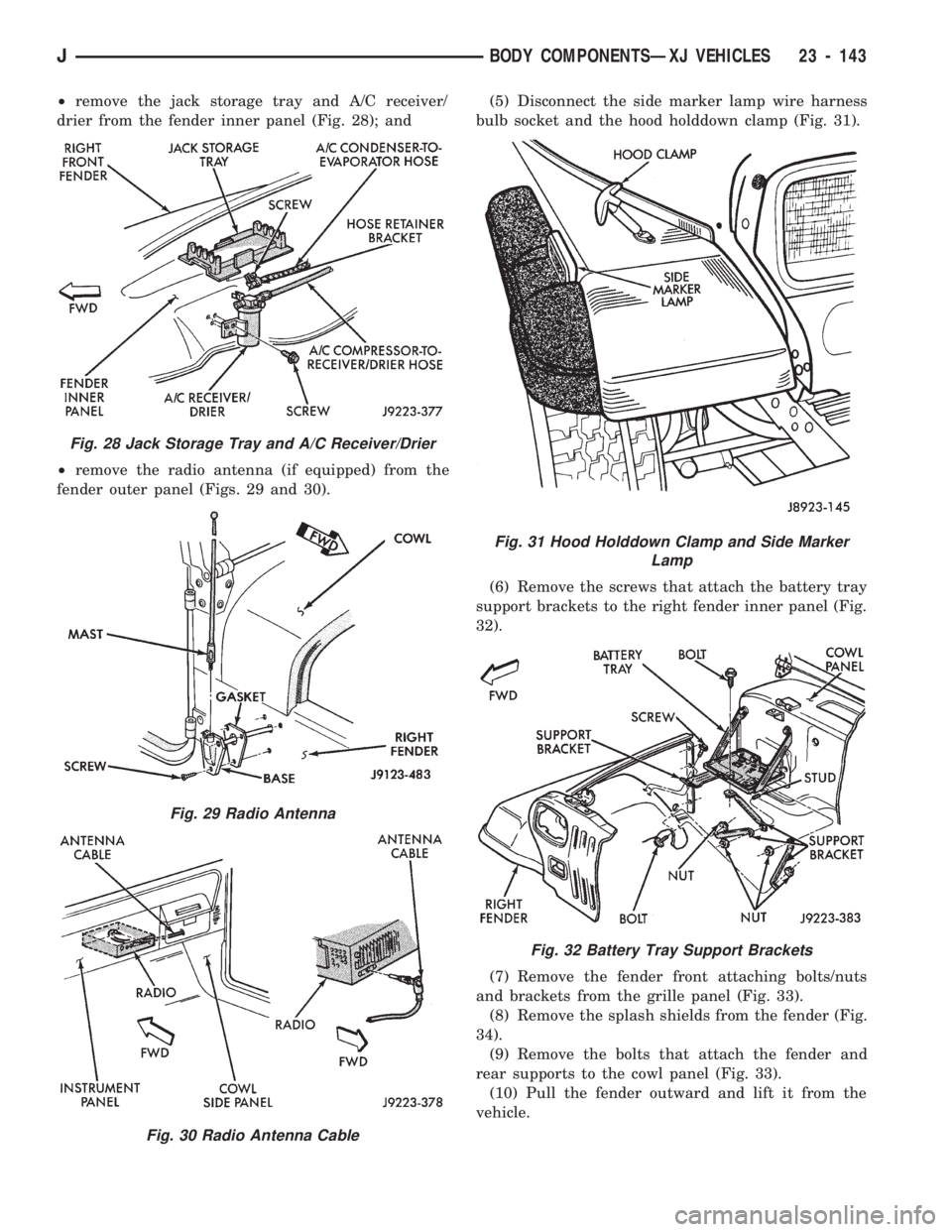
²remove the jack storage tray and A/C receiver/
drier from the fender inner panel (Fig. 28); and
²remove the radio antenna (if equipped) from the
fender outer panel (Figs. 29 and 30).(5) Disconnect the side marker lamp wire harness
bulb socket and the hood holddown clamp (Fig. 31).
(6) Remove the screws that attach the battery tray
support brackets to the right fender inner panel (Fig.
32).
(7) Remove the fender front attaching bolts/nuts
and brackets from the grille panel (Fig. 33).
(8) Remove the splash shields from the fender (Fig.
34).
(9) Remove the bolts that attach the fender and
rear supports to the cowl panel (Fig. 33).
(10) Pull the fender outward and lift it from the
vehicle.
Fig. 28 Jack Storage Tray and A/C Receiver/Drier
Fig. 29 Radio Antenna
Fig. 30 Radio Antenna Cable
Fig. 31 Hood Holddown Clamp and Side Marker
Lamp
Fig. 32 Battery Tray Support Brackets
JBODY COMPONENTSÐXJ VEHICLES 23 - 143
Page 1599 of 1784
INSTALLATION
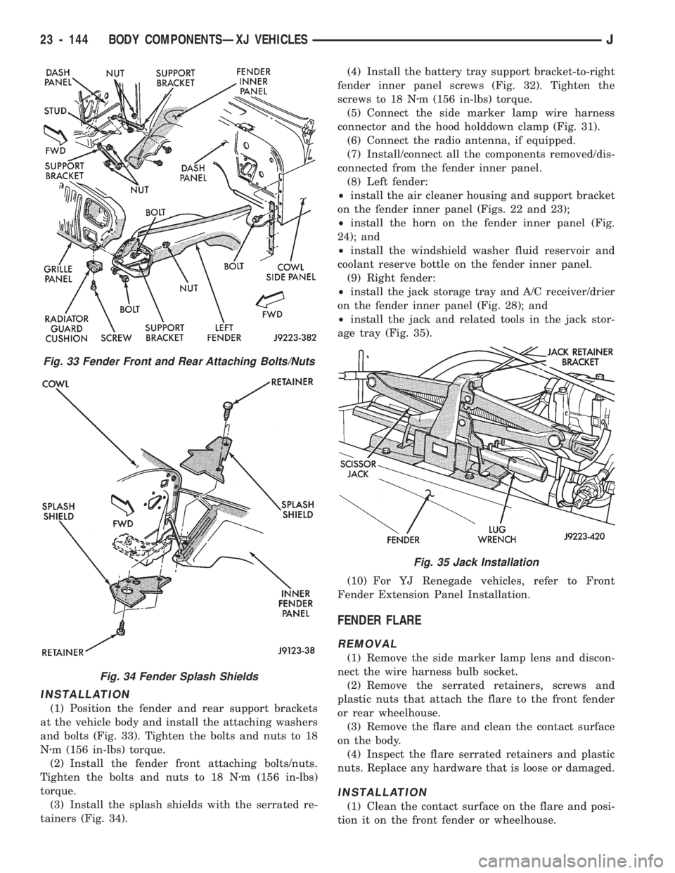
(1) Position the fender and rear support brackets
at the vehicle body and install the attaching washers
and bolts (Fig. 33). Tighten the bolts and nuts to 18
Nzm (156 in-lbs) torque.
(2) Install the fender front attaching bolts/nuts.
Tighten the bolts and nuts to 18 Nzm (156 in-lbs)
torque.
(3) Install the splash shields with the serrated re-
tainers (Fig. 34).(4) Install the battery tray support bracket-to-right
fender inner panel screws (Fig. 32). Tighten the
screws to 18 Nzm (156 in-lbs) torque.
(5) Connect the side marker lamp wire harness
connector and the hood holddown clamp (Fig. 31).
(6) Connect the radio antenna, if equipped.
(7) Install/connect all the components removed/dis-
connected from the fender inner panel.
(8) Left fender:
²install the air cleaner housing and support bracket
on the fender inner panel (Figs. 22 and 23);
²install the horn on the fender inner panel (Fig.
24); and
²install the windshield washer fluid reservoir and
coolant reserve bottle on the fender inner panel.
(9) Right fender:
²install the jack storage tray and A/C receiver/drier
on the fender inner panel (Fig. 28); and
²install the jack and related tools in the jack stor-
age tray (Fig. 35).
(10) For YJ Renegade vehicles, refer to Front
Fender Extension Panel Installation.
FENDER FLARE
REMOVAL
(1) Remove the side marker lamp lens and discon-
nect the wire harness bulb socket.
(2) Remove the serrated retainers, screws and
plastic nuts that attach the flare to the front fender
or rear wheelhouse.
(3) Remove the flare and clean the contact surface
on the body.
(4) Inspect the flare serrated retainers and plastic
nuts. Replace any hardware that is loose or damaged.
INSTALLATION
(1) Clean the contact surface on the flare and posi-
tion it on the front fender or wheelhouse.
Fig. 33 Fender Front and Rear Attaching Bolts/Nuts
Fig. 34 Fender Splash Shields
Fig. 35 Jack Installation
23 - 144 BODY COMPONENTSÐXJ VEHICLESJ
Page 1600 of 1784
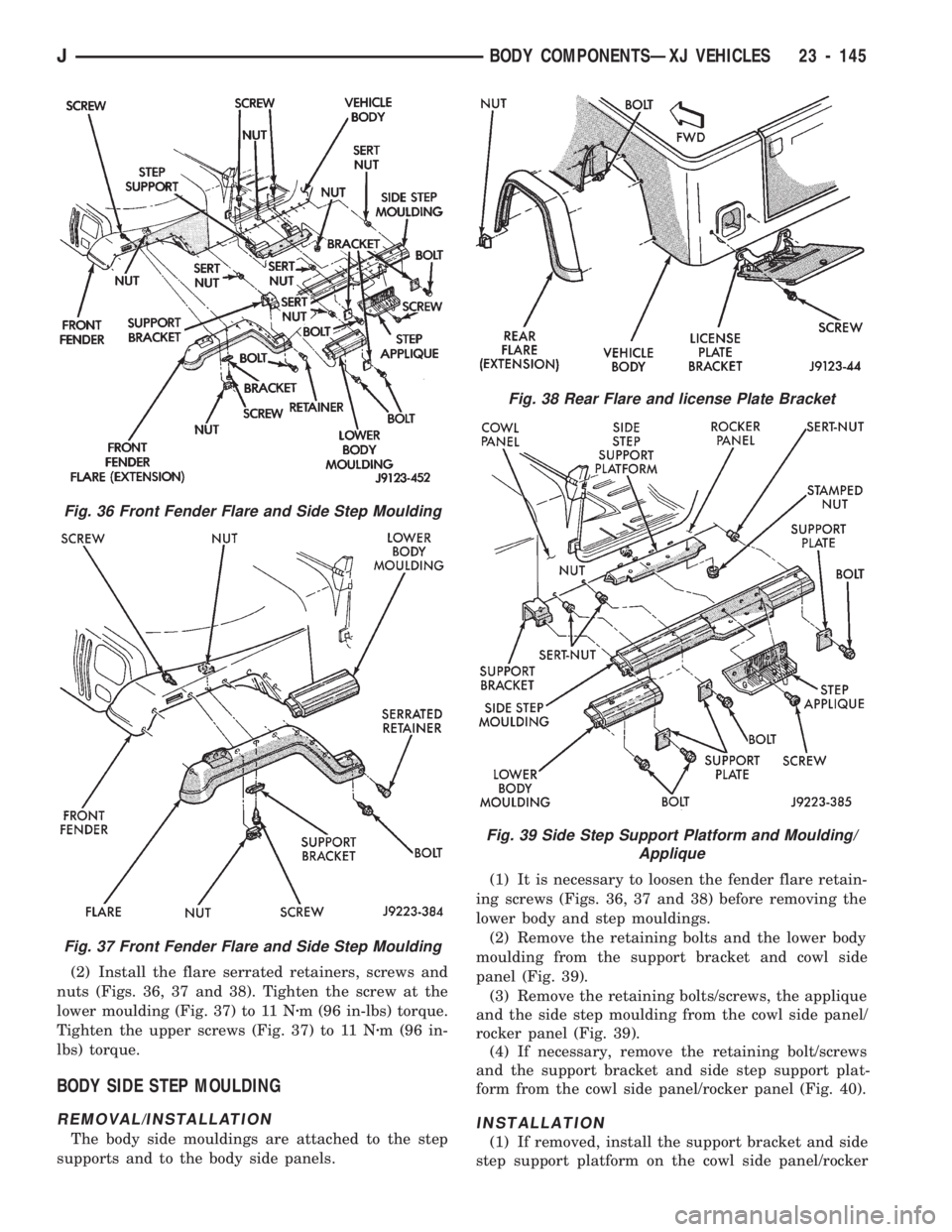
(2) Install the flare serrated retainers, screws and
nuts (Figs. 36, 37 and 38). Tighten the screw at the
lower moulding (Fig. 37) to 11 Nzm (96 in-lbs) torque.
Tighten the upper screws (Fig. 37) to 11 Nzm (96 in-
lbs) torque.
BODY SIDE STEP MOULDING
REMOVAL/INSTALLATION
The body side mouldings are attached to the step
supports and to the body side panels.(1) It is necessary to loosen the fender flare retain-
ing screws (Figs. 36, 37 and 38) before removing the
lower body and step mouldings.
(2) Remove the retaining bolts and the lower body
moulding from the support bracket and cowl side
panel (Fig. 39).
(3) Remove the retaining bolts/screws, the applique
and the side step moulding from the cowl side panel/
rocker panel (Fig. 39).
(4) If necessary, remove the retaining bolt/screws
and the support bracket and side step support plat-
form from the cowl side panel/rocker panel (Fig. 40).
INSTALLATION
(1) If removed, install the support bracket and side
step support platform on the cowl side panel/rocker
Fig. 38 Rear Flare and license Plate Bracket
Fig. 39 Side Step Support Platform and Moulding/
Applique
Fig. 36 Front Fender Flare and Side Step Moulding
Fig. 37 Front Fender Flare and Side Step Moulding
JBODY COMPONENTSÐXJ VEHICLES 23 - 145