1994 JEEP CHEROKEE front
[x] Cancel search: frontPage 1681 of 1784
²Used belt tensionÐ623-712 N (140-160 lb-f).
(5) Remove the tape or plastic plugs from all the
suction and discharge openings and install the ser-
vice valves on the compressor.
(6) Connect the clutch lead wire.
(7) Connect negative cable to battery.
(8) Evacuate, charge and test the system for leaks.
MAGNETIC CLUTCH
The magnetic clutch consists of a stationary elec-
tro-magnetic coil and a rotating pulley and plate as-
sembly.
The electromagnetic coil is retained on the com-
pressor with a snap ring and is dimpled to maintain
its position.The pulley and plate assembly are mounted on the
compressor shaft.
When the compressor is not in operation, the pul-
ley free wheels on the clutch hub bearing. When the
coil is energized the plate is magnetically engaged
with the pulley and turns the compressor shaft.
REMOVAL
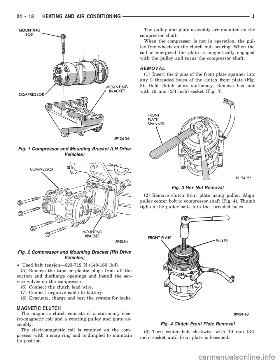
(1) Insert the 2 pins of the front plate spanner into
any 2 threaded holes of the clutch front plate (Fig.
3). Hold clutch plate stationary. Remove hex nut
with 19 mm (3/4 inch) socket (Fig. 3).
(2) Remove clutch front plate using puller. Align
puller center bolt to compressor shaft (Fig. 4). Thumb
tighten the puller bolts into the threaded holes.
(3) Turn center bolt clockwise with 19 mm (3/4
inch) socket until front plate is loosened.
Fig. 1 Compressor and Mounting Bracket (LH Drive
Vehicles)
Fig. 2 Compressor and Mounting Bracket (RH Drive
Vehicles)
Fig. 3 Hex Nut Removal
Fig. 4 Clutch Front Plate Removal
24 - 18 HEATING AND AIR CONDITIONINGJ
Page 1682 of 1784
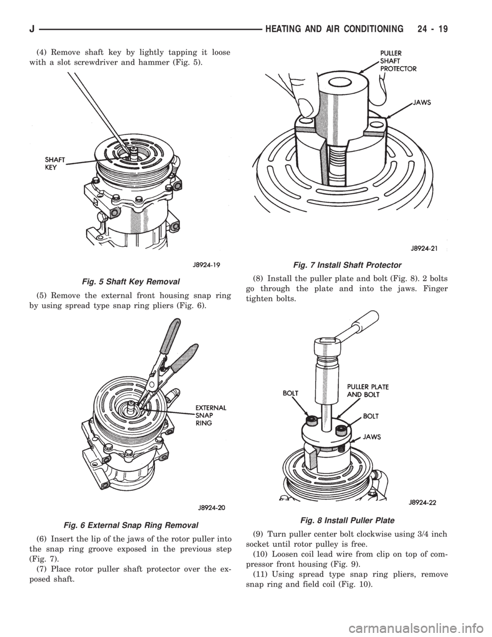
(4) Remove shaft key by lightly tapping it loose
with a slot screwdriver and hammer (Fig. 5).
(5) Remove the external front housing snap ring
by using spread type snap ring pliers (Fig. 6).
(6) Insert the lip of the jaws of the rotor puller into
the snap ring groove exposed in the previous step
(Fig. 7).
(7) Place rotor puller shaft protector over the ex-
posed shaft.(8) Install the puller plate and bolt (Fig. 8). 2 bolts
go through the plate and into the jaws. Finger
tighten bolts.
(9) Turn puller center bolt clockwise using 3/4 inch
socket until rotor pulley is free.
(10) Loosen coil lead wire from clip on top of com-
pressor front housing (Fig. 9).
(11) Using spread type snap ring pliers, remove
snap ring and field coil (Fig. 10).
Fig. 5 Shaft Key Removal
Fig. 6 External Snap Ring Removal
Fig. 7 Install Shaft Protector
Fig. 8 Install Puller Plate
JHEATING AND AIR CONDITIONING 24 - 19
Page 1683 of 1784
INSTALLATION
(1) Install the field coil with the snap ring.
(2) Place coil lead wire under clip on top of com-
pressor front housing and tighten the retaining
screw.
(3) Support the compressor on the 4 mounting ears
at the compressor rear. If a vise is being used, clamp
only on the mounting ears. Never clamp on the com-
pressor body.
(4) Align rotor assembly squarely on the front
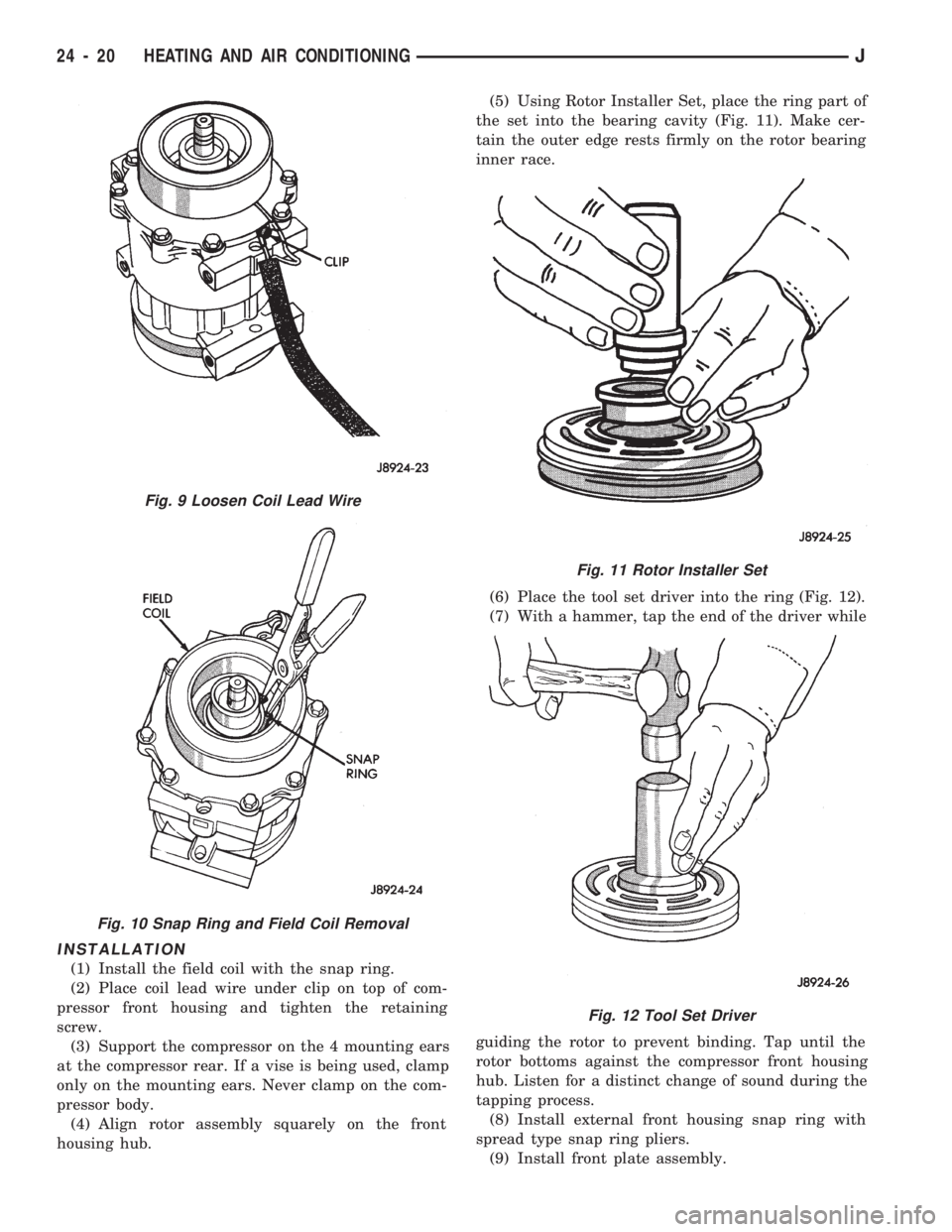
housing hub.(5) Using Rotor Installer Set, place the ring part of
the set into the bearing cavity (Fig. 11). Make cer-
tain the outer edge rests firmly on the rotor bearing
inner race.
(6) Place the tool set driver into the ring (Fig. 12).
(7) With a hammer, tap the end of the driver while
guiding the rotor to prevent binding. Tap until the
rotor bottoms against the compressor front housing
hub. Listen for a distinct change of sound during the
tapping process.
(8) Install external front housing snap ring with
spread type snap ring pliers.
(9) Install front plate assembly.
Fig. 9 Loosen Coil Lead Wire
Fig. 10 Snap Ring and Field Coil Removal
Fig. 11 Rotor Installer Set
Fig. 12 Tool Set Driver
24 - 20 HEATING AND AIR CONDITIONINGJ
Page 1684 of 1784
²Check that original clutch shims are in place on
compressor shaft.
²Replace compressor shaft key.
²Align front plate keyway to compressor shaft key.
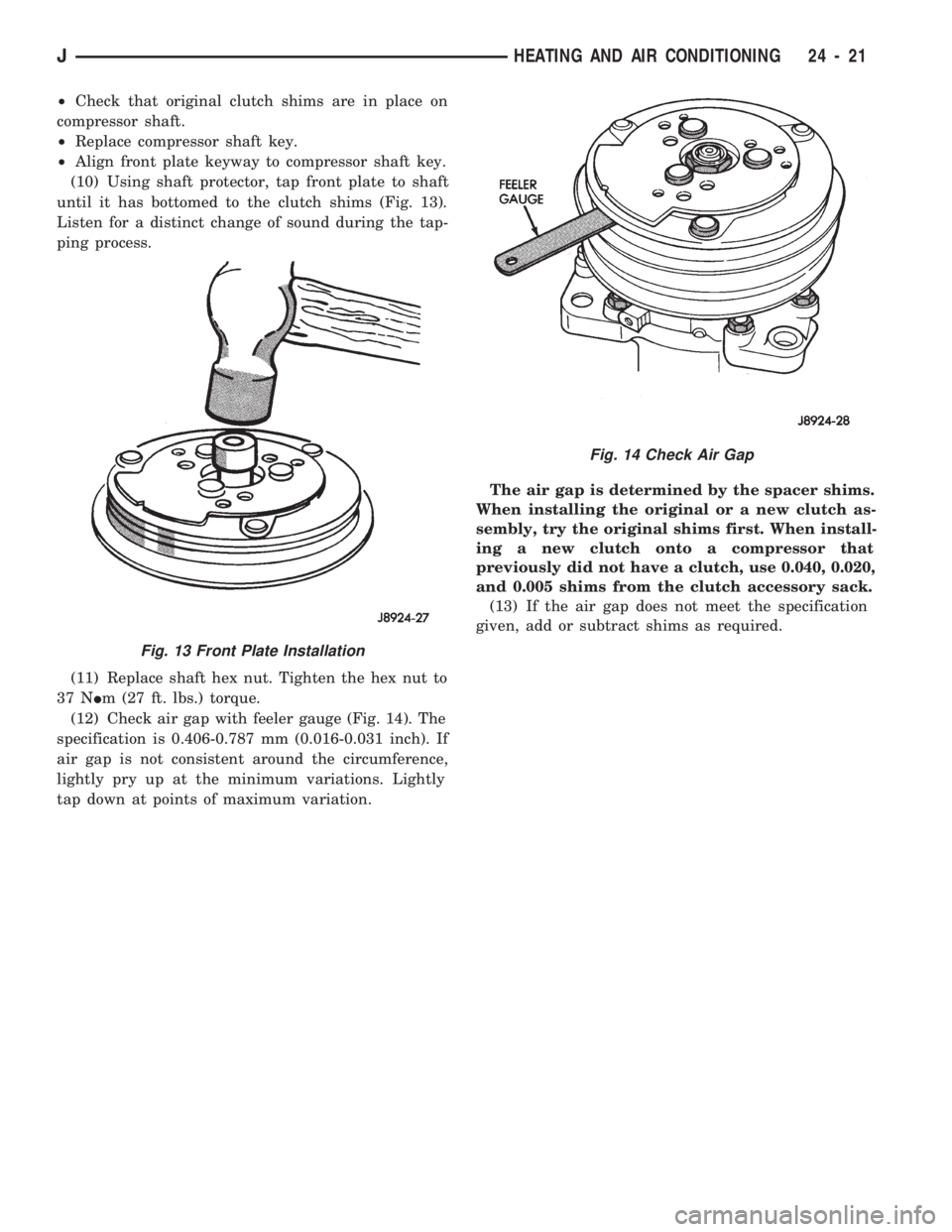
(10) Using shaft protector, tap front plate to shaft
until it has bottomed to the clutch shims (Fig. 13).
Listen for a distinct change of sound during the tap-
ping process.
(11) Replace shaft hex nut. Tighten the hex nut to
37 NIm (27 ft. lbs.) torque.
(12) Check air gap with feeler gauge (Fig. 14). The
specification is 0.406-0.787 mm (0.016-0.031 inch). If
air gap is not consistent around the circumference,
lightly pry up at the minimum variations. Lightly
tap down at points of maximum variation.The air gap is determined by the spacer shims.
When installing the original or a new clutch as-
sembly, try the original shims first. When install-
ing a new clutch onto a compressor that
previously did not have a clutch, use 0.040, 0.020,
and 0.005 shims from the clutch accessory sack.
(13) If the air gap does not meet the specification
given, add or subtract shims as required.
Fig. 13 Front Plate Installation
Fig. 14 Check Air Gap
JHEATING AND AIR CONDITIONING 24 - 21
Page 1710 of 1784
AIR CONDITIONING
CONTENTS
page page
AIR CONDITIONING EQUIPMENT........... 4
AIR CONDITIONING PERFORMANCE TESTS . . 5
GENERAL INFORMATION.................. 1
REFRIGERANT LEAK TESTING, DISCHARGING,
EVACUATING AND CHARGING............ 8REFRIGERANT OIL....................... 9
SERVICE PRECAUTIONS.................. 3
WARNINGS AND CAUTIONS FOR R134A
SYSTEM.............................. 3
GENERAL INFORMATION
A/C COMPONENTS
COMPRESSORÐThe SD-709 Compressor is used
on all models. The compressor compresses the low-
pressure refrigerant vapor from the evaporator into a
high pressure, high temperature vapor. The compres-
sor is serviced as an assembly only.
CLUTCH PULLEY AND COILÐThey are
mounted on the compressor and providing a way to
drive the compressor. The compressor clutch and coil
are the only serviced parts on the SD-709 compres-
sor. When the compressor is not in operation, the
pulley free wheels on the clutch hub bearing. When
the coil is energized the clutch plate is magnetically
engaged with the pulley and turns the compressor
shaft.
CONDENSERÐThe condenser is located in front
of the engine radiator. Its function is to cool the hot
high pressure refrigerant gas. This causes it to con-
dense into high pressure liquid refrigerant.
FILTER-DRIERÐThe drier is used to remove con-
taminates and traces of moisture from the refriger-
ant system.
SIGHT-GLASSÐThe sight glass is located on top
of the filter drier. It is used as a diagnostic tool to ob-
serve refrigerant flow.
LOW-PRESSURE HIGH-PRESSURE CUT-OFF
SWITCHÐThe switch is located on the filter drier
and is wired in series with compressor clutch. When
the pressure drops down to 193 kPa (28 psi) the
switch interrupts the power to the compressor clutch.
When the pressure increases above 3100 to 3375 kPa
(450 to 490 psi) the switch interrupts the power to
the compressor clutch.
HIGH PRESSURE RELIEF VALVEÐThe valve
is located on the filter drier. The valve is used to pre-
vent excessive pressure up build of 3445 to 4135
kPag (500 to 600 psi) and above. This will prevent
damage to the compressor and other system compo-
nents.EXPANSION VALVEÐThe expansion valve is lo-
cated in the engine compartment on XJ vehicles. On
YJ vehicles it is located behind the A/C housing. Its
function is to meter refrigerant into the evaporator in
accordance with cooling requirements.
EVAPORATOR COILÐThe coil is located in the
A/C housing. Its function is to remove heat and de-
humidify the air before it enters the vehicle.
FIN SENSING CYCLING CLUTCH SWITCHÐ
The switch is attached to the evaporator coil. This
switch prevents condensate water on the evaporator
coil from freezing. It does this by cycling the com-
pressor clutch on and off. This switch is used onXJ
only
THERMOSTATÐThe thermostat is located in the
evaporator housing. Its function is to cycle the com-
pressor clutch to control temperature. The thermo-
stat is used on theYJonly.
REFRIGERANT LINESÐThe lines are used to
carry the refrigerant between the various system
components.
SERVICE PORTSÐThe high pressure service
port is located on the discharge line near the com-
pressor. The low pressure service port is located on
the suction line near the compressor. The compressor
no longer uses service valves.
After servicing the refrigerant system, always in-
stall service port caps.
REFRIGERANT
The vehicles use a new type of refrigerant called
R-134a. It is a non-toxic, non-flammable, clear color-
less liquified gas.
R-134a refrigerant is not compatible with R-12 re-
frigerant in an air conditioning system. A small
amount of R-12 in a R-134a system will cause com-
pressor failure, refrigerant oil sludge or poor A/C per-
formance.
JAIR CONDITIONING1
Page 1723 of 1784
CAUTION: The fuel filler cap must be removed prior
to disconnecting any fuel system component.
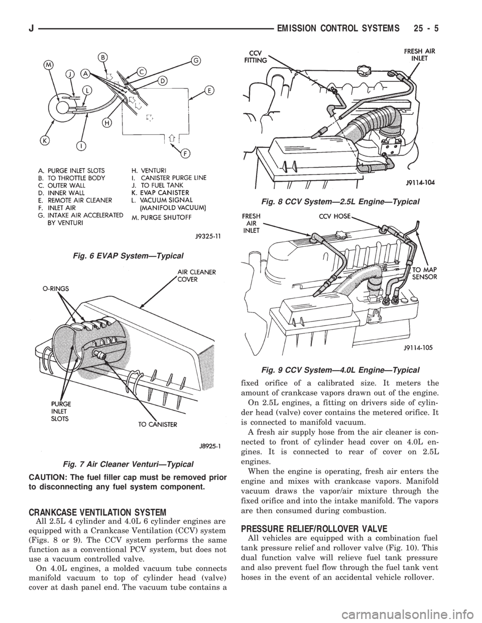
CRANKCASE VENTILATION SYSTEM
All 2.5L 4 cylinder and 4.0L 6 cylinder engines are
equipped with a Crankcase Ventilation (CCV) system
(Figs. 8 or 9). The CCV system performs the same
function as a conventional PCV system, but does not
use a vacuum controlled valve.
On 4.0L engines, a molded vacuum tube connects
manifold vacuum to top of cylinder head (valve)
cover at dash panel end. The vacuum tube contains afixed orifice of a calibrated size. It meters the
amount of crankcase vapors drawn out of the engine.
On 2.5L engines, a fitting on drivers side of cylin-
der head (valve) cover contains the metered orifice. It
is connected to manifold vacuum.
A fresh air supply hose from the air cleaner is con-
nected to front of cylinder head cover on 4.0L en-
gines. It is connected to rear of cover on 2.5L
engines.
When the engine is operating, fresh air enters the
engine and mixes with crankcase vapors. Manifold
vacuum draws the vapor/air mixture through the
fixed orifice and into the intake manifold. The vapors
are then consumed during combustion.
PRESSURE RELIEF/ROLLOVER VALVE
All vehicles are equipped with a combination fuel
tank pressure relief and rollover valve (Fig. 10). This
dual function valve will relieve fuel tank pressure
and also prevent fuel flow through the fuel tank vent
hoses in the event of an accidental vehicle rollover.
Fig. 6 EVAP SystemÐTypical
Fig. 7 Air Cleaner VenturiÐTypical
Fig. 8 CCV SystemÐ2.5L EngineÐTypical
Fig. 9 CCV SystemÐ4.0L EngineÐTypical
JEMISSION CONTROL SYSTEMS 25 - 5
Page 1731 of 1784
NOTE: Groups with the suffix ª-Sº are supplements to
the original service manual publication.
GROUP TAB LOCATOR PAGE
INIntroduction
0Lubrication and Maintenance
2Front Suspension and Axle
3Rear Suspension and Axles
5Brakes
6Clutch
7Cooling System
8Electrical
9Engines
11Exhaust System and Intake Manifold
13Frame and Bumpers
14Fuel System
16Propeller Shafts
19Steering
21Transmissions and Transfer Cases
22Wheels and Tires
23Body Components
24Heating and Air Conditioning
24-SAir Conditioning
25Emission Control Systems
Index
Index Supplement
Service Manual Comment Forms (Rear of Manual)
Page 1735 of 1784
INTRODUCTION
CONTENTS
page page
DESIGNATIONS, LABELS/PLATES, CODES
AND DIMENSIONS..................... 1SPECIFICATIONS........................ 8
DESIGNATIONS, LABELS/PLATES, CODES AND DIMENSIONS
INDEX
page page
Engine and Transmission/Transfer Case Identification.3
International Vehicle Control and Display Symbols . 3
Major Component Identification............... 3
Tire Inflation Pressure Label................. 3
Vehicle Code Plate........................ 2Vehicle Designations....................... 1
Vehicle Dimension Data.................... 3
Vehicle Identification Number (VIN) Plate....... 1
Vehicle Load Data........................ 3
Vehicle Safety Certification Label............. 1
VEHICLE DESIGNATIONS
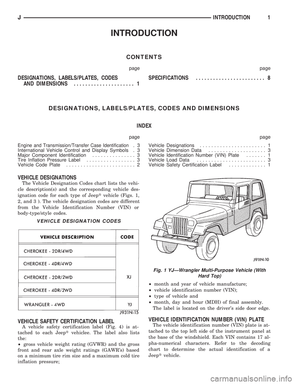
The Vehicle Designation Codes chart lists the vehi-
cle description(s) and the corresponding vehicle des-
ignation code for each type of Jeeptvehicle (Figs. 1,
2, and 3 ). The vehicle designation codes are different
from the Vehicle Identification Number (VIN) or
body-type/style codes.
VEHICLE SAFETY CERTIFICATION LABEL
A vehicle safety certification label (Fig. 4) is at-
tached to each Jeeptvehiclee. The label also lists
the:
²gross vehicle weight rating (GVWR) and the gross
front and rear axle weight ratings (GAWR's) based
on a minimum tire rim size and a maximum cold tire
inflation pressure;²month and year of vehicle manufacture;
²vehicle identification number (VIN);
²type of vehicle and
²month, day and hour (MDH) of final assembly.
The label is located on the driver's side door edge.
VEHICLE IDENTIFICATION NUMBER (VIN) PLATE
The vehicle identification number (VIN) plate is at-
tached to the top left side of the instrument panel at
the base of the windshield. Each VIN contains 17 al-
pha-numerical characters. Refer to the decoding
chart to determine the actual identification of a
Jeeptvehicle.
VEHICLE DESIGNATION CODES
Fig. 1 YJÐWrangler Multi-Purpose Vehicle (With
Hard Top)
JINTRODUCTION1