1994 JEEP CHEROKEE front
[x] Cancel search: frontPage 1602 of 1784
FENDER SPLASH APRONS
REMOVAL
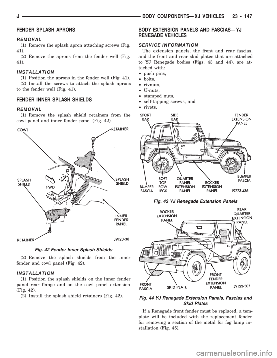
(1) Remove the splash apron attaching screws (Fig.
41).
(2) Remove the aprons from the fender well (Fig.
41).
INSTALLATION
(1) Position the aprons in the fender well (Fig. 41).
(2) Install the screws to attach the splash aprons
to the fender well (Fig. 41).
FENDER INNER SPLASH SHIELDS
REMOVAL
(1) Remove the splash shield retainers from the
cowl panel and inner fender panel (Fig. 42).
(2) Remove the splash shields from the inner
fender and cowl panel (Fig. 42).
INSTALLATION
(1) Position the splash shields on the inner fender
panel rear flange and on the cowl panel extension
(Fig. 42).
(2) Install the splash shield retainers (Fig. 42).
BODY EXTENSION PANELS AND FASCIASÐYJ
RENEGADE VEHICLES
SERVICE INFORMATION
The extension panels, the front and rear fascias,
and the front and rear skid plates that are attached
to YJ Renegade bodies (Figs. 43 and 44). are at-
tached with:
²push pins,
²bolts,
²rivnuts,
²U-nuts,
²stamped nuts,
²self-tapping screws, and
²rivets.
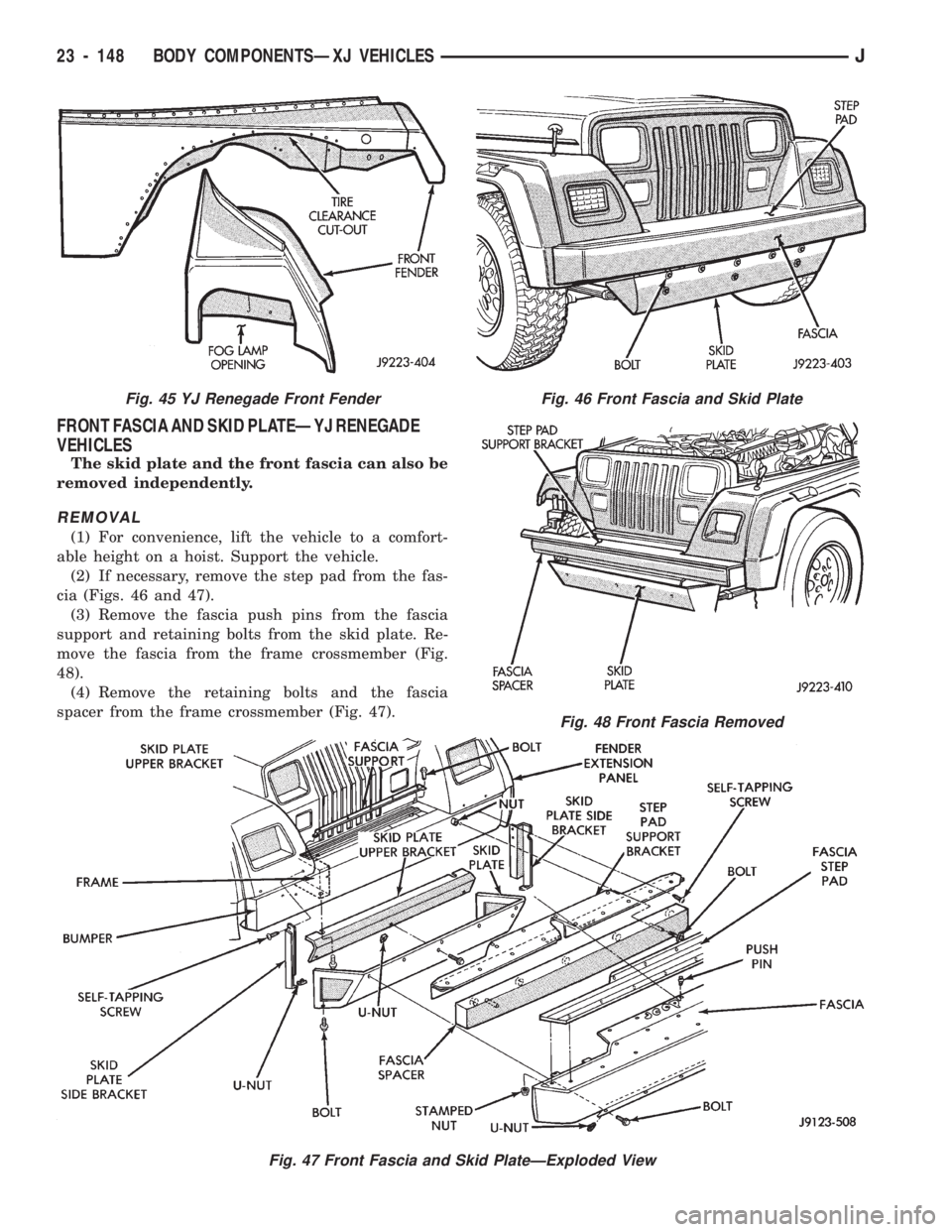
If a Renegade front fender must be replaced, a tem-
plate will be included with the replacement fender
for removing a section of the metal for fog lamp in-
stallation (Fig. 45).
Fig. 42 Fender Inner Splash Shields
Fig. 43 YJ Renegade Extension Panels
Fig. 44 YJ Renegade Extension Panels, Fascias and
Skid Plates
JBODY COMPONENTSÐXJ VEHICLES 23 - 147
Page 1603 of 1784
FRONT FASCIA AND SKID PLATEÐYJ RENEGADE
VEHICLES
The skid plate and the front fascia can also be
removed independently.
REMOVAL
(1) For convenience, lift the vehicle to a comfort-
able height on a hoist. Support the vehicle.
(2) If necessary, remove the step pad from the fas-
cia (Figs. 46 and 47).
(3) Remove the fascia push pins from the fascia
support and retaining bolts from the skid plate. Re-
move the fascia from the frame crossmember (Fig.
48).
(4) Remove the retaining bolts and the fascia
spacer from the frame crossmember (Fig. 47).
Fig. 46 Front Fascia and Skid Plate
Fig. 47 Front Fascia and Skid PlateÐExploded View
Fig. 48 Front Fascia Removed
Fig. 45 YJ Renegade Front Fender
23 - 148 BODY COMPONENTSÐXJ VEHICLESJ
Page 1604 of 1784
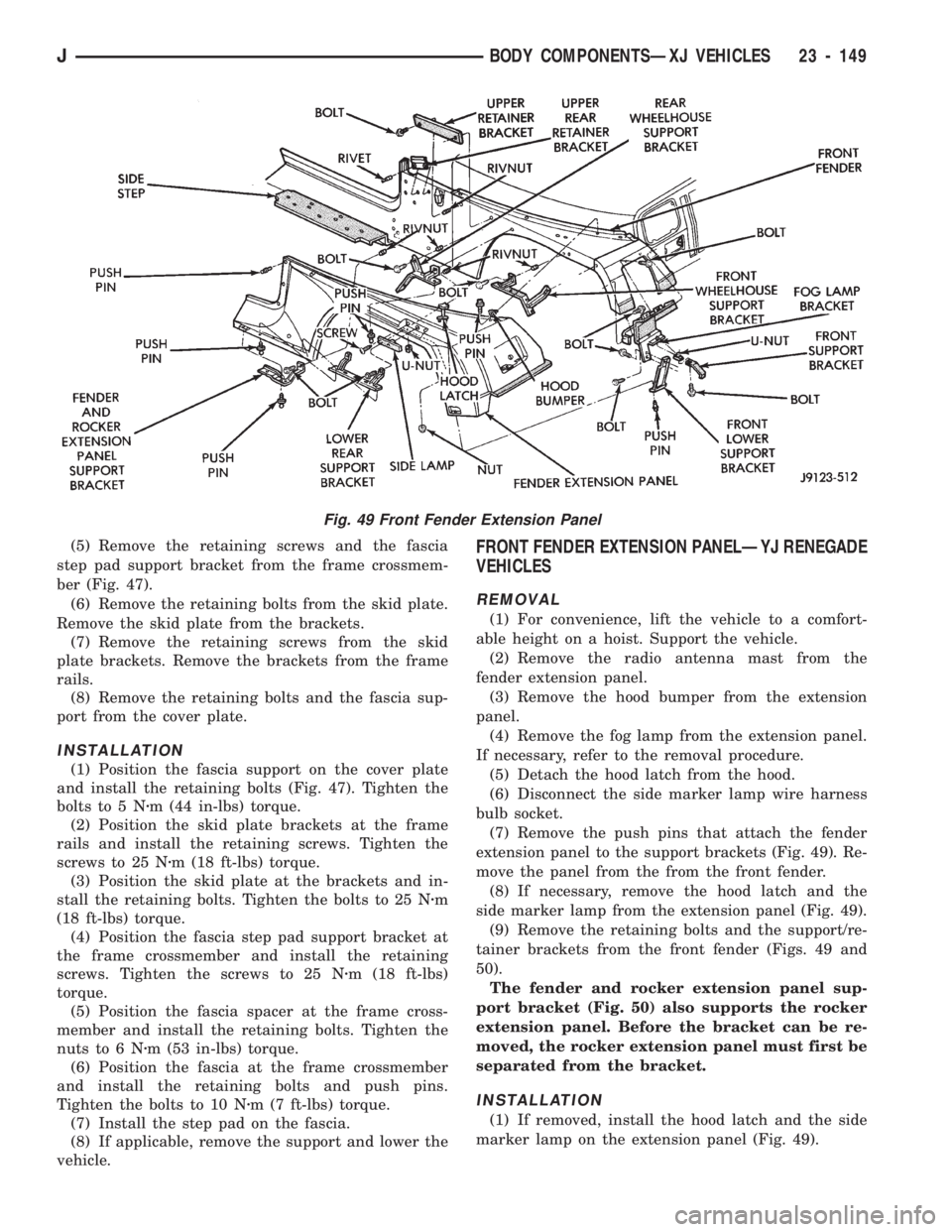
(5) Remove the retaining screws and the fascia
step pad support bracket from the frame crossmem-
ber (Fig. 47).
(6) Remove the retaining bolts from the skid plate.
Remove the skid plate from the brackets.
(7) Remove the retaining screws from the skid
plate brackets. Remove the brackets from the frame
rails.
(8) Remove the retaining bolts and the fascia sup-
port from the cover plate.
INSTALLATION
(1) Position the fascia support on the cover plate
and install the retaining bolts (Fig. 47). Tighten the
bolts to 5 Nzm (44 in-lbs) torque.
(2) Position the skid plate brackets at the frame
rails and install the retaining screws. Tighten the
screws to 25 Nzm (18 ft-lbs) torque.
(3) Position the skid plate at the brackets and in-
stall the retaining bolts. Tighten the bolts to 25 Nzm
(18 ft-lbs) torque.
(4) Position the fascia step pad support bracket at
the frame crossmember and install the retaining
screws. Tighten the screws to 25 Nzm (18 ft-lbs)
torque.
(5) Position the fascia spacer at the frame cross-
member and install the retaining bolts. Tighten the
nuts to 6 Nzm (53 in-lbs) torque.
(6) Position the fascia at the frame crossmember
and install the retaining bolts and push pins.
Tighten the bolts to 10 Nzm (7 ft-lbs) torque.
(7) Install the step pad on the fascia.
(8) If applicable, remove the support and lower the
vehicle.
FRONT FENDER EXTENSION PANELÐYJ RENEGADE
VEHICLES
REMOVAL
(1) For convenience, lift the vehicle to a comfort-
able height on a hoist. Support the vehicle.
(2) Remove the radio antenna mast from the
fender extension panel.
(3) Remove the hood bumper from the extension
panel.
(4) Remove the fog lamp from the extension panel.
If necessary, refer to the removal procedure.
(5) Detach the hood latch from the hood.
(6) Disconnect the side marker lamp wire harness
bulb socket.
(7) Remove the push pins that attach the fender
extension panel to the support brackets (Fig. 49). Re-
move the panel from the from the front fender.
(8) If necessary, remove the hood latch and the
side marker lamp from the extension panel (Fig. 49).
(9) Remove the retaining bolts and the support/re-
tainer brackets from the front fender (Figs. 49 and
50).
The fender and rocker extension panel sup-
port bracket (Fig. 50) also supports the rocker
extension panel. Before the bracket can be re-
moved, the rocker extension panel must first be
separated from the bracket.
INSTALLATION
(1) If removed, install the hood latch and the side
marker lamp on the extension panel (Fig. 49).
Fig. 49 Front Fender Extension Panel
JBODY COMPONENTSÐXJ VEHICLES 23 - 149
Page 1605 of 1784
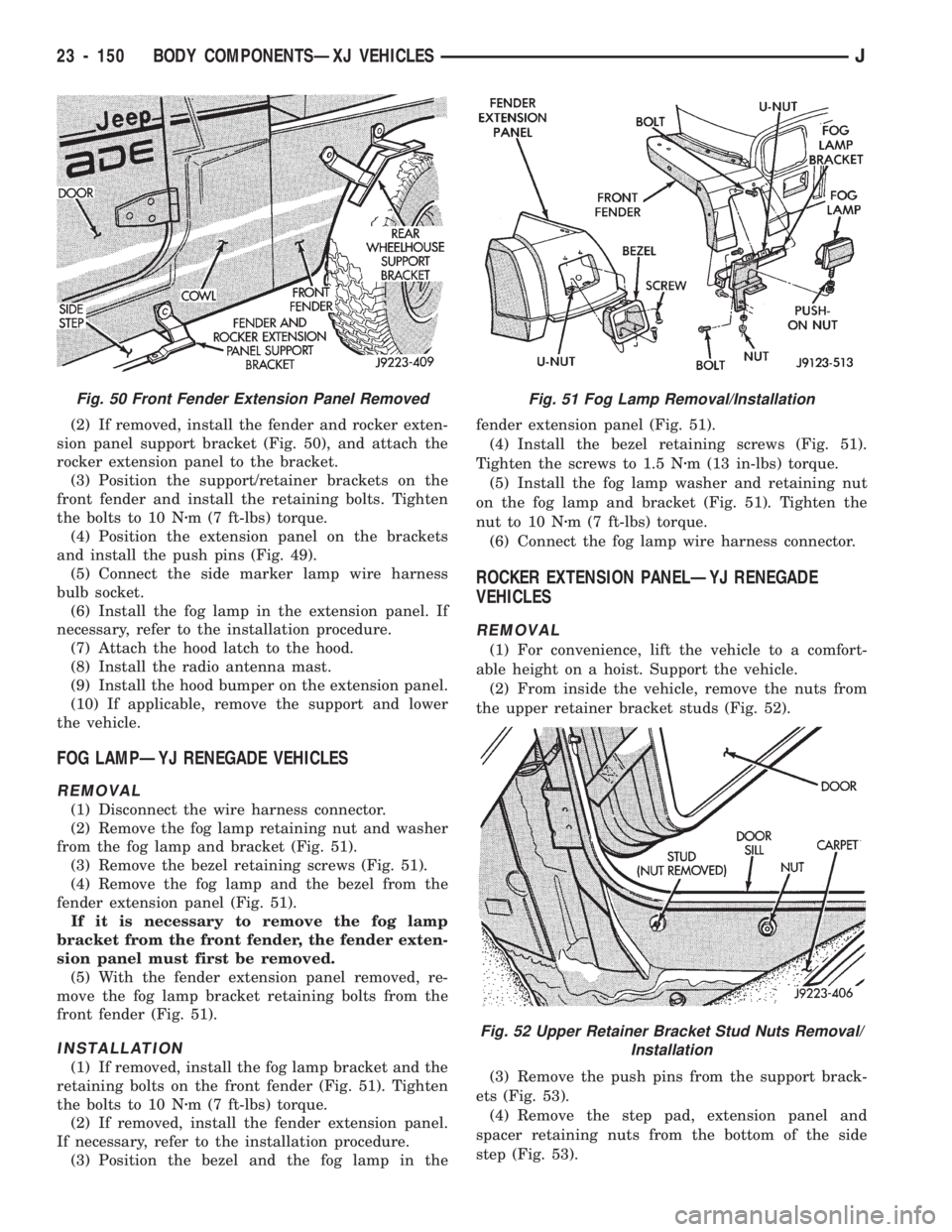
(2) If removed, install the fender and rocker exten-
sion panel support bracket (Fig. 50), and attach the
rocker extension panel to the bracket.
(3) Position the support/retainer brackets on the
front fender and install the retaining bolts. Tighten
the bolts to 10 Nzm (7 ft-lbs) torque.
(4) Position the extension panel on the brackets
and install the push pins (Fig. 49).
(5) Connect the side marker lamp wire harness
bulb socket.
(6) Install the fog lamp in the extension panel. If
necessary, refer to the installation procedure.
(7) Attach the hood latch to the hood.
(8) Install the radio antenna mast.
(9) Install the hood bumper on the extension panel.
(10) If applicable, remove the support and lower
the vehicle.
FOG LAMPÐYJ RENEGADE VEHICLES
REMOVAL
(1) Disconnect the wire harness connector.
(2) Remove the fog lamp retaining nut and washer
from the fog lamp and bracket (Fig. 51).
(3) Remove the bezel retaining screws (Fig. 51).
(4) Remove the fog lamp and the bezel from the
fender extension panel (Fig. 51).
If it is necessary to remove the fog lamp
bracket from the front fender, the fender exten-
sion panel must first be removed.
(5) With the fender extension panel removed, re-
move the fog lamp bracket retaining bolts from the
front fender (Fig. 51).
INSTALLATION
(1) If removed, install the fog lamp bracket and the
retaining bolts on the front fender (Fig. 51). Tighten
the bolts to 10 Nzm (7 ft-lbs) torque.
(2) If removed, install the fender extension panel.
If necessary, refer to the installation procedure.
(3) Position the bezel and the fog lamp in thefender extension panel (Fig. 51).
(4) Install the bezel retaining screws (Fig. 51).
Tighten the screws to 1.5 Nzm (13 in-lbs) torque.
(5) Install the fog lamp washer and retaining nut
on the fog lamp and bracket (Fig. 51). Tighten the
nut to 10 Nzm (7 ft-lbs) torque.
(6) Connect the fog lamp wire harness connector.
ROCKER EXTENSION PANELÐYJ RENEGADE
VEHICLES
REMOVAL
(1) For convenience, lift the vehicle to a comfort-
able height on a hoist. Support the vehicle.
(2) From inside the vehicle, remove the nuts from
the upper retainer bracket studs (Fig. 52).
(3) Remove the push pins from the support brack-
ets (Fig. 53).
(4) Remove the step pad, extension panel and
spacer retaining nuts from the bottom of the side
step (Fig. 53).
Fig. 50 Front Fender Extension Panel RemovedFig. 51 Fog Lamp Removal/Installation
Fig. 52 Upper Retainer Bracket Stud Nuts Removal/
Installation
23 - 150 BODY COMPONENTSÐXJ VEHICLESJ
Page 1606 of 1784
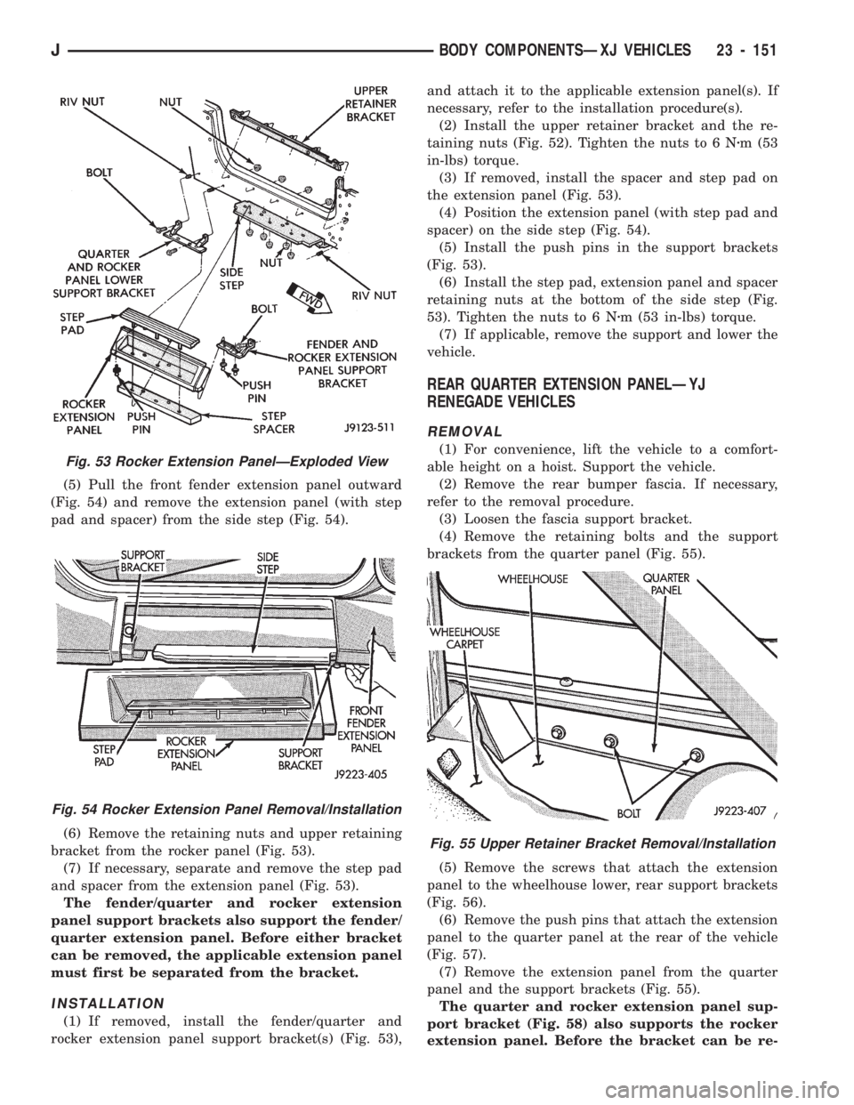
(5) Pull the front fender extension panel outward
(Fig. 54) and remove the extension panel (with step
pad and spacer) from the side step (Fig. 54).
(6) Remove the retaining nuts and upper retaining
bracket from the rocker panel (Fig. 53).
(7) If necessary, separate and remove the step pad
and spacer from the extension panel (Fig. 53).
The fender/quarter and rocker extension
panel support brackets also support the fender/
quarter extension panel. Before either bracket
can be removed, the applicable extension panel
must first be separated from the bracket.
INSTALLATION
(1) If removed, install the fender/quarter and
rocker extension panel support bracket(s) (Fig. 53),and attach it to the applicable extension panel(s). If
necessary, refer to the installation procedure(s).
(2) Install the upper retainer bracket and the re-
taining nuts (Fig. 52). Tighten the nuts to 6 Nzm (53
in-lbs) torque.
(3) If removed, install the spacer and step pad on
the extension panel (Fig. 53).
(4) Position the extension panel (with step pad and
spacer) on the side step (Fig. 54).
(5) Install the push pins in the support brackets
(Fig. 53).
(6) Install the step pad, extension panel and spacer
retaining nuts at the bottom of the side step (Fig.
53). Tighten the nuts to 6 Nzm (53 in-lbs) torque.
(7) If applicable, remove the support and lower the
vehicle.
REAR QUARTER EXTENSION PANELÐYJ
RENEGADE VEHICLES
REMOVAL
(1) For convenience, lift the vehicle to a comfort-
able height on a hoist. Support the vehicle.
(2) Remove the rear bumper fascia. If necessary,
refer to the removal procedure.
(3) Loosen the fascia support bracket.
(4) Remove the retaining bolts and the support
brackets from the quarter panel (Fig. 55).
(5) Remove the screws that attach the extension
panel to the wheelhouse lower, rear support brackets
(Fig. 56).
(6) Remove the push pins that attach the extension
panel to the quarter panel at the rear of the vehicle
(Fig. 57).
(7) Remove the extension panel from the quarter
panel and the support brackets (Fig. 55).
The quarter and rocker extension panel sup-
port bracket (Fig. 58) also supports the rocker
extension panel. Before the bracket can be re-
Fig. 55 Upper Retainer Bracket Removal/Installation
Fig. 53 Rocker Extension PanelÐExploded View
Fig. 54 Rocker Extension Panel Removal/Installation
JBODY COMPONENTSÐXJ VEHICLES 23 - 151
Page 1622 of 1784
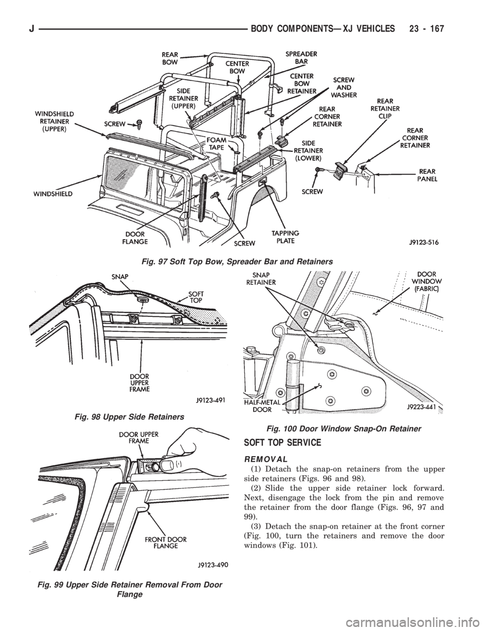
SOFT TOP SERVICE
REMOVAL
(1) Detach the snap-on retainers from the upper
side retainers (Figs. 96 and 98).
(2) Slide the upper side retainer lock forward.
Next, disengage the lock from the pin and remove
the retainer from the door flange (Figs. 96, 97 and
99).
(3) Detach the snap-on retainer at the front corner
(Fig. 100, turn the retainers and remove the door
windows (Fig. 101).
Fig. 97 Soft Top Bow, Spreader Bar and Retainers
Fig. 98 Upper Side Retainers
Fig. 99 Upper Side Retainer Removal From Door
Flange
Fig. 100 Door Window Snap-On Retainer
JBODY COMPONENTSÐXJ VEHICLES 23 - 167
Page 1623 of 1784
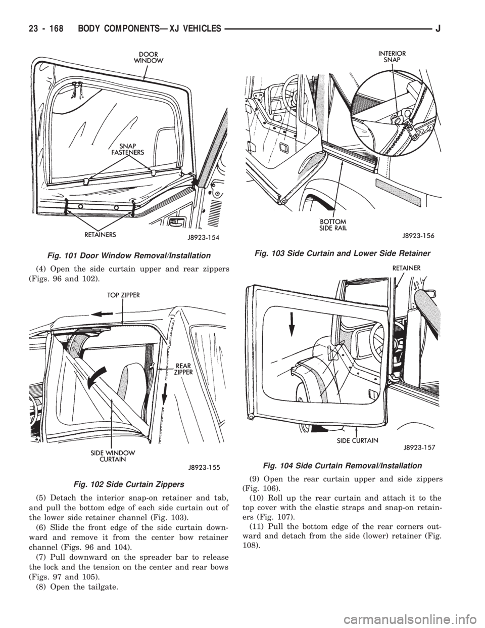
(4) Open the side curtain upper and rear zippers
(Figs. 96 and 102).
(5) Detach the interior snap-on retainer and tab,
and pull the bottom edge of each side curtain out of
the lower side retainer channel (Fig. 103).
(6) Slide the front edge of the side curtain down-
ward and remove it from the center bow retainer
channel (Figs. 96 and 104).
(7) Pull downward on the spreader bar to release
the lock and the tension on the center and rear bows
(Figs. 97 and 105).
(8) Open the tailgate.(9) Open the rear curtain upper and side zippers
(Fig. 106).
(10) Roll up the rear curtain and attach it to the
top cover with the elastic straps and snap-on retain-
ers (Fig. 107).
(11) Pull the bottom edge of the rear corners out-
ward and detach from the side (lower) retainer (Fig.
108).
Fig. 101 Door Window Removal/Installation
Fig. 102 Side Curtain Zippers
Fig. 103 Side Curtain and Lower Side Retainer
Fig. 104 Side Curtain Removal/Installation
23 - 168 BODY COMPONENTSÐXJ VEHICLESJ
Page 1626 of 1784
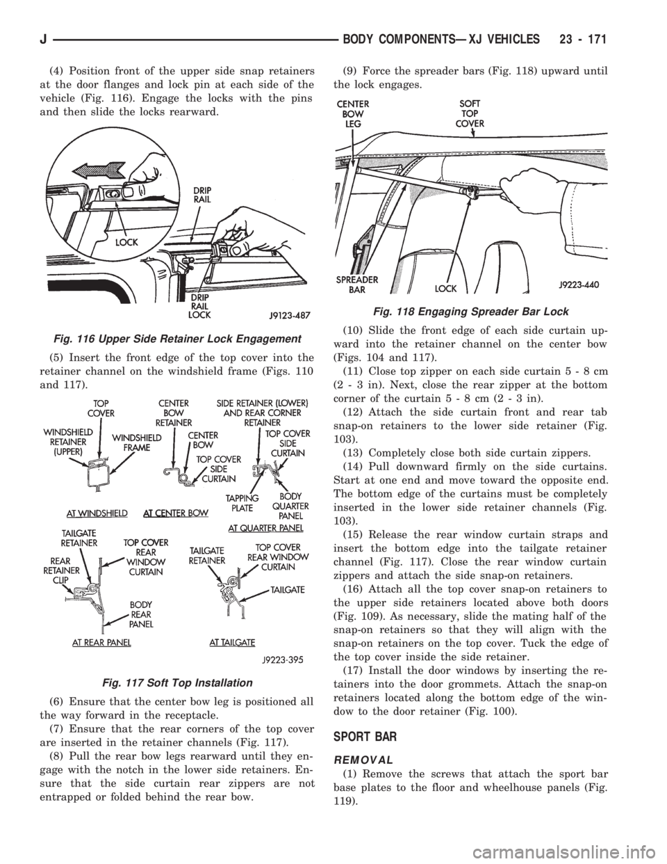
(4) Position front of the upper side snap retainers
at the door flanges and lock pin at each side of the
vehicle (Fig. 116). Engage the locks with the pins
and then slide the locks rearward.
(5) Insert the front edge of the top cover into the
retainer channel on the windshield frame (Figs. 110
and 117).
(6) Ensure that the center bow leg is positioned all
the way forward in the receptacle.
(7) Ensure that the rear corners of the top cover
are inserted in the retainer channels (Fig. 117).
(8) Pull the rear bow legs rearward until they en-
gage with the notch in the lower side retainers. En-
sure that the side curtain rear zippers are not
entrapped or folded behind the rear bow.(9) Force the spreader bars (Fig. 118) upward until
the lock engages.
(10) Slide the front edge of each side curtain up-
ward into the retainer channel on the center bow
(Figs. 104 and 117).
(11) Close top zipper on each side curtain5-8cm
(2 - 3 in). Next, close the rear zipper at the bottom
corner of the curtain5-8cm(2-3in).
(12) Attach the side curtain front and rear tab
snap-on retainers to the lower side retainer (Fig.
103).
(13) Completely close both side curtain zippers.
(14) Pull downward firmly on the side curtains.
Start at one end and move toward the opposite end.
The bottom edge of the curtains must be completely
inserted in the lower side retainer channels (Fig.
103).
(15) Release the rear window curtain straps and
insert the bottom edge into the tailgate retainer
channel (Fig. 117). Close the rear window curtain
zippers and attach the side snap-on retainers.
(16) Attach all the top cover snap-on retainers to
the upper side retainers located above both doors
(Fig. 109). As necessary, slide the mating half of the
snap-on retainers so that they will align with the
snap-on retainers on the top cover. Tuck the edge of
the top cover inside the side retainer.
(17) Install the door windows by inserting the re-
tainers into the door grommets. Attach the snap-on
retainers located along the bottom edge of the win-
dow to the door retainer (Fig. 100).
SPORT BAR
REMOVAL
(1) Remove the screws that attach the sport bar
base plates to the floor and wheelhouse panels (Fig.
119).
Fig. 116 Upper Side Retainer Lock Engagement
Fig. 117 Soft Top Installation
Fig. 118 Engaging Spreader Bar Lock
JBODY COMPONENTSÐXJ VEHICLES 23 - 171