1993 DODGE TRUCK fuel cap
[x] Cancel search: fuel capPage 787 of 1502
11
- 28
EXHAUST
SYSTEM
AND
INTAKE MANIFOLD
•
DESCRIPTION
TORQUE
DESCRIPTION
TORQUE
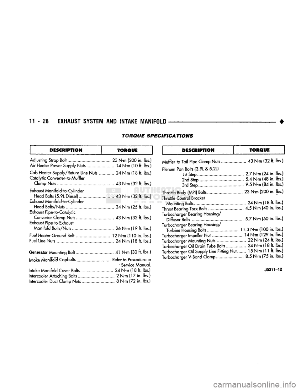
Adjusting
Strop
Bolt
23
N-m
(200 in.
lbs.)
Air Heater Power Supply Nuts 14 N-m (10
ft.
lbs.) Cab
Heater Supply/Return Line Nuts 24
N-m
(18
ft.
lbs.)
Catalytic
Converter-to-Muffler Clamp Nuts 43 N-m (32 ft. lbs.)
Exhaust Manifold-to-Cylinder
Head
Bolts
(5.9L Diesel) 43 N-m (32
ft.
lbs.)
Exhaust Manifold-to-Cylinder
Head Bolts/Nuts 34
N-m (25
ft. lbs.)
Exhaust Pipe-to-Catalytic
Converter Clamp Nuts 43 N-m (32 ft. lbs.)
Exhaust Pipe-to-Exhaust
Manifold
Bolts/Nuts 26 N-m (19 ft. lbs.)
Fuel Heater Ground Bolt . 12 N-m (110 in. lbs.)
Fuel Line Nuts 24 N-m (18ft. lbs.)
Generator Mounting Bolt 41 N-m (30 ft. lbs.) Intake ManiFolcf Capbolts Refer to Procedure
in
Service Manual.
Intake Manifold Cover Bolts 24 N-m (18 ft. lbs.)
Intercooler Attaching Bolts............................. 2 N-m (17 in. lbs.) Intercooler Duct Clamp Nuts 8 N-m (72 in. lbs.) Muffler-to-Tail Pipe Clamp Nuts 43 N-m (32 ft. lbs.)
Plenum Pan Bolts (3.9L
& 5.2L)
1st Step 2.7 N-m (24 in. lbs.)
2nd Step 5.4 N-m (48 in. lbs.)
3rd Step 9.5 N-m (84 in. lbs.)
Throttle Body
(MPI)
Bolts 23 N-m (200 in. lbs.)
Throttle Control Bracket Mounting Bolts 24 N-m (18 ft. lbs.)
Thrust Bearing Torx Bolts............................ 4.5 N-m (40 in. lbs.)
Turbocharger Bearing Housing/ Diffuser Bolts 5.7 N-m (50 in. lbs.)
Turbocharger Bearing Housing/ Turbine Housing Bolts 11.3 N-m (100 in. lbs.)
Turbocharger Impeller Nut 14 N-m (129 in. lbs.) Turbocharger Mounting Nuts 32 N-m (24 ft. lbs.)
Turbocharger Oil Drain Tube Bolts... 24 N-m (18 ft. lbs.) Turbocharger Oil Supply Line Fitting Nut.. 15 N-m (11 ft. lbs.)
Turbocharger V-Band Clamp 8.5 N-m (75 in. lbs.)
J9311-12
TORQUE
SPECIFICATIONS
Page 820 of 1502
•
FUEL
SYSTEM
14 - 1
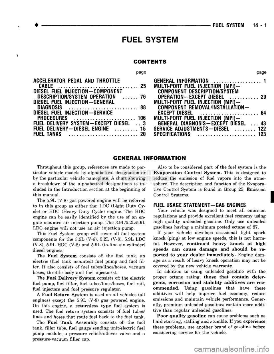
FUEL
SYSTEM
page
ACCELERATOR
PEDAL
AND THROTTLE
CABLE
................ 25
DIESEL
FUEL
INJECTION-COMPONENT
DESCRIPTION/SYSTEM
OPERATION
76
DIESEL
FUEL
INJECTION-GENERAL
DIAGNOSIS
88
DIESEL
FUEL
INJECTION-SERVICE
PROCEDURES
....................... 106
FUEL
DELIVERY
SYSTEM-EXCEPT
DIESEL
.. 3
FUEL
DELIVERY-DIESEL
ENGINE
15
FUEL
TANKS
.... 20
page
GENERAL
INFORMATION 1
MULTI-PORT
FUEL
INJECTION (MPI)-
COMPONENT
DESCRIPTION/SYSTEM
OPERATION-EXCEPT
DIESEL
29
MULTI-PORT
FUEL
INJECTION (MPI)-
COMPONENT
REMOVAL/INSTALLATION-
EXCEPT
DIESEL
64
MULTI-PORT
FUEL
INJECTION (MPI)-
GENERAL
DIAGNOSIS-EXCEPT
DIESEL
...43
SERVICE
ADJUSTMENTS-DIESEL
122
SPECIFICATIONS
123
GENERAL INFORMATION
Throughout this group, references are made to par
ticular vehicle models by alphabetical designation or
by the particular vehicle nameplate. A chart showing a breakdown of the alphabetical designations is in
cluded in the Introduction section at the beginning of
this manual.
The 5.9L (V-8) gas powered engine will be referred
to in this group as either the: LDC (Light Duty Cy cle) or HDC (Heavy Duty Cycle) engine. The HDC engine can be easily identified by the use of an en
gine mounted air injection pump. The 3.9L/5.2L/5.9L
LDC engine will not use an air injection pump.
This Fuel System group will cover all fuel system
components for the 3.9L (V-6), 5.2L (V-8), 5.9L LDC
(V-8),
5.9L HDC (V-8) and 5.9L (in-line six cylinder)
diesel engines.
The Fuel System consists of: the fuel tank, an
electric (fuel tank mounted) fuel pump and fuel fil
ter. It also consists of fuel tubes/lines/hoses, vacuum
hoses,
throttle body and fuel injector(s).
The Fuel Delivery System consists of: the electric
fuel pump, fuel filter, fuel tubes/lines/hoses, fuel rail,
fuel injectors and fuel pressure regulator.
A Fuel Return System is used on all vehicles (all
engines) except the 5.9L (V-8) gas powered engine. On this engine, a returnless type fuel system is
used. The fuel return system consists of fuel tubes/
lines and hoses that route fuel back to the fuel tank.
The Fuel Tank Assembly consists of: the fuel
tank, filler tube, fuel gauge sending unit/electric fuel
pump module, a pressure relief/rollover valve and a
pressure-vacuum filler cap. Also to be considered part of the fuel system is the
Evaporation Control System. This is designed to
reduce the emission of fuel vapors into the atmo sphere. The description and function of the Evapora
tive Control System is found in Group 25, Emission Control Systems.
FUEL
USAGE
STATEMENT-GAS
ENGINES
Your vehicle was designed to meet all emission
regulations and provide excellent fuel economy using
high quality unleaded gasoline. Only use unleaded gasolines having a minimum posted octane of 87. If your vehicle develops occasional light spark
knock (ping) at low engine speeds, this is not harm
ful.
However, continued heavy knock at high speeds can cause damage and should be re
ported to your dealer immediately. Engine dam age as a result of heavy knock operation may not be
covered by the new vehicle warranty. In addition to using unleaded gasoline with the
proper octane rating, those that contain deter
gents,
corrosion and stability additives are rec
ommended. Using gasolines that have these additives will help improve fuel economy, reduce
emissions and maintain vehicle performance. Gener ally, premium unleaded gasolines contain more addi
tive than regular unleaded gasolines. Poor quality gasoline can cause problems such as
hard starting, stalling and stumble. If you experience
these problems, use another brand of gasoline before considering service for the vehicle.
Page 822 of 1502
•
FUEL SYSTEM
14 • 3
FUEL
DELIVERY SYSTEM-EXCEPT DIESEL
INDEX
page
Fuel Filter—3.9L/5.2L Gas Engine
............
10
Fuel
Filter—5.9L
Gas Engine
11
Fuel Pressure Leak Down Test—3.9L/5.2L Engine
. 8
Fuel Pressure Leak Down Test—5.9L Engine
.... 9
Fuel Pump Capacity
Test—All
Gas
Engines
..... 8
Fuel Pump
Control
........................
5
Fuel Pump Module—3.9L/5.2L Engines
3
GENERAL INFORMATION
Two different types
of
fuel delivery/fuel return sys
tems
are
used.
The
system used with
the
3.9L/5.2L
engine will route excess fuel pressure back
to the
fuel tank through
a
fuel return line.
The
system used
with
the 5.9L
engine will
not
have
a
separate fuel
re
turn line. This system will
be
referred
to as a re-
turnless type.
The
fuel pump module used with
the
5.9L engine will contain
a
combination fuel pressure
regulator
and
fuel filter. Refer
to the
following Fuel
Pump Module
for
additional information
or,
refer
to
the Multi-Port Fuel Injection sections
of
this Fuel System group. A separate frame mounted fuel filter will
not be
used with
any 5.9L gas
powered engine.
FUEL
PUMP
M0DULE-3.9L/5.2L
ENGINES
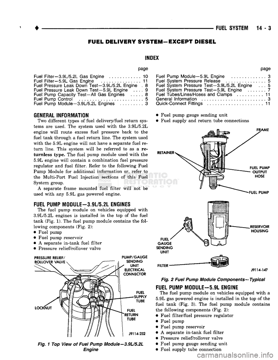
The fuel pump module
on
vehicles equipped with
3.9L/5.2L engines
is
installed
in the top of the
fuel
tank (Fig.
1). The
fuel pump module contains
the
fol lowing components (Fig.
2):
• Fuel pump
• Fuel pump reservoir
•
A
separate in-tank fuel filter
• Pressure relief/rollover valve
PRESSURE
RELIEF/
PUMP/GAUGE
Fig.
1
Top View
of
Fuel
Pump
Module—3.9U5.2L
Engine
page
Fuel Pump Module—5.9L Engine
.............
3
Fuel System Pressure Release
...............
5
Fuel System Pressure Test—3.9L/5.2L Engine
... 5
Fuel System Pressure Test—5.9L Engine
7
Fuel Tubes/Lines/Hoses
and
Clamps
..........
11
General
Information
3
Quick-Connect
Fittings
11
• Fuel pump gauge sending unit
• Fuel supply
and
return tube connections
J9114-147
Fig.
2
Fuel
Pump
Module
Components—Typical
FUEL PUMP MODULE—5.9L ENGINE
The fuel pump module
on
vehicles equipped with
a
5.9L
gas
powered engine
is
installed
in the top of
the
fuel tank
(Fig. 3). The
fuel pump module contains
the following components (Fig.
2):
• Fuel filter/fuel pressure regulator
• Fuel pump • Fuel pump reservoir
•
A
separate in-tank fuel filter
• Pressure relief/rollover valve
• Fuel pump gauge sending unit
• Fuel supply tube connection
Page 824 of 1502
•
FUEL SYSTEM
14-5
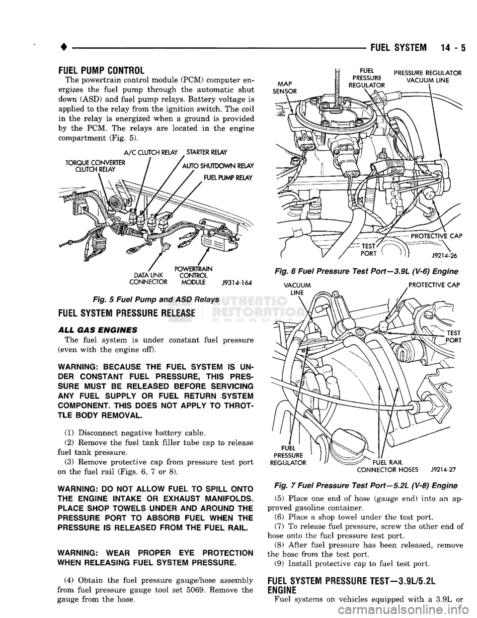
FUEL PUMP CONTROL
The powertrain control module (PCM) computer en
ergizes the fuel pump through the automatic shut
down (ASD) and fuel pump relays. Battery voltage is applied to the relay from the ignition switch. The coil
in the relay is energized when a ground is provided
by the PCM. The relays are located in the engine compartment (Fig. 5).
DATA
UNK
CONTROL
CONNECTOR
MODULE
J9314-164
Fig.
5
Fuel
Pump
and ASD
Relays
FUEL
SYSTEM
PRESSURE
RELEASE
ALL
GAS
ENGINES
The fuel system is under constant fuel pressure
(even with the engine off).
WARNING: BECAUSE THE FUEL SYSTEM IS UN DER CONSTANT FUEL PRESSURE, THIS PRES
SURE MUST BE RELEASED BEFORE SERVICING
ANY FUEL SUPPLY OR FUEL RETURN SYSTEM COMPONENT. THIS DOES NOT APPLY TO THROT
TLE BODY REMOVAL.
(1) Disconnect negative battery cable.
(2) Remove the fuel tank filler tube cap to release
fuel tank pressure. (3) Remove protective cap from pressure test port
on the fuel rail (Figs. 6, 7 or 8).
WARNING: DO NOT ALLOW FUEL TO SPILL ONTO
THE ENGINE INTAKE OR EXHAUST MANIFOLDS. PLACE SHOP TOWELS UNDER AND AROUND THE
PRESSURE PORT TO ABSORB FUEL WHEN THE
PRESSURE IS RELEASED FROM THE FUEL RAIL.
WARNING: WEAR PROPER EYE PROTECTION
WHEN RELEASING FUEL SYSTEM PRESSURE.
(4) Obtain the fuel pressure gauge/hose assembly
from fuel pressure gauge tool set 5069. Remove the
gauge from the hose.
CONNECTOR
HOSES
J9214-27
Fig.
7
Fuel
Pressure
Test Port—5.2L (V-8)
Engine
(5) Place one end of hose (gauge end) into an ap
proved gasoline container. (6) Place a shop towel under the test port.
(7) To release fuel pressure, screw the other end of
hose onto the fuel pressure test port.
(8) After fuel pressure has been released, remove
the hose from the test port. (9) Install protective cap to fuel test port.
FUEL SYSTEM
PRESSURE
TEST-3.9L/5.2L
ENGINE
Fuel systems on vehicles equipped with a 3.9L or
Page 825 of 1502
14-6 FUEL
SYSTEM
•
I
l /////
PROTECTIVE
CAP AND
TEST
PORT
J9314-168
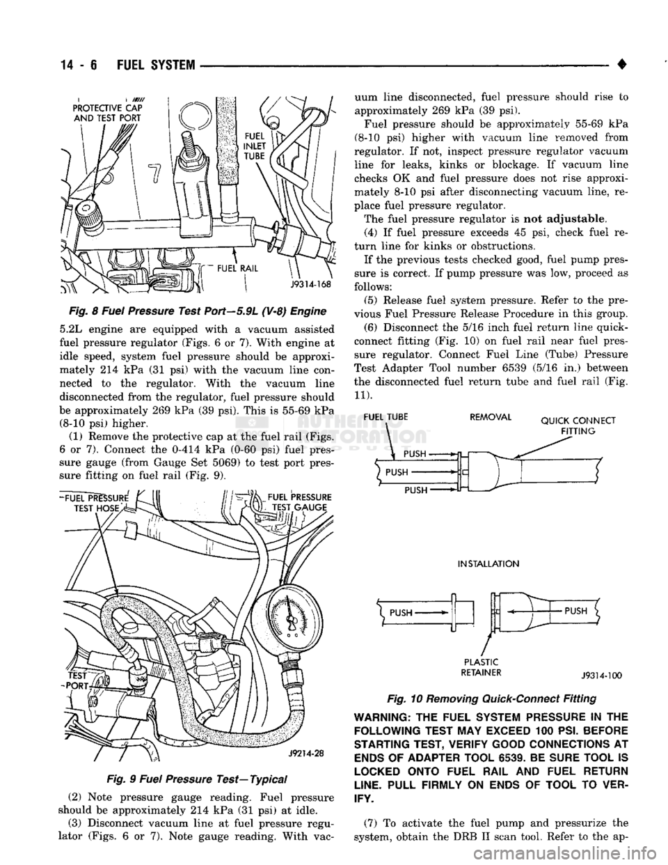
Fig.
8
Fuel
Pressure
Test Port—5.9L (V-8)
Engine
5.2L engine are equipped with a vacuum assisted
fuel pressure regulator (Figs. 6 or 7). With engine at
idle speed, system fuel pressure should be approxi
mately 214 kPa (31 psi) with the vacuum line con
nected to the regulator. With the vacuum line
disconnected from the regulator, fuel pressure should
be approximately 269 kPa (39 psi). This is 55-69 kPa (8-10 psi) higher.
(1) Remove the protective cap at the fuel rail (Figs.
6 or 7). Connect the 0-414 kPa (0-60 psi) fuel pres
sure gauge (from Gauge Set 5069) to test port pres
sure fitting on fuel rail (Fig. 9).
FUEL
PRESSURE
TEST GAUGE
J9214-28
Fig.
9
Fuel
Pressure
Test—
Typical
(2) Note pressure gauge reading. Fuel pressure
should be approximately 214 kPa (31 psi) at idle. (3) Disconnect vacuum line at fuel pressure regu
lator (Figs. 6 or 7). Note gauge reading. With vac uum line disconnected, fuel pressure should rise to
approximately 269 kPa (39 psi).
Fuel pressure should be approximately 55-69 kPa
(8-10 psi) higher with vacuum line removed from
regulator. If not, inspect pressure regulator vacuum line for leaks, kinks or blockage. If vacuum line
checks OK and fuel pressure does not rise approxi
mately 8-10 psi after disconnecting vacuum line, re
place fuel pressure regulator.
The fuel pressure regulator is not adjustable. (4) If fuel pressure exceeds 45 psi, check fuel re
turn line for kinks or obstructions. If the previous tests checked good, fuel pump pres
sure is correct. If pump pressure was low, proceed as
follows:
(5) Release fuel system pressure. Refer to the pre
vious Fuel Pressure Release Procedure in this group. (6) Disconnect the 5/16 inch fuel return line quick-
connect fitting (Fig. 10) on fuel rail near fuel pres
sure regulator. Connect Fuel Line (Tube) Pressure
Test Adapter Tool number 6539 (5/16 in.) between
the disconnected fuel return tube and fuel rail (Fig.
11).
FUEL TUBE REMOVAL
QUICK CONNECT
FITTING
PUSH
INSTALLATION
X
PUSH-
/
PUSH
PLASTIC
RETAINER
J9314-100
Fig.
10
Removing
Quick-Connect
Fitting
WARNING:
THE
FUEL SYSTEM
PRESSURE
IN THE
FOLLOWING TEST
MAY
EXCEED
100
PSI.
BEFORE
STARTING TEST, VERIFY GOOD CONNECTIONS
AT
ENDS
OF
ADAPTER TOOL
6539.
BE
SURE TOOL
IS
LOCKED
ONTO FUEL RAIL
AND
FUEL RETURN
LINE.
PULL FIRMLY
ON
ENDS
OF
TOOL
TO
VER
IFY.
(7) To activate the fuel pump and pressurize the
system, obtain the DRB II scan tool. Refer to the ap-
Page 826 of 1502
•
FUEL
SYSTEM
14 - 7
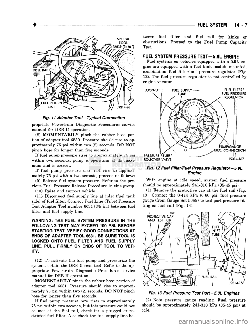
Fig.
1"f
Adapter Tool—Typical
Connection
propriate Powertrain Diagnostic Procedures service
manual for DRB II operation.
(8) MOMENTARILY pinch the rubber hose por
tion of adapter tool 6539. Pressure should rise to ap
proximately 75 psi within two (2) seconds. DO NOT
pinch hose for longer than five seconds.
If fuel pump pressure rises to approximately 75 psi
within two seconds, pump is operating at its maxi mum and is correct. If fuel pump pressure does not rise to approxi
mately 75 psi within two seconds, proceed as follows:
(9) Release fuel system pressure. Refer to the pre
vious Fuel Pressure Release Procedure in this group. (10) Raise and support vehicle.
(11) Disconnect fuel supply line at inlet (fuel tank
side) of fuel filter. Connect Fuel Line (Tube) Pressure
Test Adapter Tool number 6631 (3/8 in.) between fuel
filter and fuel supply line.
WARNING:
THE
FUEL SYSTEM
PRESSURE
IN THE
FOLLOWING TEST MAY EXCEED
100
PSI. BEFORE
STARTING TEST, VERIFY GOOD CONNECTIONS
AT
ENDS
OF
ADAPTER TOOL 6631.
BE
SURE TOOL
IS
LOCKED
ONTO FUEL FILTER
AND
FUEL SUPPLY
LINE.
PULL FIRMLY
ON
ENDS
OF
TOOL
TO
VER
IFY.
(12) To activate the fuel pump and pressurize the
system, obtain the DRB II scan tool. Refer to the ap
propriate Powertrain Diagnostic Procedures service manual for DRB II operation.
MOMENTARILY pinch the rubber hose portion of
adapter tool 6631. Pressure should rise to approxi
mately 75 psi within two (2) seconds. DO NOT pinch
hose for longer than five seconds.
If fuel pump pressure now rises to approximately
75 psi within two seconds, but this pressure could not
be met at the fuel rail, check for a plugged or re stricted fuel filter. Also check the fuel supply line be tween fuel filter and fuel rail for kinks or
obstructions. Proceed to the Fuel Pump Capacity
Test.
FUEL
SYSTEM PRESSURE
TEST—5.9L
ENGINE
Fuel systems on vehicles equipped with a 5.9L en
gine are equipped with a fuel tank module mounted,
combination fuel filter/fuel pressure regulator (Fig.
12).
The fuel pressure regulator is not controlled by
engine vacuum.
ROLLOVER VALVE J9314-167 Fig.
12
Fuel
Filter/Fuel
Pressure
Regulator—5.9L
Engine
With engine at idle speed, system fuel pressure
should be approximately 241-310 kPa (35-45 psi). (1) Remove the protective cap at the fuel rail (Fig.
13).
Connect the 0-414 kPa (0-60 psi) fuel pressure
gauge (from Gauge Set 5069) to test port pressure fit
ting on fuel rail (Fig. 14).
Fig.
13
Fuel
Pressure
Test Port—5.9L
Engines
(2) Note pressure gauge reading. Fuel pressure
should be approximately 241-310 kPa (35-45 psi) at
idle.
Page 827 of 1502
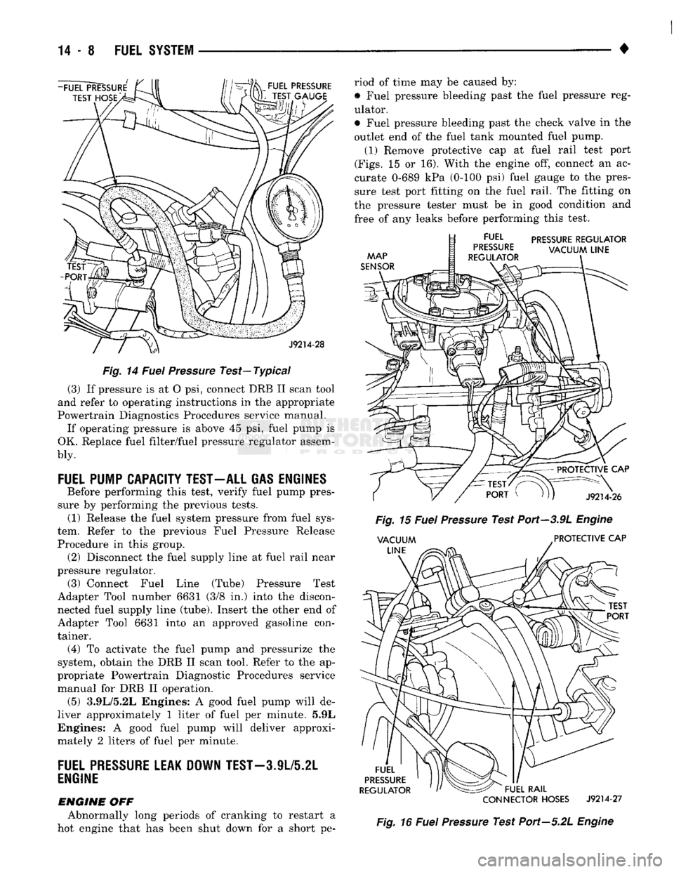
Fig.
14
Fuel
Pressure
Test—Typical
(3) If pressure is at O psi, connect DRB II scan tool
and refer to operating instructions in the appropriate
Powertrain Diagnostics Procedures service manual. If operating pressure is above 45 psi, fuel pump is
OK. Replace fuel filter/fuel pressure regulator assem-
bly.
FUEL
PUMP CAPACITY TEST-ALL GAS ENGINES
Before performing this test, verify fuel pump pres
sure by performing the previous tests. (1) Release the fuel system pressure from fuel sys
tem. Refer to the previous Fuel Pressure Release
Procedure in this group. (2) Disconnect the fuel supply line at fuel rail near
pressure regulator. (3) Connect Fuel Line (Tube) Pressure Test
Adapter Tool number 6631 (3/8 in.) into the discon nected fuel supply line (tube). Insert the other end of
Adapter Tool 6631 into an approved gasoline con
tainer.
(4)
To activate the fuel pump and pressurize the
system, obtain the DRB II scan tool. Refer to the ap
propriate Powertrain Diagnostic Procedures service manual for DRB II operation. (5) 3.9L/5.2L Engines: A good fuel pump will de
liver approximately 1 liter of fuel per minute. 5.9L
Engines: A good fuel pump will deliver approxi
mately 2 liters of fuel per minute.
FUEL
PRESSURE
LEAK DOWN
TEST-3
JL/5.2L
ENGINE
ENGINE
OFF Abnormally long periods of cranking to restart a
hot engine that has been shut down for a short pe riod of time may be caused by:
• Fuel pressure bleeding past the fuel pressure reg
ulator.
• Fuel pressure bleeding past the check valve in the
outlet end of the fuel tank mounted fuel pump. (1) Remove protective cap at fuel rail test port
(Figs.
15 or 16). With the engine off, connect an ac
curate 0-689 kPa (0-100 psi) fuel gauge to the pres
sure test port fitting on the fuel rail. The fitting on
the pressure tester must be in good condition and
free of any leaks before performing this test.
PRESSURE
REGULATOR
CONNECTOR
HOSES
J9214-27
Fig.
16
Fuel
Pressure
Test Port—5.2L
Engine
Page 839 of 1502
14-20 FUEL
SYSTEM
•
FUEL
TANKS
INDEX
page
Fuel Gauge Sending
Unit
24
Fuel Pump
22
Fuel Reservoir
23
Fuel Tank
Filler
Tube
Cap 20
Fuel Tank Pressure Relief/Rollover Valve
...... 24
GENERAL
INFORMATION
All Dodge Trucks pass a full 360 degree rollover with
out fuel leakage. To accomplish this, fuel and vapor
flow controls are required for all fuel tank connections. All models have a pressure relief/rollover valve
mounted in the top of the fuel tank. On vehicles equipped with a return line from fuel pump to fuel
tank, a one-way check valve is used to provide required
protection. In addition to the valve, improved flow con trol is used in the fuel pump. Fuel flow is controlled if
pump is subjected to higher than normal pressure dur ing rollover. For the same reason, a fuel tank filler tube
cap (gas cap) with higher pressure setting is used to
control fuel flow on vehicles with side fill. An evaporation control system is used to reduce
emissions of fuel vapors into atmosphere by evapora
tion and to reduce unburned hydrocarbons emitted
by vehicle engine. When fuel evaporates from fuel
tank, vapors pass through vent hoses or tubes to a
charcoal canister. The are temporarily held in the
canister. When the engine is running, the vapors are
drawn into intake manifold. Refer to Group 25,
Emission Control System for additional information. Inspect all hose connections to make sure they are
secure and not leaking. Hoses should be replaced im
mediately if there is any evidence of degradation
that could result in failure. Avoid contact with clamps or other components
that cause abrasions or scuffing. Be sure that the
rubber hoses are properly routed to prevent pinching and to avoid heat sources.
The hoses used on fuel injected vehicles are of a
special construction due to higher fuel pressures in
volved in system. If hoses need replacement, only use
hoses marked EFM/EFI.
The hose clamps used on fuel injected vehicles have
a special rolled edge construction. This prevents the
edge of the clamp from cutting into the hose. Only
these rolled edge type clamps may be used on this system. Other clamps may cut into the hoses. This
could cause high pressure fuel leaks.
NO-LEAD FUEL TANK FILLER TUBE
All catalyst equipped vehicles have a special fuel
tank filler tube. The fuel filler opening is smaller in
page
Fuel Tank Skid
Plate
. 20
Fuel Tanks
21
General
Information
20
Heat Shields
21
No-Lead
Fuel Tank
Filler
Tube
20
diameter than those used for non-catalyst vehicles to
permit entry of only the smaller no-lead fuel nozzles.
A deflector is installed in the fuel filler opening. The
deflector is opened by the no-lead fuel nozzle. The fuel filler tube on these models has a one-way
ball check valve. The valve is designed to prevent
fuel back splash which may occur while filling the tank. A label is attached to instrument panel under fuel
gauge that reads UNLEADED FUEL ONLY as a re
minder to driver. A similar label is located near fuel
tank filler.
FUEL TANK FILLER TUBE
CAP The loss of any fuel or vapor out of filler neck is
prevented by the use of a pressure-vacuum fuel tank
filler tube cap. Relief valves inside cap will release only under significant pressure of 6.58 to 8.44 kPa (1.95 to 2.5 psi). The vacuum release for all gas caps
is between .97 and 2.0 kPa (.14 and .29 psi). This cap
must be replaced by a similar unit if replacement is necessary. This is in order for the system to remain
effective.
CAUTION:
Remove
fuel
tank
filler
tube
cap
before
servicing
any
fuel
system component. This
is
done
to help
relieve
tank pressure.
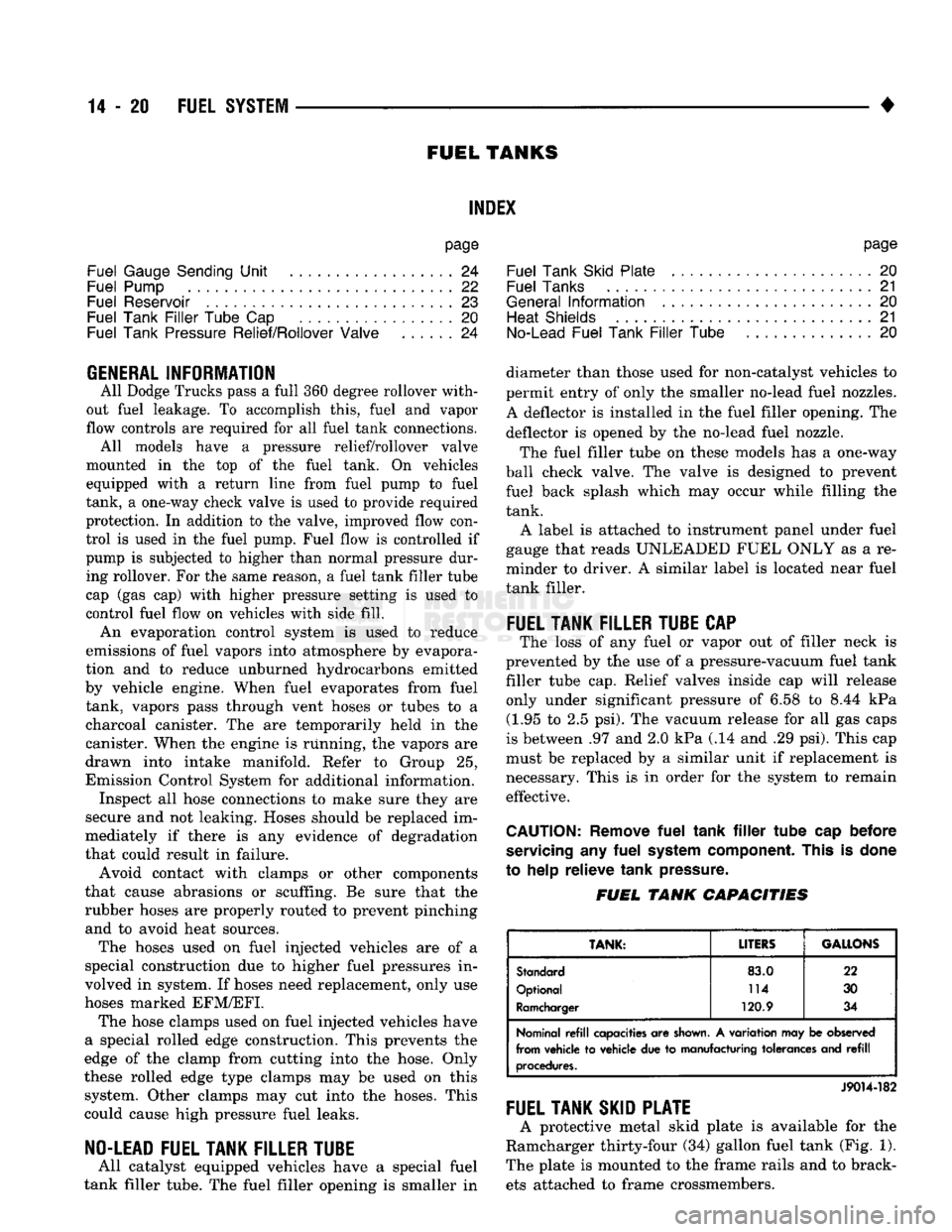
FUEL
TANK
CAPACITIES
TANK:
LITERS
GALLONS
Standard
83.0
22
Optional 114
30
Ramcharger 120.9 34
Nominal
refill
capacities are
shown.
A variation may be observed
from vehicle to vehicle due to manufacturing tolerances and
refill
procedures.
J9014-182
FUEL TANK SKID PLATE
A protective metal skid plate is available for the
Ramcharger thirty-four (34) gallon fuel tank (Fig. 1).
The plate is mounted to the frame rails and to brack ets attached to frame crossmembers.