1993 DODGE TRUCK fuel cap
[x] Cancel search: fuel capPage 928 of 1502
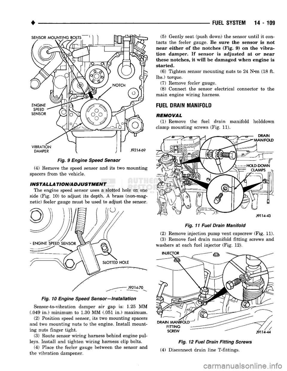
SENSOR
MOUNTING BOLTS
VIBRATION
DAMPER
J9214-69
Fig.
9
Engine Speed Sensor
(4) Remove the speed sensor and its two mounting
spacers from the vehicle.
INST
ALL A
TION/ADJUSTMENT
The engine speed sensor uses a slotted hole on one
side (Fig. 10) to adjust its depth. A brass (non-mag
netic) feeler gauge must be used to adjust the sensor.
Fig.
10
Engine Speed
Sensor—Installation
Sensor-to-vibration damper air gap is: 1.25 MM
(.049 in.) minimum to 1.30 MM (.051 in.) maximum.
(2) Position speed sensor, its two mounting spacers
and two mounting nuts to the engine. Install mount
ing nuts finger tight.
(3) Route sensor wiring harness behind engine pul
leys.
Install and tighten wiring harness clip bolts. (4) Place the feeler gauge between the sensor and
the vibration dampener. (5) Gently seat (push down) the sensor until it con
tacts the feeler gauge. Be sure the sensor is not
near either of the notches (Fig. 9) on the vibra
tion damper. If sensor is adjusted at or near
these notches, it will be damaged when engine is started.
(6) Tighten sensor mounting nuts to 24 N#m (18 ft.
lbs.) torque.
(7) Remove feeler gauge.
(8) Connect the sensor electrical connector to the
main engine wiring harness.
FUEL
DRAIN
MANIFOLD
REMOVAL
(1) Remove the fuel drain manifold holddown
clamp mounting screws (Fig. 11).
DRAIN
MANIFOLD
J9114-43
Fig.
11
Fuel
Drain Manifold
(2) Remove injection pump vent capscrew (Fig. 11).
(3) Remove fuel drain manifold fitting screws and
washers at each fuel injector (Fig. 12).
INJECTOR
DRAIN
MANIFOLD
FITTING
SCREW
J9114-44
Fig.
12
Fuel
Drain
Fitting
Screws
(4) Disconnect drain line T-fittings.
Page 929 of 1502
14
- 110
FUEL SYSTEM
SENSOR
J9114-39
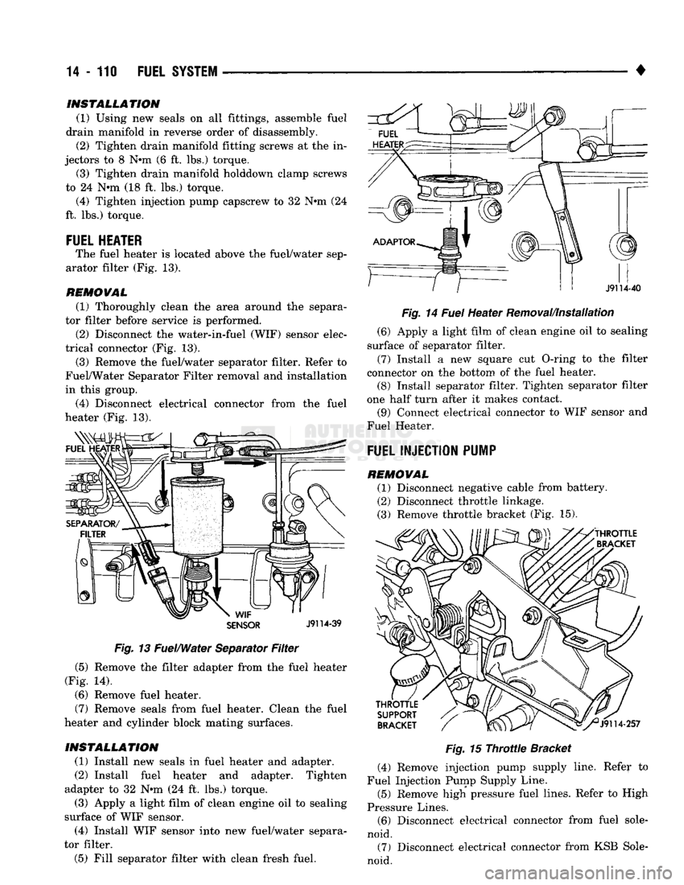
Fig.
13 Fuel/Water Separator
Filter
(5) Remove the filter adapter from the fuel heater
(Fig. 14).
(6) Remove fuel heater.
(7) Remove seals from fuel heater. Clean the fuel
heater and cylinder block mating surfaces.
INSTALLATION
(1) Install new seals in fuel heater and adapter.
(2) Install fuel heater and adapter. Tighten
adapter to 32 Nrn (24 ft. lbs.) torque. (3) Apply a light film of clean engine oil to sealing
surface of WIF sensor.
(4) Install WIF sensor into new fuel/water separa
tor filter.
(5) Fill separator filter with clean fresh fuel. •
Fig.
14
Fuel
Heater Removal/Installation (6) Apply a light film of clean engine oil to sealing
surface of separator filter.
(7) Install a new square cut O-ring to the filter
connector on the bottom of the fuel heater. (8) Install separator filter. Tighten separator filter
one half turn after it makes contact. (9) Connect electrical connector to WIF sensor and
Fuel Heater.
FUEL INJECTION PUMP
REMOVAL (1) Disconnect negative cable from battery.
(2) Disconnect throttle linkage.
(3) Remove throttle bracket (Fig. 15).
Fig.
15
Throttle
Bracket
(4) Remove injection pump supply line. Refer to
Fuel Injection Pump Supply Line.
(5) Remove high pressure fuel lines. Refer to High
Pressure Lines. (6) Disconnect electrical connector from fuel sole
noid. (7) Disconnect electrical connector from KSB Sole
noid.
INSTALLATION
(1) Using new seals on all fittings, assemble fuel
drain manifold in reverse order of disassembly. (2) Tighten drain manifold fitting screws at the in
jectors to 8 N#m (6 ft. lbs.) torque. (3) Tighten drain manifold holddown clamp screws
to 24 N*m (18 ft. lbs.) torque. (4) Tighten injection pump capscrew to 32 N#m (24
ft. lbs.) torque.
FUEL HEATER
The fuel heater is located above the fuel/water sep
arator filter (Fig. 13).
REMOVAL
(1) Thoroughly clean the area around the separa
tor filter before service is performed.
(2) Disconnect the water-in-fuel (WIF) sensor elec
trical connector (Fig. 13). (3) Remove the fuel/water separator filter. Refer to
Fuel/Water Separator Filter removal and installation
in this group.
(4) Disconnect electrical connector from the fuel
heater (Fig. 13).
Page 930 of 1502
•
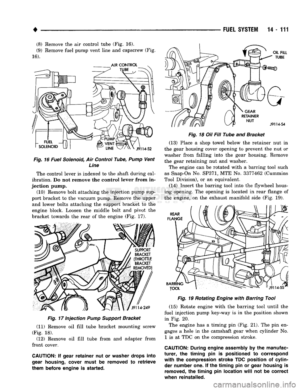
(8) Remove the air control tube (Fig. 16).
(9) Remove fuel pump vent line and capscrew (Fig.
16).
Fig.
16 Fuel Solenoid, Air Control Tube,
Pump
Vent Line
The control lever is indexed to the shaft during cal
ibration. Do not remove the control lever from in
jection pump. (10) Remove bolt attaching the injection pump sup
port bracket to the vacuum pump. Remove the upper and lower bolts attaching the support bracket to the
engine block. Loosen the middle bolt and pivot the
bracket towards the rear of the engine (Fig. 17).
Fig.
17 Injection
Pump
Support
Bracket
(11) Remove oil fill tube bracket mounting screw
(Fig. 18). (12) Remove oil fill tube from and adapter from
front cover.
CAUTION:
If
gear
retainer
nut or
washer drops into
gear
housing,
cover must
be
removed
to
retrieve
them before engine
is
started. FUEL
SYSTEM
14-111
Fig.
18 Oil Fill Tube and Bracket (13) Place a shop towel below the retainer nut in
the gear housing cover opening to prevent the nut or
washer from falling into the gear housing. Remove
the gear retaining nut and washer.
The engine can be rotated with a barring tool such
as Snap-On No.
SP371,
MTE No. 3377462 (Cummins
Tool Division), or an equivalent.
(14) Insert the barring tool into the flywheel hous
ing opening. The opening is located in rear flange of
the engine, on the exhaust manifold side (Fig. 19).
Fig.
19 Rotating
Engine
with
Barring Tool
(15) Rotate engine with the barring tool until the
fuel injection pump key-way is in the position shown in Fig. 20.
The engine has a timing pin (Fig. 21). The pin en
gages a hole in the camshaft gear when cylinder No. 1 is at TDC on the compression stroke.
CAUTION:
During
engine
assembly
by the
manufac
turer,
the
timing
pin is
positioned
to
correspond
with
the
compression stroke TDC position
of
cylin der number one.
If the
timing
pin or
gear housing
is
removed,
the
timing
pin
location
will
not be
correct
when reinstalled.
Page 933 of 1502
14 - 114
FUEL
SYSTEM
• (15) Install fuel injection pump supply line. Refer
to Fuel Injection Pump Supply Line.
(16) Connect electrical connector to fuel solenoid.
(17) Connect electrical connector to KSB solenoid.
(18) Install fuel pump vent line and capscrew.
(19) Install air fuel control tube.
(20) Install throttle bracket (Fig. 15). Tighten
mounting bolts to 24 N»m (18 ft. lbs.) torque.
(21) Install throttle linkage. When connecting the
cable to the control lever, adjust the length so the le
ver has stop-to-stop movement. Refer to Accelerator
Pedal and Throttle Controls section of Group 14,
Fuel Systems.
(22) Install and adjust throttle position sensor. Re
fer to Service Adjustments.
(23) Bleed air from fuel system. Refer to High
Pressure Fuel Lines in the Air Bleeding portion of
the Diesel Fuel Injection section of Group 14, Fuel Systems. (24) Adjust the low idle speed if required. Refer to
Service Adjustments near the end of this group. (25) Inspect throttle linkage to be sure that the
control lever breaks over the full throttle position.
Adjust as necessary. Refer to Accelerator Pedal and
Throttle Cable section of Group 14, Fuel Systems.
FUEL
INJECTION
PUMP
SUPPLY
LINE
REMOVAL
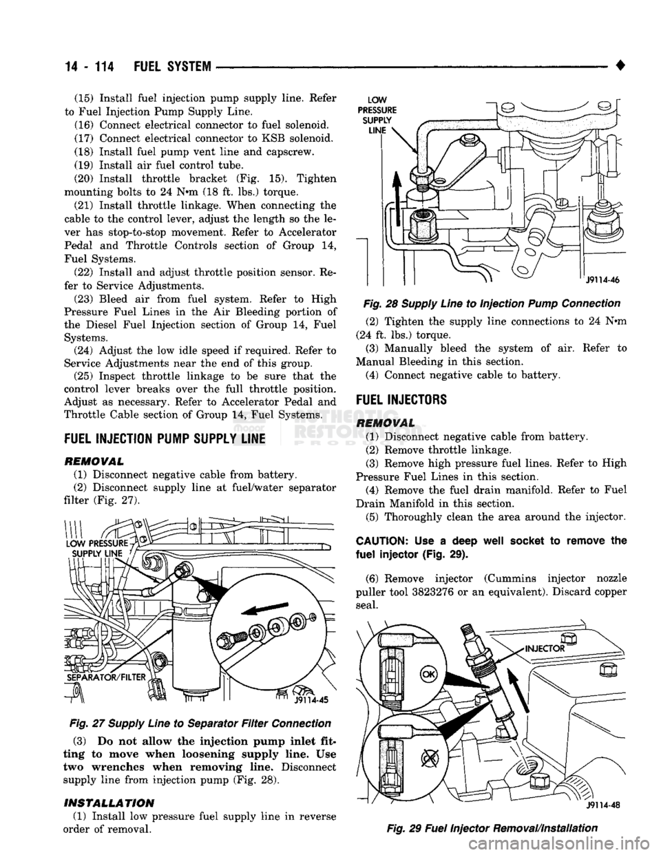
(1) Disconnect negative cable from battery.
(2) Disconnect supply line at fuel/water separator
filter (Fig. 27).
Fig.
27
Supply
Line
to Separator
Filter
Connection
(3) Do not allow the injection pump inlet fit
ting to move when loosening supply line. Use two wrenches when removing line. Disconnect
supply line from injection pump (Fig. 28).
INSTALLATION
(1) Install low pressure fuel supply line in reverse
order of removal.
Fig.
28
Supply
Line
to Injection
Pump
Connection
(2) Tighten the supply line connections to 24 Nnn
(24 ft. lbs.) torque.
(3) Manually bleed the system of air. Refer to
Manual Bleeding in this section.
(4) Connect negative cable to battery.
FUEL
INJECTORS
REMOVAL
(1) Disconnect negative cable from battery.
(2) Remove throttle linkage.
(3) Remove high pressure fuel lines. Refer to High
Pressure Fuel Lines in this section. (4) Remove the fuel drain manifold. Refer to Fuel
Drain Manifold in this section. (5) Thoroughly clean the area around the injector.
CAUTION:
Use a deep
well
socket
to remove the
fuel
injector (Fig. 29).
(6) Remove injector (Cummins injector nozzle
puller tool 3823276 or an equivalent). Discard copper seal.
Fig.
29
Fuel
Injector Removal/Installation
Page 942 of 1502
•
FUEL
SYSTEM
14 - 123
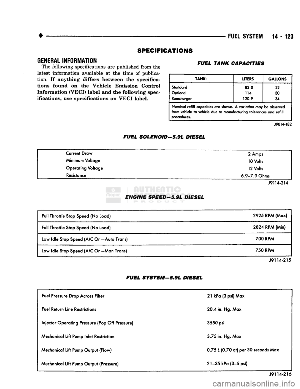
SPECIFICATIONS
GENERAL
INFORMATION
The following specifications
are
published from
the
latest information available
at the
time
of
publica
tion.
If
anything differs between
the
specifica
tions found
on the
Vehicle Emission Control Information (VECI) label
and the
following spec
ifications,
use
specifications
on
VECI label. FUEL TANK CAPACITIES
TANK:
LITERS GALLONS
Standard
83.0 22
Optional 114
30
Ramcharger
120.9
34
Nominal
refill
capacities
are
shown.
A
variation
may be
observed
from vehicle
to
vehicle
due to
manufacturing tolerances
and refill
procedures.
FUEL SOLENOID-5.9L DIESEL
J9014-182
Current Draw
2
Amps
Minimum Voltage 10 Volts
Operating Voltage 12 Volts
Resistance 6.9-7.9 Ohms
J9114-214
ENGINE SPEED—5.9L DIESEL
Full Throttle Stop Speed
(No
Load) 2925 RPM (Max)
Full Throttle Stop Speed
(No
Load)
2824
RPM (Min)
Low Idle Stop Speed (A/C On—Auto Trans) 700 RPM
Low Idle Stop Speed (A/C On—Man Trans) 750 RPM
J9114-215
FUEL SYSTEM—5*9L DIESEL
Fuel Pressure Drop Across Filter 21
kPa
(3 psi) Max
Fuel Return Line Restrictions 20.4 in. Hg. Max
Injector Operating Pressure (Pop
Off
Pressure) 3550
psi
Mechanical Lift Pump Inlet Restriction 3.75 in. Hg. Max
Mechanical Lift Pump Output (Flow) 0.75
L
(0.70 qt)
per 30
seconds Max
Mechanical Lift Pump Output (Pressure) 21-35 kPa (3-5 psi)
J9114-216
Page 1371 of 1502
22 - 2
WHEELS
AND
TIRES
•
METRIC
TIRE
SIZES
P
205 / 75 I 15
J9322-6
Fig.
1
Tire
Size
identification
TIRE
CHAINS
Tire snow chains may be used on certain models.
Refer to Owner's Manual for more information.
CLEANING
OF
TIRES
Steam cleaning may be used for cleaning.
DO NOT use gasoline or wire brush for cleaning.
DO NOT use mineral oil or an oil-based solvent.
PRESSURE GAUGES
High-quality, dial-type, air-pressure gauges are
recommended. After checking with the gauge, re
place valve caps and tighten finger tight.
TIRE
INFLATION
PRESSURES
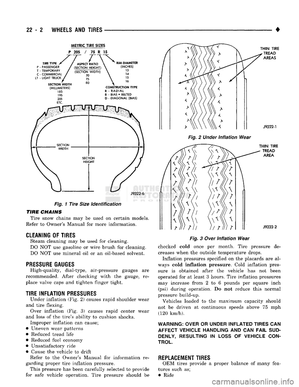
Under inflation (Fig. 2) causes rapid shoulder wear
and tire flexing. Over inflation (Fig. 3) causes rapid center wear
and loss of the tire's ability to cushion shocks. Improper inflation can cause;
• Uneven wear patterns
• Reduced tread life
• Reduced fuel economy
• Unsatisfactory ride
• Cause the vehicle to drift Refer to the Owner's Manual for information re
garding proper tire inflation pressure. This pressure has been carefully selected to provide
for safe vehicle operation. Tire pressure should be
Fig.
2
Under
infiation
Wear
Fig.
3
Over
Infiation
Wear
checked cold once per month. Tire pressure de creases when the outside temperature drops.
Inflation pressures specified on the placards are al
ways cold
inflation
pressure. Cold inflation pres sure is obtained after the vehicle has not been
operated for at least 3 hours. Tire inflation pressures may increase from 2 to 6 pounds per square inch (psi) during operation. Do not reduce this normal
pressure build-up.
Vehicles loaded to the maximum capacity should
not be driven at continuous speeds above 75 mph (120 km/h).
WARNING: OVER
OR
UNDER INFLATED TIRES
CAN
AFFECT VEHICLE HANDLING
AND CAN
FAIL
SUD DENLY, RESULTING
IN
LOSS
OF
VEHICLE CON
TROL
REPLACEMENT TIRES
OEM tires provide a proper balance of many fea
tures such as; • Ride
Page 1395 of 1502
23
- 12
BODY COMPONENTS
•
Fig.
31
Roof
Moulding
REMOVAL
(1) Remove exterior trim as necessary to clear cap
tured edges of the tape stripe being removed
(2) Remove tape stripe using a suitable heat gun
or lamp. This will soften the adhesive backing.
(3) Clean adhesive residue from body finish using
a suitable adhesive remover.
INSTALLATION
INSTALLATION EQUIPMENT
• Bucket filled with a mild dish soap solution.
• Lint free applicator cloth or sponge. • Body putty applicator squeegee.
• Heat gun or sun lamp.
• Razor knife.
The painted surface of the body panel to be covered
by a tape stripe must be smooth and completely cured before the stripe can be applied. If the painted surface is not smooth, wet sand with 600 grit wet/dry
sand paper until surface is smooth.
Ripples and feather edges will read through the
stripe if surface is not properly prepared. (1) With backing still in place, position stripe
across panel to receive the stripe. Apply masking at
top of stripe to hold it in position. (2) Mark outside edge of panel on stripe with
grease pencil. (3) Trim stripe to within 17 mm (0.750 in.) of out
line marks.
(4) Spread stripe across a smooth flat work surface,
stripe side down. (5) Peel paper backing away from stripe exposing
adhesive backing of stripe.
(6) Apply soap solution liberally to adhesive back
ing of stripe. (7) Apply soap solution to body panel surface.
(8) Place stripe into position on body panel.
Smooth out wrinkles by pulling lightly on edges of
tape stripe until it lays flat on panel surface. (9) Push air pockets from under tape stripe to the
perimeter of the panel from the center of the tape stripe out. (10) Remove air bubbles from under tape stripe us
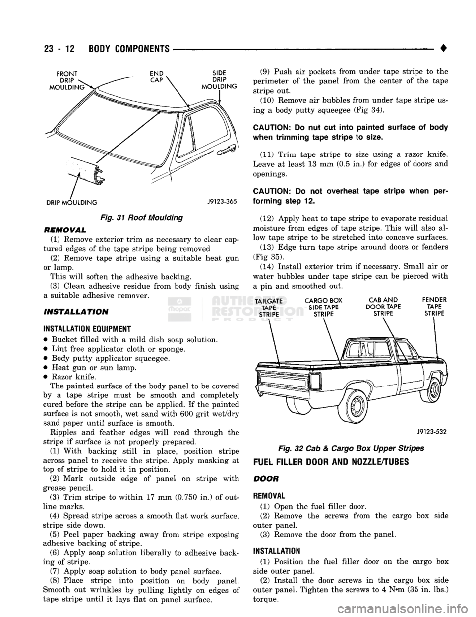
ing a body putty squeegee (Fig 34).
CAUTION:
Do nut cut
Into
painted surface
of body
when trimming
tape
stripe
to
size.
(11) Trim tape stripe to size using a razor knife.
Leave at least 13 mm (0.5 in.) for edges of doors and openings.
CAUTION;
Do not overheat
tape
stripe
when
per
forming
step
12.
(12) Apply heat to tape stripe to evaporate residual
moisture from edges of tape stripe. This will also al
low tape stripe to be stretched into concave surfaces.
(13) Edge turn tape stripe around doors or fenders
(Fig 35). (14) Install exterior trim if necessary. Small air or
water bubbles under tape stripe can be pierced with a pin and smoothed out.
TAILGATE
CARGO BOX
CAB
AND FENDER TAPE SIDE TAPE DOOR TAPE TAPE
STRIPE STRIPE STRIPE STRIPE
J9123-532
Fig.
32 Cab &
Cargo
Box Upper Stripes
FUEL FILLER DOOR AND NOZZLE/TUBES
DOOR
REMOVAL
(1) Open the fuel filler door.
(2) Remove the screws from the cargo box side
outer panel. (3) Remove the door from the panel.
INSTALLATION
(1) Position the fuel filler door on the cargo box
side outer panel.
(2) Install the door screws in the cargo box side
outer panel. Tighten the screws to 4 Nnn (35 in. lbs.)
torque.
Page 1396 of 1502
•
BODY COMPONENTS
23 - 13
AM.
TAPE
STRIPE
WHEELHOUSE
LIP
CARGO BOX
LOWER
REAR,
SIDE PANEL
BUMPER
— •
SECONDARY
COLOR
DOOR
PANEL
FRONT /
FENDER
SCREW
J9123-555
FUEL
FILLER
DOOR
SIDE
OUTER
PANEL
J9123-342
Fig. 33 Cab & Cargo Box Stripes With Two-Tom
Paint
TAPE
STRIPE
FLANGE
J9123-593
Fig. 35
Tape
Stripe installation On Door Flange
(3) Close the fuel filler door. Fig. 36 Fuel Filler Door
NOZZLE/TUBES
REMOVAL
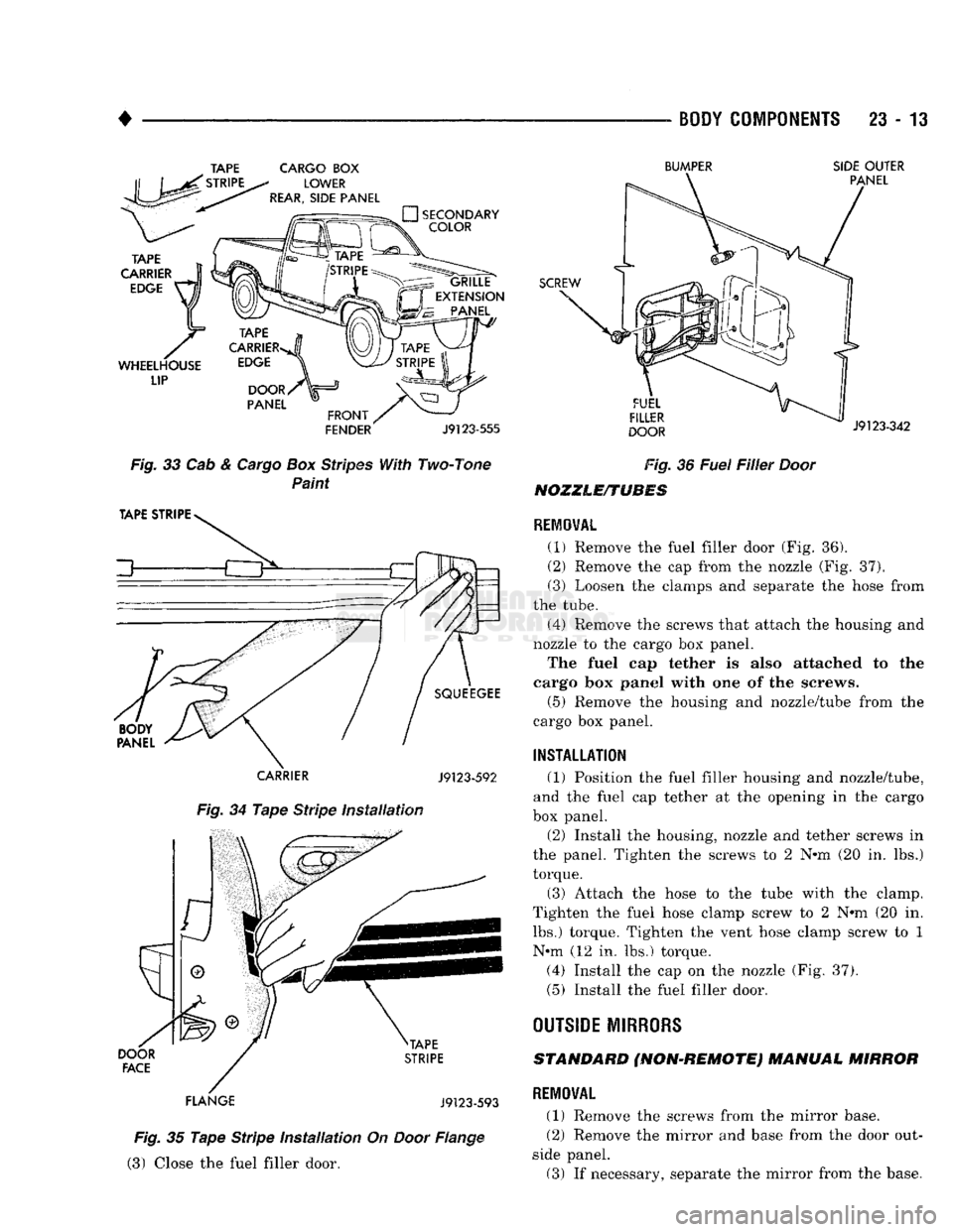
(1) Remove the fuel filler door (Fig. 36).
(2)
Remove the cap from the nozzle (Fig. 37).
(3) Loosen the clamps and separate the hose from
the tube.
(4) Remove the screws that attach the housing and
nozzle to the cargo box panel.
The fuel cap tether is also attached to the
cargo
box panel
with
one of the
screws,
(5) Remove the housing and nozzle/tube from the
cargo box panel.
INSTALLATION
(1) Position the fuel filler housing and nozzle/tube,
and the fuel cap tether at the opening in the cargo
box panel.
(2)
Install the housing, nozzle and tether screws in
the panel. Tighten the screws to 2 N»m (20 in. lbs.)
torque.
(3) Attach the hose to the tube with the clamp.
Tighten the fuel hose clamp screw to 2 N*m (20 in. lbs.) torque. Tighten the vent hose clamp screw to 1 N#m (12 in. lbs.) torque.
(4) Install the cap on the nozzle (Fig. 37),
(5) Install the fuel filler door.
OUTSIDE MIRRORS
STANDARD (NON-REMOTE) MANUAL MIRROR
REMOVAL
(1) Remove the screws from the mirror base.
(2)
Remove the mirror and base from the door out
side panel. (3) If necessary, separate the mirror from the base.