1993 DODGE TRUCK fuel cap
[x] Cancel search: fuel capPage 687 of 1502
9
- 82 5.9L
ENGINE
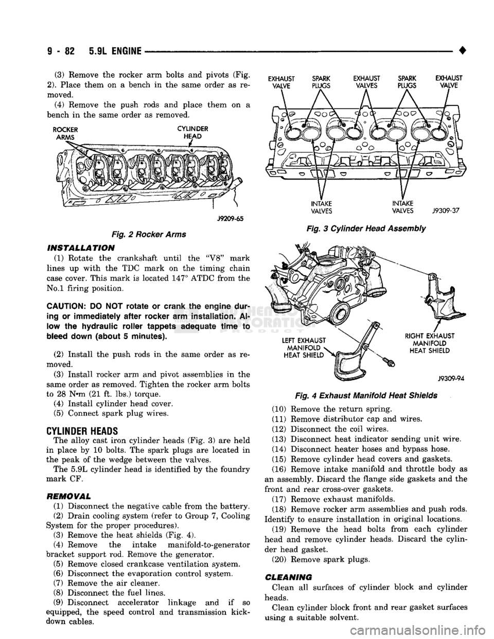
• (3) Remove the rocker arm bolts and pivots (Fig.
2).
Place them on a bench in the same order as re
moved. (4) Remove the push rods and place them on a
bench in the same order as removed.
ROCKER
CYLINDER
J9209-65
Fig.
2
Rocker Arms INSTALLATION
(1) Rotate the crankshaft until the "V8" mark
lines up with the TDC mark on the timing chain
case cover. This mark is located 147° ATDC from the
No.l firing position.
CAUTION:
DO NOT
rotate
or crank the engine dur
ing
or
immediately
after
rocker
arm installation. Al
low the hydraulic roller tappets adequate
time
to
bleed
down
(about 5 minutes).
(2) Install the push rods in the same order as re
moved.
(3) Install rocker arm and pivot assemblies in the
same order as removed. Tighten the rocker arm bolts
to 28 N*m (21 ft. lbs.) torque. (4) Install cylinder head cover.
(5) Connect spark plug wires.
CYLINDER HEADS The alloy cast iron cylinder heads (Fig. 3) are held
in place by 10 bolts. The spark plugs are located in
the peak of the wedge between the valves. The 5.9L cylinder head is identified by the foundry
mark CF.
REMOVAL
(1) Disconnect the negative cable from the battery.
(2) Drain cooling system (refer to Group 7, Cooling
System for the proper procedures).
(3) Remove the heat shields (Fig. 4).
(4) Remove the intake manifold-to-generator
bracket support rod. Remove the generator.
(5) Remove closed crankcase ventilation system. (6) Disconnect the evaporation control system.
(7) Remove the air cleaner.
(8) Disconnect the fuel lines.
(9) Disconnect accelerator linkage and if so
equipped, the speed control and transmission kick- down cables.
EXHAUST SPARK EXHAUST SPARK EXHAUST
VALVE PLUGS VALVES PLUGS VALVE
INTAKE INTAKE
VALVES
VALVES
J9309-37
Fig.
3 Cylinder Head
Assembly
Fig.
4
Exhaust
Manifold Heat
Shields
(10) Remove the return spring.
(11) Remove distributor cap and wires.
(12) Disconnect the coil wires.
(13) Disconnect heat indicator sending unit wire.
(14) Disconnect heater hoses and bypass hose.
(15) Remove cylinder head covers and gaskets.
(16) Remove intake manifold and throttle body as
an assembly. Discard the flange side gaskets and the
front and rear cross-over gaskets.
(17) Remove exhaust manifolds.
(18) Remove rocker arm assemblies and push rods.
Identify to ensure installation in original locations. (19) Remove the head bolts from each cylinder
head and remove cylinder heads. Discard the cylin der head gasket.
(20) Remove spark plugs.
CLEANING
Clean all surfaces of cylinder block and cylinder
heads.
Clean cylinder block front and rear gasket surfaces
using a suitable solvent.
Page 689 of 1502
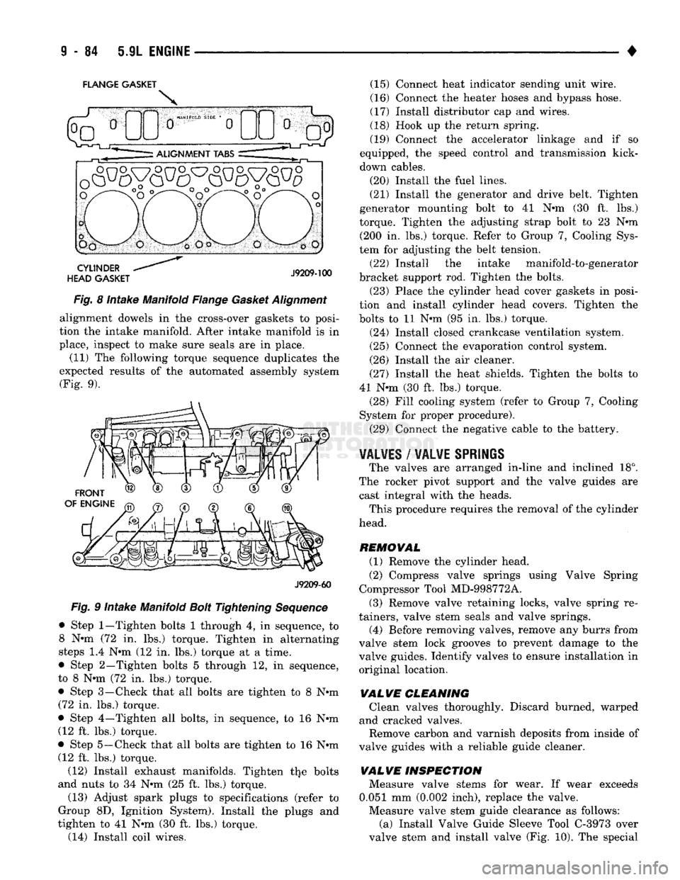
FLANGE GASKET
Fig. 8 Intake Manifold Flange Gasket Alignment alignment dowels in the cross-over gaskets to posi
tion the intake manifold. After intake manifold is in
place, inspect to make sure seals are in place.
(11) The following torque sequence duplicates the
expected results of the automated assembly system (Fig. 9).
J9209-60
Fig. 9 Intake Manifold Bolt Tightening Sequence
• Step
1—Tighten
bolts 1 through 4, in sequence, to 8 N-m (72 in. lbs.) torque. Tighten in alternating
steps 1.4 N-m (12 in. lbs.) torque at a time.
• Step 2—Tighten bolts 5 through 12, in sequence,
to 8 N-m (72 in. lbs.) torque. • Step 3—-Check that all bolts are tighten to 8 N-m
(72 in. lbs.) torque.
• Step 4—Tighten all bolts, in sequence, to 16 N-m (12 ft. lbs.) torque.
• Step 5—Check that all bolts are tighten to 16 N-m (12 ft. lbs.) torque.
(12) Install exhaust manifolds. Tighten the bolts
and nuts to 34 N-m (25 ft. lbs.) torque.
(13) Adjust spark plugs to specifications (refer to
Group 8D, Ignition System). Install the plugs and
tighten to 41 N-m (30 ft. lbs.) torque. (14) Install coil wires. (15) Connect heat indicator sending unit wire.
(16) Connect the heater hoses and bypass hose.
(17) Install distributor cap and wires.
(18) Hook up the return spring.
(19) Connect the accelerator linkage and if so
equipped, the speed control and transmission kick-
down cables.
(20) Install the fuel lines.
(21) Install the generator and drive belt. Tighten
generator mounting bolt to 41 N-m (30 ft. lbs.)
torque. Tighten the adjusting strap bolt to 23 N-m (200 In. lbs.) torque. Refer to Group 7, Cooling Sys
tem for adjusting the belt tension.
(22) Install the intake manifold-to-generator
bracket support rod. Tighten the bolts.
(23) Place the cylinder head cover gaskets in posi
tion and install cylinder head covers. Tighten the
bolts to 11 N-m (95 in. lbs.) torque.
(24) Install closed crankcase ventilation system.
(25) Connect the evaporation control system.
(26) Install the air cleaner.
(27) Install the heat shields. Tighten the bolts to
41 N-m (30 ft. lbs.) torque. (28) Fill cooling system (refer to Group 7, Cooling
System for proper procedure).
(29) Connect the negative cable to the battery.
¥AL¥ES
/
WALWE SPRIliS
The valves are arranged in-line and inclined 18°.
The rocker pivot support and the valve guides are cast integral with the heads. This procedure requires the removal of the cylinder
head.
REMOVAL (1) Remove the cylinder head.
(2) Compress valve springs using Valve Spring
Compressor Tool MD-998772A.
(3) Remove valve retaining locks, valve spring re
tainers, valve stem seals and valve springs.
(4) Before removing valves, remove any burrs from
valve stem lock grooves to prevent damage to the
valve guides. Identify valves to ensure Installation in original location,
VALVE
CLEANING Clean valves thoroughly. Discard burned, warped
and cracked valves.
Remove carbon and varnish deposits from Inside of
valve guides with a reliable guide cleaner.
VALVE
INSPECTION Measure valve stems for wear. If wear exceeds
0.051 mm (0.002 Inch), replace the valve.
Measure valve stem guide clearance as follows: (a) Install Valve Guide Sleeve Tool C-3973 over
valve stem and install valve (Fig. 10). The special
Page 712 of 1502
•
5.9L
(DIESEL)
ENGINE
9 -
107
5.9L
(DIESEL)
ENGINE
SERVICE
PROCEDURES
INDEX
page
Camshaft
127
Crankshaft
138
Cylinder
Block
129
Cylinder
Head
113
Engine
Assembly
. 109
Engine
Front
Mounts
(Insulators
/
Brackets)
... 107
Engine
Rear Support
108
Gear
Housing
/
Cover
122
General
Information
107
Oil Cooler Element
/
Gasket
. 149
Oil
Filter
148
page
Oil
Filter
Bypass
Valve
. 148
Oil Pan
/
Suction Tube
146
Oil Pressure Regulator Valve
/
Spring
148
Oil Pump
146
Piston
/
Connecting
Rod
Assembly
134
Rocker
Levers
/
Push
Rods
112
Specifications—5.9L Diesel Engines
151
Tappet
125
Timing
Pin
123
Valve Clearance
Adjustment
...............
121
Valves
and
Valve Springs
116
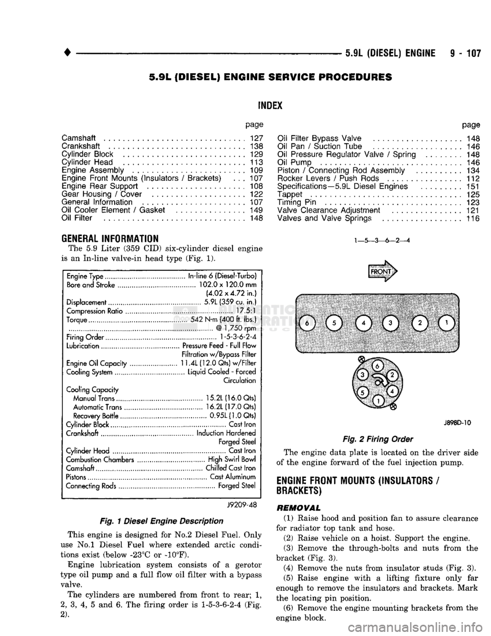
GENERAL INFORMATION The
5.9
Liter
(359 CID)
six-cylinder diesel engine
is
an
In-line valve-in head type
(Fig. 1).
Fig.
1
Diesel
Engine
Description
This engine
is
designed
for No.2
Diesel Fuel. Only
use
No.l
Diesel Fuel where extended arctic condi
tions exist (below -23°C
or -10°F).
Engine lubrication system consists
of a
gerotor
type
oil
pump
and a
full flow
oil
filter with
a
bypass valve.
The cylinders
are
numbered from front
to
rear;
1,
2,
3, 4, 5 and 6. The
firing order
is
1-5-3-6-2-4
(Fig.
2).
J898D-10
Fig.
2
Firing Order
The engine data plate
is
located
on the
driver side
of
the
engine forward
of the
fuel injection pump.
ENGINE FRONT MOUNTS (INSULATORS
/
BRACKETS)
REMOVAL (1) Raise hood
and
position
fan to
assure clearance
for radiator
top
tank
and
hose.
(2) Raise vehicle
on a
hoist. Support
the
engine.
(3) Remove
the
through-bolts
and
nuts from
the
bracket
(Fig. 3).
(4) Remove
the
nuts from insulator studs
(Fig. 3).
(5) Raise engine with
a
lifting fixture only
far
enough
to
remove
the
insulators
and
brackets. Mark
the locating
pin
position.
(6) Remove
the
engine mounting brackets from
the
engine block.
Engine Type
In-line
6
(Diesel-Turbo)
Bore and Stroke 102.0 x 120.0 mm
(4.02x4.72 in.)
Displacement 5.9L (359 cu.
in.)
Compression Ratio 17.5:1
Torque 542 N-m (400 ft. lbs.)
@
1,750 rpm
Firing Order
1-5-3-6-2-4
Lubrication Pressure Feed - Full Flow
Filtration w/Bypass Filter
Engine Oil Capacity
11.4L
(12.0 Qts) w/Filter
Cooling System Liquid Cooled
-
Forced
Circulation
Cooling Capacity
Manual Trans 15.2L (16.0 Qts)
Automatic Trans 16.2L (17.0 Qts)
Recovery Bottle 0.95L(1.0Qts)
Cylinder Block.... Cast Iron
Crankshaft Induction Hardened
Forged Steel
Cylinder Head Cast Iron
Combustion Chambers High Swirl Bowl
Camshaft.... Chilled Cast Iron
Pistons Cast Aluminum
Connecting Rods Forged Steel
J9209-48
Page 751 of 1502
9
- 148 5.9L
(DIESEL) ENGINE
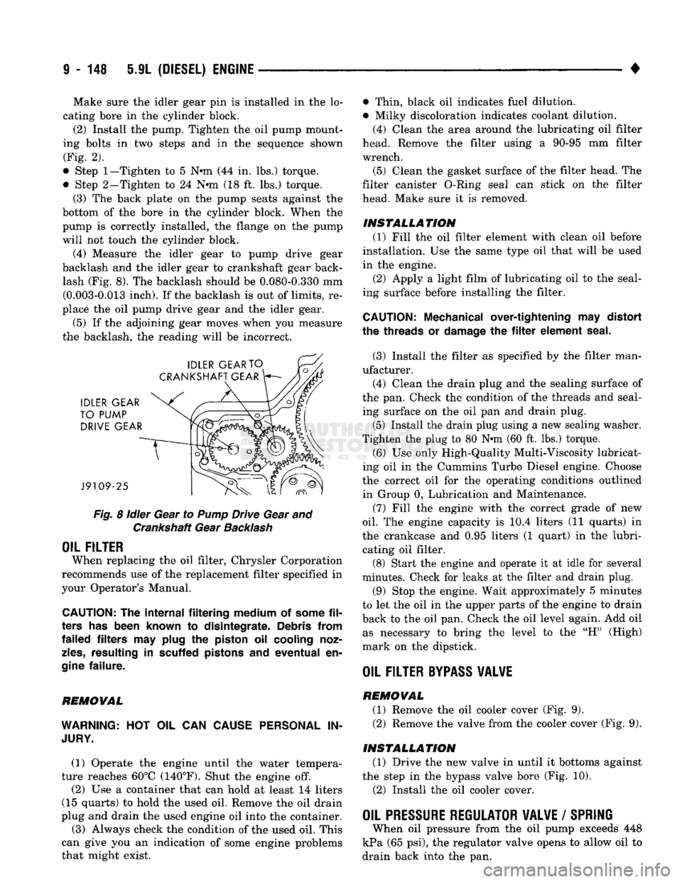
• Make sure the idler gear pin is installed in the lo
cating bore in the cylinder block. (2) Install the pump. Tighten the oil pump mount
ing bolts in two steps and in the sequence shown (Fig. 2).
• Step
1—Tighten
to 5 N«m (44 in. lbs.) torque.
• Step 2-Tighten to 24 N*m (18 ft. lbs.) torque. (3) The back plate on the pump seats against the
bottom of the bore in the cylinder block. When the
pump is correctly installed, the flange on the pump will not touch the cylinder block.
(4) Measure the idler gear to pump drive gear
backlash and the idler gear to crankshaft gear back lash (Fig. 8). The backlash should be 0.080-0.330 mm (0.003-0.013 inch). If the backlash is out of limits, re
place the oil pump drive gear and the idler gear.
(5) If the adjoining gear moves when you measure
the backlash, the reading will be incorrect.
Fig.
8
idler
Gear to
Pump
Drive Gear and Crankshaft Gear
Backlash
OIL FILTER
When replacing the oil filter, Chrysler Corporation
recommends use of the replacement filter specified in
your Operator's Manual.
CAUTION:
The
internal filtering medium
of
some
fil
ters
has
been known
to
disintegrate. Debris from
failed filters
may
plug
the
piston
oil
cooling noz
zles,
resulting
in
scuffed pistons
and
eventual
en
gine
failure.
REMOVAL
WARNING:
HOT OIL CAN
CAUSE PERSONAL
IN
JURY.
(1) Operate the engine until the water tempera
ture reaches 60°C (140°F). Shut the engine off.
(2) Use a container that can hold at least 14 liters
(15 quarts) to hold the used oil. Remove the oil drain
plug and drain the used engine oil into the container.
(3) Always check the condition of the used oil. This
can give you an indication of some engine problems
that might exist. • Thin, black oil indicates fuel dilution.
• Milky discoloration indicates coolant dilution.
(4) Clean the area around the lubricating oil filter
head. Remove the filter using a 90-95 mm filter
wrench.
(5) Clean the gasket surface of the filter head. The
filter canister O-Ring seal can stick on the filter
head. Make sure it is removed.
INSTALLATION (1) Fill the oil filter element with clean oil before
installation. Use the same type oil that will be used
in the engine.
(2) Apply a light film of lubricating oil to the seal
ing surface before installing the filter.
CAUTION:
Mechanical over-tightening
may
distort
the threads
or
damage
the filter
element seal.
(3) Install the filter as specified by the filter man
ufacturer. (4) Clean the drain plug and the sealing surface of
the pan. Check the condition of the threads and seal ing surface on the oil pan and drain plug.
(5) Install the drain plug using a new sealing washer.
Tighten the plug to 80 N-m (60 ft. lbs.) torque.
(6) Use only High-Quality Multi-Viscosity lubricat
ing oil in the Cummins Turbo Diesel engine. Choose
the correct oil for the operating conditions outlined in Group 0, Lubrication and Maintenance.
(7) Fill the enginfe with the correct grade of new
oil.
The engine capacity is i0.4 liters (11 quarts) in
the crankcase and 0.95 liters (1 quart) in the lubri cating oil filter. (8) Start the engine and operate it at idle for several
minutes. Check for leaks at the filter and drain plug.
(9) Stop the engine. Wait approximately 5 minutes
to let the oil in the upper parts of the engine to drain
back to the oil pan. Check the oil level again. Add oil as necessary to bring the level to the "H" (High)
mark on the dipstick.
OIL FILTER
BYPASS
VALWE
REMOVAL
(1) Remove the oil cooler cover (Fig. 9). (2) Remove the valve from the cooler cover (Fig. 9).
INSTALLATION (1) Drive the new valve in until it bottoms against
the step in the bypass valve bore (Fig. 10).
(2) Install the oil cooler cover.
OIL PRESSURE REGULATOR VALVE
/
SPRING
When oil pressure from the oil pump exceeds 448
kPa (65 psi), the regulator valve opens to allow oil to
drain back into the pan.
Page 756 of 1502
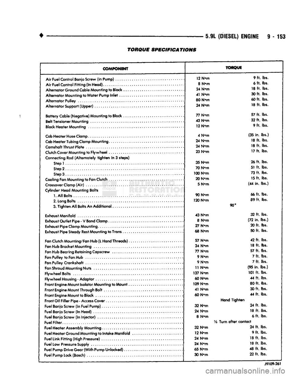
5.9L
(DIESEL)
ENGINE
9-153
TORQUE
SPECIFICATIONS
COMPONENT
Air
Fuel
Control
Banjo Screw (In Pump) ....
Air
Fuel
Control
Fitting
(In
Head)
Alternator
Ground Cable Mounting to
Block
Alternator
Mounting to
Water
Pump
Inlet
..
Alternator
Pulley
Alternator
Support
(Upper)
Battery
Cable
(Negative)
Mounting to Block ,
Belt
Tensioner
Mounting
Block
Heater
Mounting
Cab
Heater
Hose
Clamp
Cab
Heater
Tubing
Clamp Mounting.......
Camshaft
Thrust
Plate
Clutch Cover Mounting to
Flywheel
...
Connecting Rod
(Alternately
tighten
in 3 steps) Step 1
Step 2
Step 3 .
Cooling Fan Mounting to
Fan
Clutch
Crossover
Clamp (Air)
Cylinder
Head
Mounting Bolts
1.
All
Bolts....
2.
Long
Bolts
.........
3.
Tighten
All
Bolts
An
Additional
Exhaust
Manifold
Exhaust
Outlet
Pipe
- V
Band
Clamp
Exhaust
Pipe
Clamp Mounting
Exhaust
Pipe
Steady
Rest
Mounting to Trans .
Fan
Clutch Mounting/Fan Hub
(L
Hand
Threads)..
Fan Hub
Bracket
Mounting
Fan Hub Bearing
Retaining
Capscrew
Fan
Pulley
to
Fan
Hub
Fan
Pulley
Crankshaft .
Fan
Shroud
Mounting Nuts
Flywheel
Bolts
Flywheel
Housing
- Adaptor
Front
Engine
Mount Isolator Mounting to Mount..
Front
Engine
Mount Through Bolt
Front
Engine
Mount to Block
Front
Oil
Filler
Pipe
-
Access
Cover
Fuel
Banjo Screw (In
Fuel
Pump)
Fuel
Banjo Screw (In
Head)
Fuel
Banjo Screw (In
Injector)
Fuel
Filter
Fuel
Heater
Assembly
Mounting
Fuel
Heater
Ground Mounting to
Intake
Manifold
Fuel
Link
Fitting
(High Pressure)
Fuel
Low Pressure Supply
Fuel
Pump
Drive
Gear
(With
Pump
Unlocked)
Fuel
Pump Lock (Bosch)
TORQUE
12 N-m 9 ft. lbs.
8 N-m 6 ft. lbs.
24 N-m 18 ft. lbs.
41 N*m 30 ft. lbs.
80 N-m 60 ft. lbs.
24 N-m 18 ft. lbs.
77 N-m 57 ft. lbs.
43 N-m 32 ft. lbs.
12 N-m 9 ft. lbs.
4 N-m (35 in. lbs.)
24 N-m 18 ft. lbs.
24 N-m 18 ft. lbs.
23 N-m 17 ft. lbs.
35 N-m 26 ft. lbs.
70 N-m 51 ft. lbs.
100 N-m 73 ft. lbs.
20 N-m 15 ft. lbs.
5
N-m (44 in. lbs.)
90 N-m 66 ft. lbs.
120 N-m 89 ft. lbs.
90°
43 N-m 32 ft. lbs.
8 N-m (72 in. lbs.)
27 N-m 20 ft. lbs.
68 N-m 50 ft. lbs.
57 N-m 42 ft. lbs.
24 N-m 18 ft. lbs.
77 N-m 57 ft. lbs.
9 N-m 7 ft. lbs.
9 N-m 7 ft. lbs.
11 N-m (95 in. lbs.)
137 N-m 101 ft. lbs.
60 N-m 44 ft. lbs.
109 N-m 80 ft. lbs.
41 N-m 30 ft. lbs.
60 N-m 44 ft. lbs.
Hand
Tighten
32 N-m 24 ft. lbs.
24 N-m 18 ft. lbs.
8 N-m 6 ft. lbs.
Vi
Turn
after
contact
32 N-m 24 ft. lbs.
12 N-m 9 ft. lbs.
24 N-m 18 ft. lbs.
24 N-m 18 ft. lbs.
65 N-m 48 ft. lbs.
30 N-m 22 ft. lbs.
J9109-261
Page 757 of 1502
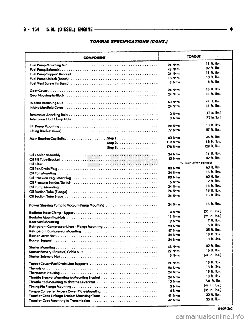
9
- 154 5.9L
(DIESEL)
ENGINE
TORQUE
SPECIFICATIONS
(CONT.J
COMPONENT
TORQUE
Fuel
Pump
Mounting
Nut
..
Fuel
Pump
Solenoid
Fuel
Pump
Support
Bracket
Fuel
Pump
Unlock
(Bosch)
.
Fuel
Vent
Screw
(In Banjo)
.
Gear
Cover
Gear
Housing-to-Block
Injector
Retaining Nut.
Intake
Manifold
Cover
Intercooler
Attaching
Bolts
•
•
Intercooler
Duct
Clamp
Nuts.
Lift
Pump
Mounting
Lifting Bracket (Rear)
..
Main
Bearing
Cap
Bolts.
Step!.
Step
2.
Steo3.
Oil
Cooler
Assembly
Oil
Fill
Tube Bracket
Oil
Filter
Oil
Pan
Drain
Plug
Oil
Pan
Mounting.........
Oil
Pressure
Regulator
Plug
Oil
Pressure
Sender/Switch
Oil
Pump
Mounting
Oil
Suction
Tube (Flange)
..
Oil
Suction
Tube
Brace
Power Steering
Pump
to
Vacuum
Pump
Mounting
Radiator Hose Clamp
-
Upper
Radiator Mounting Nuts Rear Seal Mounting
Refrigerant
Compressor
Lines
-
Flange Mounting
Refrigerant
Compressor
Mounting
Rocker Lever Nut
Rocker Support
Starter
Mounting
Starter
Battery
(Positive) Cable Nut
Starter
Solenoid Nut
Tappet
Cover/Fuel Drain Line Supports
Thermistor
,
Thermostat Housing
Throttle
Bracket Mounting to Mounting Bracket.
Throttle
Rod
Mounting to
Throttle
Lever Nut
...
Timing Pin Flange Mounting
Torque Converter
Access
Cover
Plate
Mounting
Transfer
Case
Linkage Bracket Mounting/Trans Transfer
Case
Mounting to
Transmission
..
24
N-m
18
ft.
lbs.
43
N-m
32 ft. lbs.
24
N-m
18
ft.
lbs.
13
N-m
10
ft. lbs.
8
N-m
6 ft. lbs.
24
N-m
18
ft.
lbs.
24
N-m
18
ft.
lbs.
60
N-m
44
ft.
lbs.
24
N-m
18
ft.
lbs.
2
N-m
(17
in.
lbs.)
8
N-m
(72
in.
lbs.)
24
N-m
18
ft.
lbs.
77
N-m
57
ft.
lbs.
60 N-m 45 ft. lbs.
119
N-m
88
ft.
lbs.
176 N-m 129
ft.
lbs.
24
N-m
18
ft.
lbs.
43
N-m
32
ft.
lbs.
Turn
after
contact
80 N-m 60 ft. lbs.
24
N-m
18
ft.
lbs.
80 N-m 60 ft. lbs.
16
N-m
12 ft. lbs.
24
N-m
18
ft.
lbs.
24
N-m
18
ft.
lbs.
24
N-m
18
ft.
lbs.
24
N-m
18
ft.
lbs.
4
N-m
(35 in. lbs.)
11
N-m
(95 in. lbs.)
9 N-m 7
ft.
lbs.
20
N-m
15
ft.
lbs.
47
N-m
35 ft. lbs.
24
N-m
18
ft.
lbs.
24
N-m
18
ft.
lbs.
43
N-m
32
ft.
lbs.
22
N-m
16
ft. lbs.
5
N-m
(44 in. lbs.)
24
N-m
18
ft.
lbs.
24
N-m
18
ft.
lbs.
24
N-m
18
ft.
lbs.
24
N-m
18
ft.
lbs.
10 N-m
73
ft.
lbs.
5
N-m
(44 in. lbs.)
4
N-m
(35
in. lbs.)
41
N-m
30 ft. lbs.
47
N-m
35 ft. lbs.
J9109-262
Page 772 of 1502
•
EXHAUST SYSTEM
AND
INTAKE MANIFOLD
11-13
TIGHTENING
TORQUE
23
N-m
(200
IN. LBS.)
7
N-m
(65
IN. LBS.)
5 N-m
(40
IN. LBS.)
HEAT
SHIELD CATALYTIC
CONVERTER
LOWER HEAT SHIELD HEAT
SHIELD UPPER
HEAT
SHIELD
CROSSMEMBER
SKID
PLATE
UPPER HEAT SHIELD
(6 IN.
RAIL) CONED WASHER
UPPER HEAT SHIELD
(7 IN.
RAIL)
J9211-21
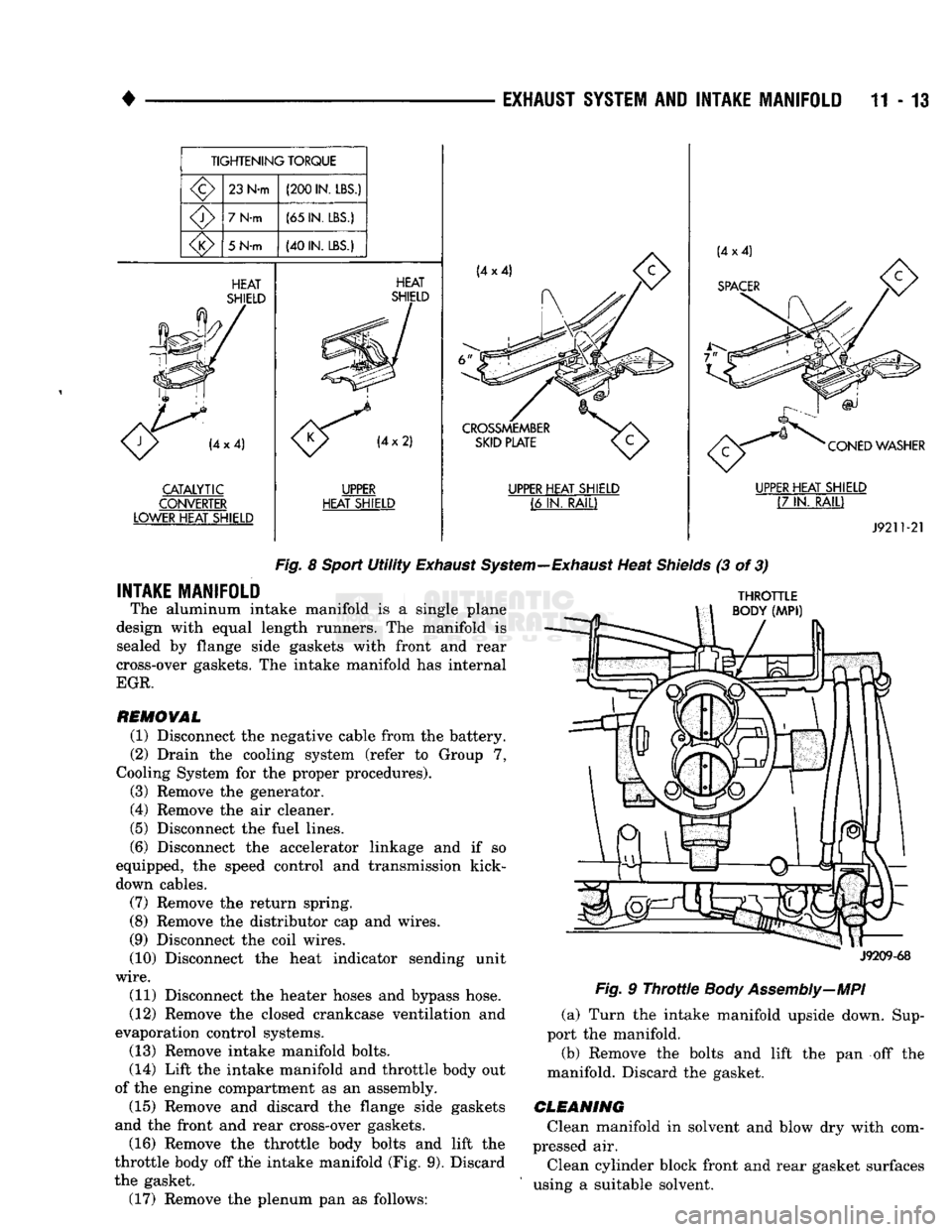
Fig.
8
Sport
Utility
Exhaust
System—Exhaust
Heat
Shields
(3 of 3)
INTAKE MANIFOLD
The aluminum intake manifold is a single plane
design with equal length runners. The manifold is sealed by flange side gaskets with front and rear
cross-over gaskets. The intake manifold has internal
EGR.
REMOVAL
(1) Disconnect the negative cable from the battery.
(2) Drain the cooling system (refer to Group 7,
Cooling System for the proper procedures).
(3) Remove the generator.
(4) Remove the air cleaner.
(5) Disconnect the fuel lines.
(6) Disconnect the accelerator linkage and if so
equipped, the speed control and transmission kick-
down cables.
(7) Remove the return spring.
(8) Remove the distributor cap and wires.
(9) Disconnect the coil wires.
(10) Disconnect the heat indicator sending unit
wire.
(11) Disconnect the heater hoses and bypass hose.
(12) Remove the closed crankcase ventilation and
evaporation control systems. (13) Remove intake manifold bolts.
(14) Lift the intake manifold and throttle body out
of the engine compartment as an assembly. (15) Remove and discard the flange side gaskets
and the front and rear cross-over gaskets.
(16) Remove the throttle body bolts and lift the
throttle body off the intake manifold (Fig. 9). Discard
the gasket. (17) Remove the plenum pan as follows:
THROTTLE
BODY
(MPI)
J9209-68
Fig.
9
Throttle
Body Assembly—MPI
(a) Turn the intake manifold upside down. Sup
port the manifold.
(b) Remove the bolts and lift the pan off the
manifold. Discard the gasket.
CLEANING
Clean manifold in solvent and blow dry with com
pressed air.
Clean cylinder block front and rear gasket surfaces
using a suitable solvent.
Page 774 of 1502
EXHAUST SYSTEM
AND
INTAKE MANIFOLD
11-15
FLANGE GASKET
o
o
CYLINDER
HEAD GASKET
J9209-101
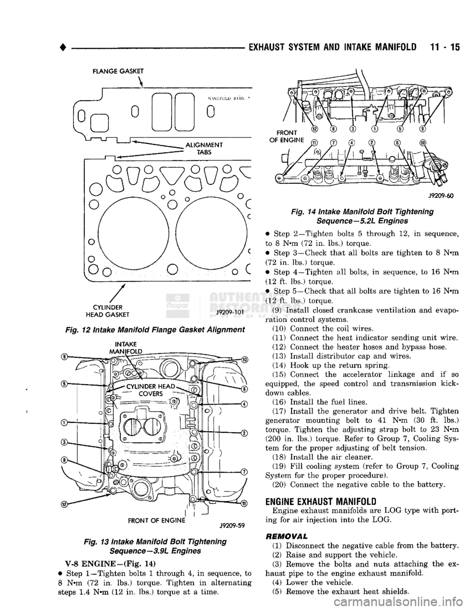
Fig. 12 Intake Manifold Flange Gasket Alignment
®— INTAKE
MANIFOLD
FRONT OF
ENGINE
J9209-59
Fig. 13 Intake Manifold Bolt Tightening Sequence—3.9L Engines
V-8 ENGINE—(Fig* 14)
• Step
1—Tighten
bolts 1 through 4, in sequence, to 8 Nun (72 in. lbs.) torque. Tighten in alternating
steps 1.4 Nun (12 in. lbs.) torque at a time.
FRONT
OF ENGINE
J9209-60
Fig. 14 Intake Manifold Bolt Tightening Sequence—5.2L Engines
• Step 2—Tighten bolts 5 through 12, in sequence,
to 8 Nun (72 in. lbs.) torque. • Step 3—Check that all bolts are tighten to 8 Nun (72 in. lbs.) torque.
• Step 4—Tighten all bolts, in sequence, to 16 Nun (12 ft. lbs.) torque.
• Step 5—Check that all bolts are tighten to 16 Nun (12 ft. lbs.) torque.
(9) Install closed crankcase ventilation and evapo
ration control systems. (10) Connect the coil wires.
(11) Connect the heat indicator sending unit wire.
(12) Connect the heater hoses and bypass hose.
(13) Install distributor cap and wires.
(14) Hook up the return spring.
(15) Connect the accelerator linkage and if so
equipped, the speed control and transmission kick-
down cables. (16) Install the fuel lines,
(17) Install the generator and drive belt. Tighten
generator mounting bolt to 41 Nun (30 ft. lbs.)
torque. Tighten the adjusting strap bolt to 23 Nun (200 in. lbs.) torque. Refer to Group 7, Cooling Sys
tem for the proper adjusting of belt tension. (18) Install the air cleaner. (19) Fill cooling system (refer to Group 7, Cooling
System for the proper procedure). (20) Connect the negative cable to the battery.
ENGINE EXHAUST MANIFOLD
Engine exhaust manifolds are LOG type with port
ing for air injection into the LOG.
REMOVAL (1) Disconnect the negative cable from the battery.
(2) Raise and support the vehicle.
(3) Remove the bolts and nuts attaching the ex
haust pipe to the engine exhaust manifold. (4) Lower the vehicle. (5) Remove the exhaust heat shields.