1993 DODGE TRUCK fuel cap
[x] Cancel search: fuel capPage 363 of 1502
8D
- 12
IGNITION
SYSTEMS
•
XX
oooooooooo
,0000000000
\2141
3%
lOOOOOOOOOO
OOOOOOOOOO
si
20
fcji^OQOOOOOOJ
«r
~
• • -
•
- - #
•oooooooooo.
CONNECTOR
TERMINAL
SIDE
SHOWN
J908D-42
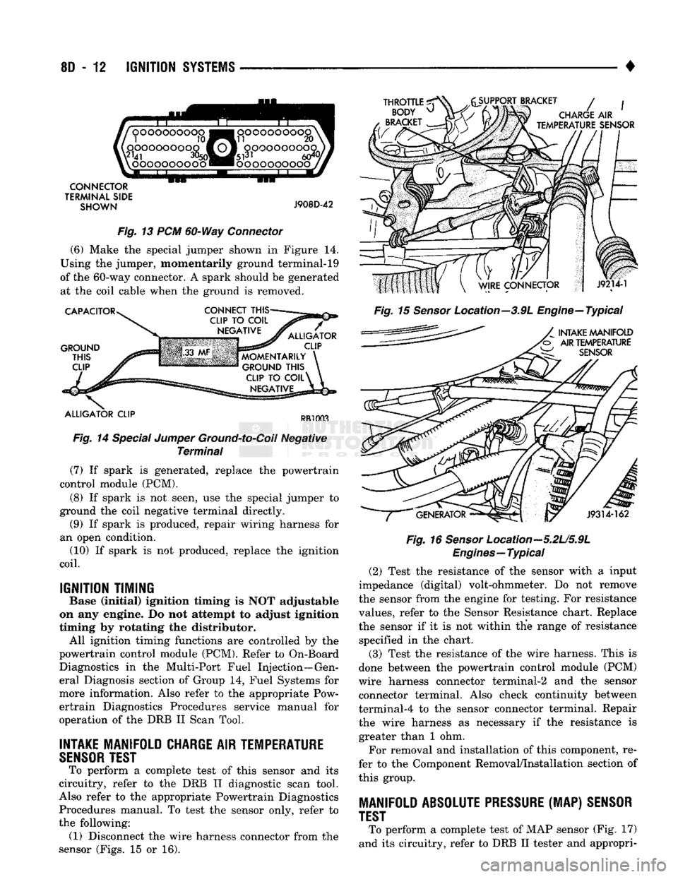
Fig. 13 PCM 60-Way Connector
(6) Make the special jumper shown in Figure 14.
Using the jumper, momentarily ground terminal-19
of the 60-way connector. A spark should be generated at the coil cable when the ground is removed.
CAPACITOR
GROUND
THIS
CLIP
CONNECT
THIS-
ALLIGATOR
CLIP
MOMENTARILY
GROUND
THIS
CLIP
TO
COIL^
NEGATIVE
ALLIGATOR
CLIP
PR1003
Fig. 14 Special Jumper Ground-to-Coil Negative Terminal (7) If spark is generated, replace the powertrain
control module (PCM).
(8) If spark is not seen, use the special jumper to
ground the coil negative terminal directly. (9) If spark is produced, repair wiring harness for
an open condition. (10) If spark is not produced, replace the ignition
coil.
IGNITION TIMING
Base (Initial) ignition timing Is NOT adjustable
on any engine. Do not attempt to adjust Ignition
timing by rotating the distributor. All ignition timing functions are controlled by the
powertrain control module (PCM). Refer to On-Board Diagnostics in the Multi-Port Fuel Injection—Gen
eral Diagnosis section of Group 14, Fuel Systems for
more information. Also refer to the appropriate Pow ertrain Diagnostics Procedures service manual for
operation of the DRB II Scan Tool.
INTAKE
MANIFOLD
CHARGE
AIR
TEMPERATURE
SENSOR
TEST
To perform a complete test of this sensor and its
circuitry, refer to the DRB II diagnostic scan tool.
Also refer to the appropriate Powertrain Diagnostics Procedures manual. To test the sensor only, refer to
the following: (1) Disconnect the wire harness connector from the
sensor (Figs. 15 or 16).
THROTTLE
^
BODY
^
BRACKET
SUPPORT BRACKET
/
CHARGE
AIR
TEMPERATURE
SENSOR
Fig. 15 Sensor Location--3.9L Engine—Typical
INTAKE
MANIFOLD
AIR
TEMPERATURE
W
SENSOR
J9314-162
Fig. 16
Sensor
Location—5.2U5.9L
Engines—Typical
(2) Test the resistance of the sensor with a input
impedance (digital) volt-ohmmeter. Do not remove
the sensor from the engine for testing. For resistance
values, refer to the Sensor Resistance chart. Replace
the sensor if it is not within the range of resistance specified in the chart.
(3) Test the resistance of the wire harness. This is
done between the powertrain control module (PCM)
wire harness connector terminal-2 and the sensor connector terminal. Also check continuity between
terminal-4 to the sensor connector terminal. Repair
the wire harness as necessary if the resistance is greater than 1 ohm.
For removal and installation of this component, re
fer to the Component Removal/Installation section of
this group.
MANIFOLD
ABSOLUTE PRESSURE
(MAP)
SENSOR
TEST
To perform a complete test of MAP sensor (Fig. 17)
and its circuitry, refer to DRB II tester and appropri-
Page 368 of 1502
•
IGNITION SYSTEMS
80-17
or punctured, there will
be a
noticeable spark jump
from
the
damaged area
to the
test probe.
The
cable
running from
the
ignition coil
to the
distributor
cap
can
be
checked
in the
same manner. Cracked, dam aged
or
faulty cables should
be
replaced with resis
tance type cable. This
can be
identified
by the
words ELECTRONIC SUPPRESSION printed
on the
cable
jacket.
Use
an
ohmmeter
to
test
for
open circuits, exces
sive resistance
or
loose terminals. Remove
the
dis
tributor
cap
from
the
distributor.
Do not
remove cables from
cap.
Remove cable from spark plug.
Connect ohmmeter
to
spark plug terminal
end of ca
ble
and to
corresponding electrode
in
distributor
cap.
Resistance should
be 250 to 1000
Ohms
per
inch
of
cable.
If not,
remove cable from distributor
cap
tower and connect ohmmeter
to the
terminal ends
of
cable.
If resistance
is not
within specifications
as
found
in
the Spark Plug Cable Resistance chart, replace
the
cable. Test
all
spark plug cables
in
this manner.
SPARK
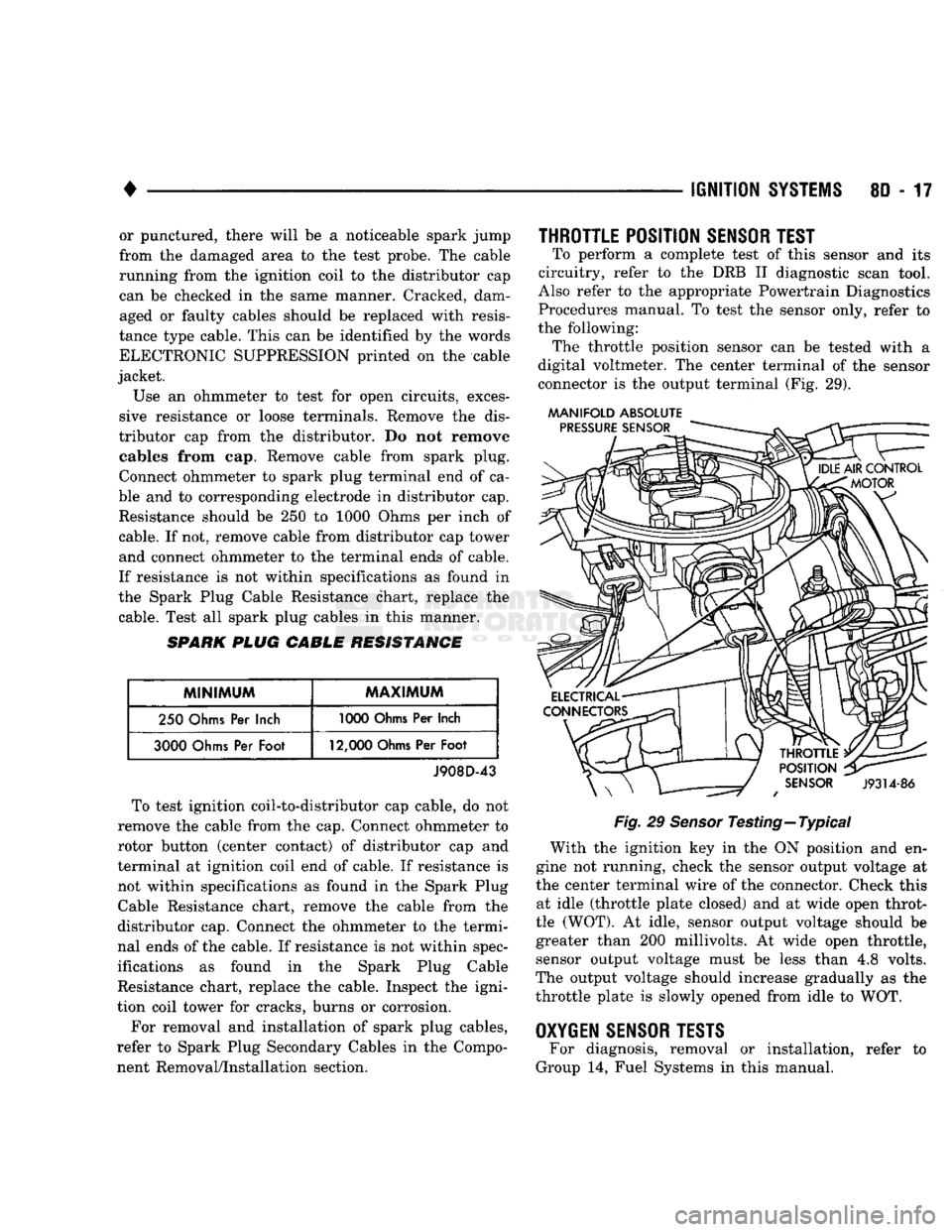
PLUG CABLE RESISTANCE
MINIMUM
MAXIMUM
250
Ohms
Per
Inch
1000
Ohms
Per
Inch
3000
Ohms
Per
Foot
12,000
Ohms
Per
Foot
J908D-43 To test ignition coil-to-distributor
cap
cable,
do not
remove
the
cable from
the cap.
Connect ohmmeter
to
rotor button (center contact)
of
distributor
cap and
terminal
at
ignition coil
end of
cable.
If
resistance
is
not within specifications
as
found
in the
Spark Plug
Cable Resistance chart, remove
the
cable from
the
distributor
cap.
Connect
the
ohmmeter
to the
termi
nal ends
of the
cable.
If
resistance
is not
within spec
ifications
as
found
in the
Spark Plug Cable
Resistance chart, replace
the
cable. Inspect
the
igni
tion coil tower
for
cracks, burns
or
corrosion.
For removal
and
installation
of
spark plug cables,
refer
to
Spark Plug Secondary Cables
in the
Compo nent Removal/Installation section.
THROTTLE POSITION
SENSOR
TEST
To perform
a
complete test
of
this sensor
and its
circuitry, refer
to the DRB II
diagnostic scan tool.
Also refer
to the
appropriate Powertrain Diagnostics
Procedures manual.
To
test
the
sensor only, refer
to
the following: The throttle position sensor
can be
tested with
a
digital voltmeter.
The
center terminal
of the
sensor
connector
is the
output terminal
(Fig. 29).
MANIFOLD ABSOLUTE
Fig.
29
Sensor
Testing—Typical With
the
ignition
key in the ON
position
and en
gine
not
running, check
the
sensor output voltage
at
the center terminal wire
of the
connector. Check this at idle (throttle plate closed)
and at
wide open throt
tle (WOT).
At
idle, sensor output voltage should
be
greater than
200
millivolts.
At
wide open throttle, sensor output voltage must
be
less than
4,8
volts.
The output voltage should increase gradually
as the
throttle plate
is
slowly opened from idle
to WOT.
OXYGEN
SENSOR
TESTS
For diagnosis, removal
or
installation, refer
to
Group
14,
Fuel Systems
in
this manual.
Page 369 of 1502
8D
- 18
IGNITION
SYSTEMS
•
COMPONENT REMGWAL/INSTALLATION
INDEX
page
Automatic
Shut Down (ASD) Relay
18
Camshaft
Position
Sensor
, 18
Crankshaft Position
Sensor
18
Distributor
Service
20
Engine
Coolant Temperature
Sensor
20
General
Information
18
Ignition
Coil
21
page
Intake
Manifold Charge
Air
Temperature
Sensor
. 22
Manifold Absolute Pressure (MAP)
Sensor
..... 22
Oxygen
(02)
Sensor
22
Powertrain
Control
Module (PCM)
22
Spark
Plug Secondary Cables
24
Spark
Plugs
23
Throttle
Position
Sensor
(TPS)
24
GENERAL
INFORMATION
This section
of the
group, Component Removal/In
stallation, will discuss
the
removal
and
installation
of ignition system components. For basic ignition system diagnostics
and
service
adjustments, refer
to the
Diagnostics/Service Proce
dures section
of
this group. For system operation
and
component identification,
refer
to the
Component Identification/System Opera
tion section
of
this group.
AUTOMATIC
SHUT DOWN
(ASb)
RELAY
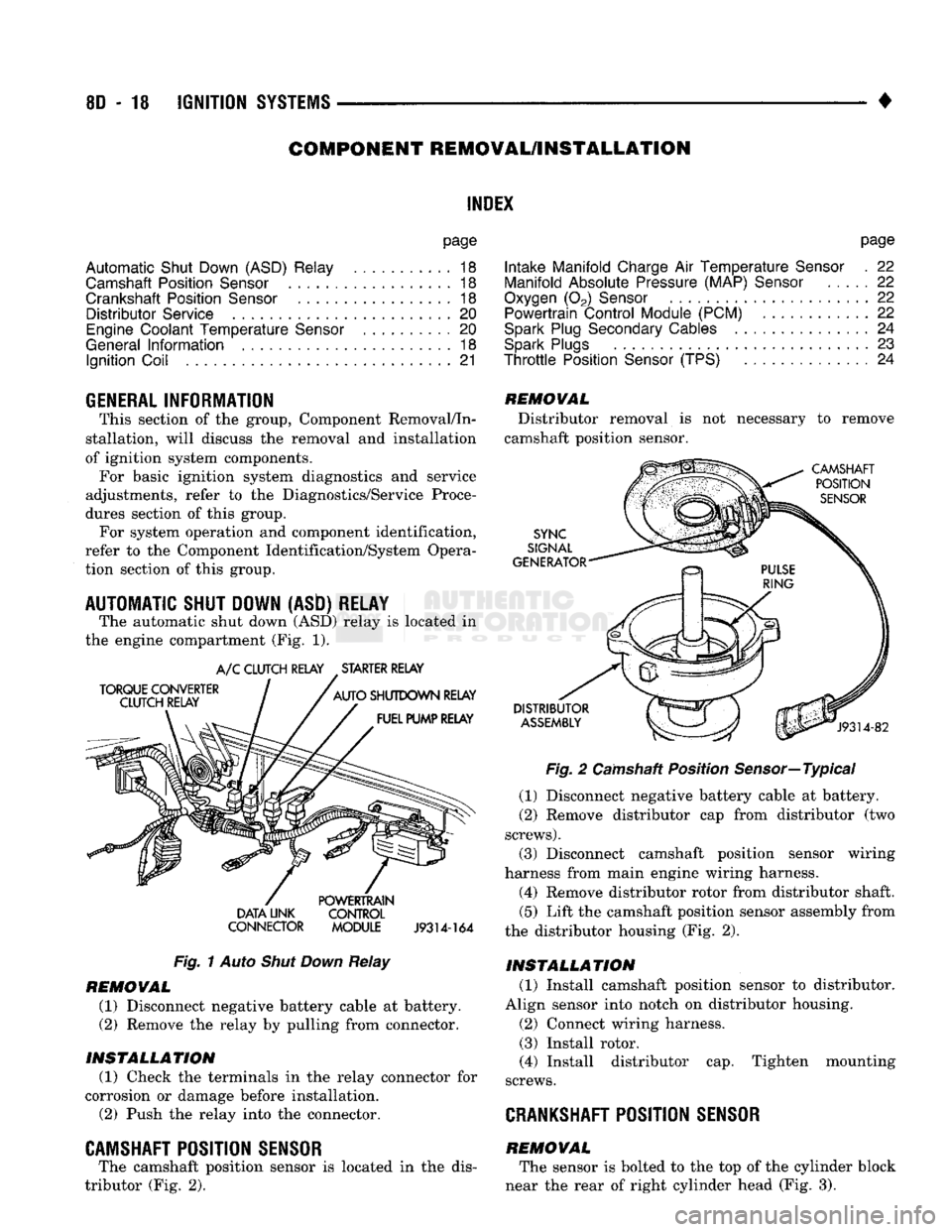
The automatic shut down
(ASD)
relay
is
located
in
the engine compartment
(Fig. 1).
TORQUE CONVERTER
CLUTCH RELAY
A/C
CLUTCH RELAY STARTER RELAY
AUTO
SHUTDOWN RELAY FUEL PUMP RELAY DATA UNK
CONNECTOR POWERTRAIN
CONTROL
MODULE
J9314-164
Fig.
1
Auto
Shut Down
Relay
REMOVAL
(1) Disconnect negative battery cable
at
battery.
(2)
Remove
the
relay
by
pulling from connector.
INSTALLATION
(1) Check
the
terminals
in the
relay connector
for
corrosion
or
damage before installation.
(2)
Push
the
relay into
the
connector.
CAMSHAFT POSITION SENSOR
The camshaft position sensor
is
located
in the
dis
tributor
(Fig. 2).
REMOVAL
Distributor removal
is not
necessary
to
remove
camshaft position sensor.
CAMSHAFT POSITION
SENSOR
SYNC
SIGNAL
GENERATOR
DISTRIBUTOR
ASSEMBLY
J9314-82
Fig.
2
Camshaft Position Sensor—Typical
(1) Disconnect negative battery cable
at
battery.
(2)
Remove distributor
cap
from distributor
(two
screws).
(3) Disconnect camshaft position sensor wiring
harness from main engine wiring harness.
(4) Remove distributor rotor from distributor shaft.
(5)
Lift
the
camshaft position sensor assembly from
the distributor housing
(Fig. 2).
INSTALLATION
(1) Install camshaft position sensor
to
distributor.
Align sensor into notch
on
distributor housing.
(2)
Connect wiring harness.
(3) Install rotor.
(4) Install distributor
cap.
Tighten mounting
screws.
CRANKSHAFT
POSITION SENSOR
REMOVAL The sensor
is
bolted
to the top of the
cylinder block
near
the
rear
of
right cylinder head
(Fig. 3).
Page 375 of 1502
8D
- 24
IGNITION
SYSTEMS
•
.040
GAUGE
SPARK
"PLUG
J908D-10
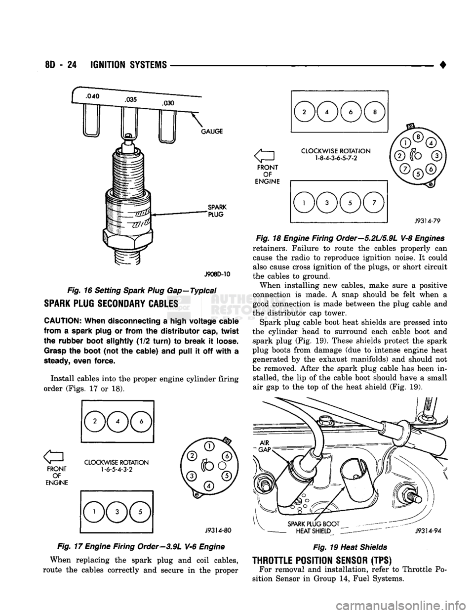
Fig.
16 Setting
Spark Plug
Gap—Typical
SPARK
PLUG
SECONDARY
CABLES
CAUTION:
When disconnecting
a
high voltage cable
from
a
spark plug
or
from
the
distributor cap, twist
the rubber boot slightly
(1/2
turn)
to
break
it
loose.
Grasp
the
boot
(not
the
cable)
and
pull
it off
with
a
steady,
even force.
Install cables into
the
proper engine cylinder firing
order (Figs.
17 or 18).
FRONT OF
ENGINE
CLOCKWISE
ROTATION
1-6-5-4-3-2
J9314-80
Fig.
17
Engine
Firing Order—3.9L V-6
Engine
When replacing
the
spark plug
and
coil cables,
route
the
cables correctly
and
secure
in the
proper a
FRONT OF
ENGINE
CLOCKWISE
ROTATION
1-8-4-3-6-5-7-2
J9314-79
Fig.
18
Engine
Firing Order—5.2U5.9L V-8
Engines
retainers. Failure
to
route
the
cables properly
can
cause
the
radio
to
reproduce ignition noise.
It
could
also cause cross ignition
of the
plugs,
or
short circuit
the cables
to
ground.
When installing
new
cables, make sure
a
positive
connection
is
made.
A
snap should
be
felt when
a
good connection
is
made between
the
plug cable
and
the distributor
cap
tower.
Spark plug cable boot heat shields
are
pressed into
the cylinder head
to
surround each cable boot
and
spark plug
(Fig. 19).
These shields protect
the
spark
plug boots from damage
(due to
intense engine heat generated
by the
exhaust manifolds)
and
should
not
be removed. After
the
spark plug cable
has
been
in
stalled,
the lip of the
cable boot should have
a
small
air
gap to the top of the
heat shield
(Fig. 19).
SPARK
PLUG BOOT
-
HEAT SHIELD
J9314-94
Fig.
19 Heat
Shields
THROTTLE
POSITION
SENSOR
(TPS) For removal
and
installation, refer
to
Throttle
Po
sition Sensor
in
Group
14,
Fuel Systems.
Page 385 of 1502
8E
- 4
INSTRUMENT PANEL
AND
GAUGES
•
MESSAGE CENTER—DIESEL
ENGINE
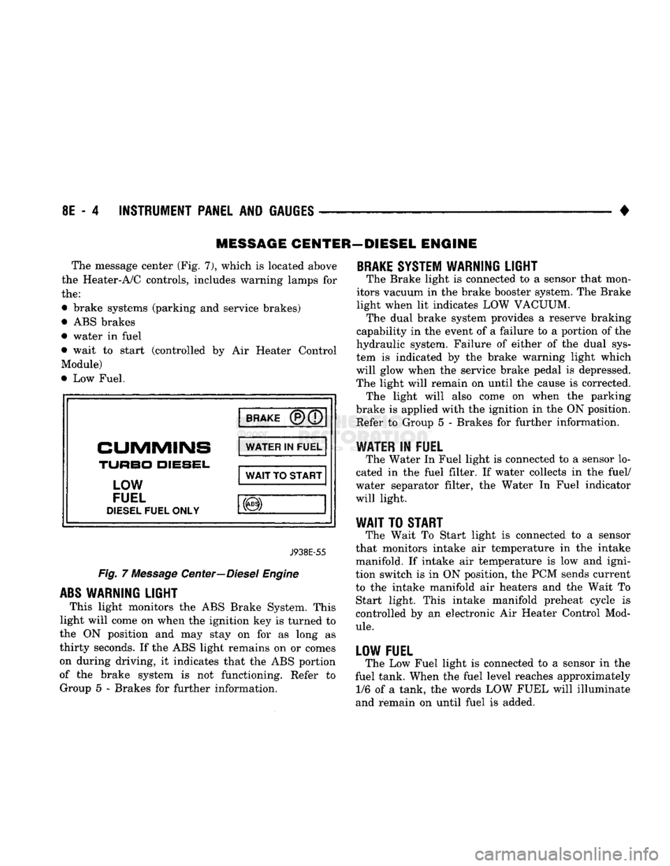
The message center (Fig. 7), which
is
located above
the Heater-A/C controls, includes warning lamps
for
the:
• brake systems (parking
and
service brakes)
• ABS brakes
• water
in
fuel
• wait
to
start (controlled
by Air
Heater Control
Module)
• Low Fuel.
BRAKE
CUMMINS
TURBO
DIESEL,
LOW
FUEL
DIESEL
FUEL ONLY WATER
IN
FUEL
WAIT
TO
START
J938E-55
Fig.
7
Message Center—Diesel Engine
ABS
WARNING LIGHT
This light monitors
the
ABS Brake System. This
light will come
on
when the ignition key
is
turned
to
the
ON
position
and may
stay
on for as
long
as
thirty seconds.
If
the ABS light remains
on or
comes
on during driving,
it
indicates that
the
ABS portion
of
the
brake system
is not
functioning. Refer
to
Group
5 -
Brakes
for
further information.
BRAKE
SYSTEM WARNING LIGHT
The Brake light
is
connected
to a
sensor that mon
itors vacuum
in
the brake booster system. The Brake
light when
lit
indicates LOW VACUUM. The dual brake system provides
a
reserve braking
capability
in
the event
of a
failure
to a
portion
of
the
hydraulic system. Failure
of
either
of the
dual sys
tem
is
indicated
by the
brake warning light which
will glow when
the
service brake pedal
is
depressed.
The light will remain
on
until
the
cause
is
corrected. The light will also come
on
when
the
parking
brake
is
applied with the ignition
in
the ON position. Refer
to
Group
5 -
Brakes
for
further information.
WATER
IN
FUEL
The Water
In
Fuel light
is
connected
to a
sensor lo
cated
in the
fuel filter.
If
water collects
in the
fuel/
water separator filter,
the
Water
In
Fuel indicator
will light.
WAIT
TO
START
The Wait
To
Start light
is
connected
to a
sensor
that monitors intake
air
temperature
in the
intake
manifold.
If
intake
air
temperature
is low and
igni
tion switch
is in
ON position,
the
PCM sends current
to
the
intake manifold
air
heaters
and the
Wait
To
Start light. This intake manifold preheat cycle
is
controlled
by an
electronic
Air
Heater Control Mod
ule.
LOW FUEL
The Low Fuel light
is
connected
to a
sensor
in the
fuel tank. When the fuel level reaches approximately 1/6
of a
tank,
the
words LOW FUEL will illuminate
and remain
on
until fuel
is
added.
Page 404 of 1502
AUDIO SYSTEMS
CONTENTS
SERVICE
PROCEDURES
page
.. 7
TEST PROCEDURES
page
.. 2
GENERAL
INFORMATION
For operation of the factory installed radios, refer
to the Owner Manual supplied with the vehicle. When connecting or disconnecting the Ignition Off
Draw (IOD) connector, it is important that the igni
tion switch be in the OFF position. Failure to place the ignition switch in the OFF po
sition can cause the radio display to become scram
bled when the IOD is disconnected. Connecting the IOD will correct the scrambled display.
INTERFERENCE
ELIMINATION
Many components are used on vehicles equipped
with a radio to suppress radio frequency interference (static). A capacitor is mounted inside the generator and
ground straps are utilized from cab to box and from
the engine to cowl. The previously mentioned Capacitor and Ground
Straps should be securely mounted to a clean ground
surface to work effectively. Radio resistance spark plug wires complete the in
terference suppression system. Faulty or deteriorated spark plug wires should be replaced.
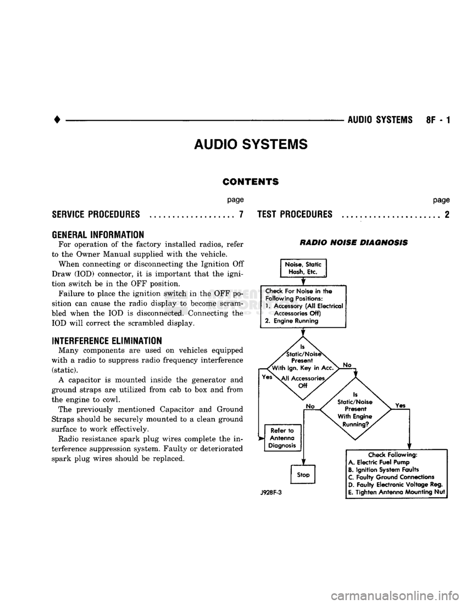
RADIO NOISE DIAGNOSIS
Noise,
Static
Hash,
Etc.
Check
For Noise in
the
Following
Positions:
1.
Accessory (All Electrical
Accessories
Off)
2. Engine Running
Is
'Static/NoiseS
Present
'With
Ign.
Key in Acc.
Yes\^|j
Accessories/
Off
No
Refer
to
Antenna
Diagnosis
f
Stop
No
Is
Static/Noise Present
With Engine
Running?.
Yes
J928F-3
Check
Following:
A.
Electric
Fuel
Pump
B.
Ignition
System
Faults
C.
Faulty Ground Connections
D.
Faulty Electronic Voltage Reg.
E.
Tighten Antenna Mounting Nut
Page 481 of 1502
8W
-6
WIRING DIAGRAMS
•
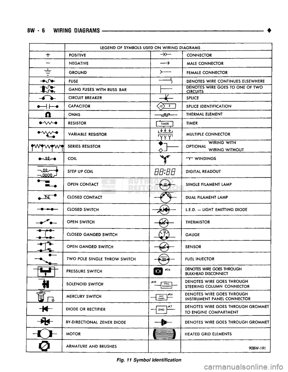
LEGEND
OF SYMBOLS
USED
ON
WIRING DIAGRAMS
+
POSITIVE
CONNECTOR
—
NEGATIVE
—>
MALE
CONNECTOR
_L_
GROUND
>
FEMALE CONNECTOR
FUSE
S DENOTES WIRE CONTINUES ELSEWHERE
GANG
FUSES
WITH
BUSS
BAR
DENOTES WIRE GOES
TO
ONE
OF TWO
CIRCUITS
CIRCUIT
BREAKER
SPLICE
CAPACITOR
<3>2
i
SPLICE
IDENTIFICATION
A
OHMS
cftP—
THERMAL ELEMENT
RESISTOR
| TIMER
|
TIMER
VARIABLE
RESISTOR
1
^ ^ ^ |
'YY Y1
MULTIPLE CONNECTOR
SERIES
RESISTOR
o-l
WIRING
WITH
OPTIONAL WIRING
WITHOUT
COIL Y "Y" WINDINGS
—o
STEP
UP COIL
BB-BB
DIGITAL READOUT
OPEN CONTACT
-0-
SINGLE
FILAMENT LAMP
M
K #
CLOSED
CONTACT
-(5-DUAL FILAMENT LAMP
CLOSED
SWITCH
LE.D.
-
LIGHT
EMITTING
DIODE
OPEN SWITCH —^— THERMISTOR
CLOSED
GANGED SWITCH
GAUGE
mi OPEN GANGED SWITCH
SENSOR
TWO POLE SINGLE THROW SWITCH FUEL INJECTOR
PRESSURE
SWITCH
E
|
#36
DENOTES WIRE
GOES
THROUGH
BULKHEAD DISCONNECT
3i
SOLENOID SWITCH
#" STRG
COLUMN DENOTES WIRE GOES THROUGH
STEERING
COLUMN CONNECTOR
frt
MERCURY
SWITCH
| PANEL
J
DENOTES WIRE GOES THROUGH
INSTRUMENT PANEL CONNECTOR
H«- DIODE
OR
RECTIFIER
j
ENG |
DENOTES WIRE GOES THROUGH GROMMET
TO ENGINE COMPARTMENT
BY-DIRECTIONAL ZENER DIODE DENOTES WIRE GOES THROUGH GROMMET
-o-
MOTOR
HEATED GRID ELEMENTS
0 ARMATURE AND BRUSHES
908W-191
Fig.
11
Symbol
identification
Page 609 of 1502
9
- 4 ENGINES
•
RN861
Fig. 3 Clearance Measurement
CONNECTING ROD BEARING CLEARANCE Engine connecting rod bearing clearances can be
determined by use of Plastigage, or equivalent. The
following is the recommended procedures for the use of Plastigage:
(1) Remove oil film from surface to be checked.
Plastigage is soluble in oil.
(2) Place a piece of Plastigage across the entire
width of the bearing cap shell (Fig. 2). Position the
Plastigage approximately 6.35 mm (1/4 inch) off cen
ter and away from the oil holes. In addition, suspect areas can be checked by placing the Plastigage in the
suspect area. (3) The crankshaft must be turned until the con
necting rod to be checked starts moving toward the
top of the engine. Only then should the rod cap with
Plastigage in place be assembled. Tighten the rod
cap nut to 61 Nnn (45 ft. lbs.) torque. DO NOT ro
tate the crankshaft or the Plastigage may be smeared, giving inaccurate results. (4) Remove the bearing cap and compare the width
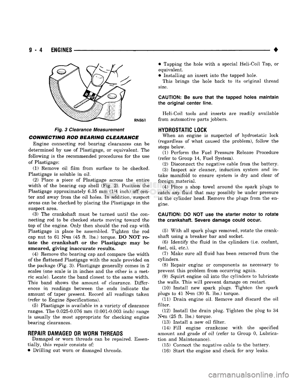
of the flattened Plastigage with the scale provided on
the package (Fig. 3). Plastigage generally comes in 2 scales (one scale is in inches and the other is a met
ric scale). Locate the band closest to the same width.
This band shows the amount of clearance. Differ ences in readings between the ends indicate the
amount of taper present. Record all readings taken (refer to Engine Specifications). (5) Plastigage is available in a variety of clearance
ranges. The 0.025-0.076 mm (0.001-0.003 inch) range
is usually the most appropriate for checking engine
bearing clearances.
REPAIR DAMAGED OR WORN THREADS Damaged or worn threads can be repaired. Essen
tially, this repair consists of:
• Drilling out worn or damaged threads. • Tapping the hole with a special Heli-Coil Tap, or
equivalent.
• Installing an insert into the tapped hole.
This brings the hole back to its original thread
size.
CAUTION:
Be
sure
that
the tapped holes maintain
the original
center
line.
Heli-Coil tools and inserts are readily available
from automotive parts jobbers.
HYDROSTATIC
LOCK
When an engine is suspected of hydrostatic lock
(regardless of what caused the problem), follow the
steps below. (1) Perform the Fuel Pressure Release Procedure
(refer to Group 14, Fuel System). (2) Disconnect the negative cable from the battery.
(3) Inspect air cleaner, induction system and in
take manifold to ensure system is dry and clear of
foreign material. (4) Place a shop towel around the spark plugs to
catch any fluid that may possibly be under pressure
in the cylinder head. Remove the plugs from the en
gine.
CAUTION:
DO NOT use the starter motor to
rotate
the
crankshaft.
Severe
damage
could
occur.
(5) With all spark plugs removed, rotate the crank
shaft using a breaker bar and socket.
(6) Identify the fluid in the cylinders (i.e. coolant,
fuel, oil, etc.).
(7) Make sure all fluid has been removed from the
cylinders. (8) Repair engine or components as necessary to
prevent this problem from occurring again.
(9) Squirt engine oil into the cylinders to lubricate
the walls. This will prevent damage on restart.
(10) Install new spark plugs. Tighten the spark
plugs to 41 N#m (30 ft. lbs.) torque. (11) Drain engine oil. Remove and discard the oil
filter.
(12) Install the drain plug. Tighten the plug to 34
N-m (25 ft. lbs.) torque.
(13) Install a new oil filter.
(14) Fill engine crankcase with the specified
amount and grade of oil (refer to Group 0, Lubrica
tion and Maintenance). (15) Connect the negative cable to the battery.
(16) Start the engine and check for any leaks.