1993 DODGE TRUCK wheel
[x] Cancel search: wheelPage 66 of 1502
•
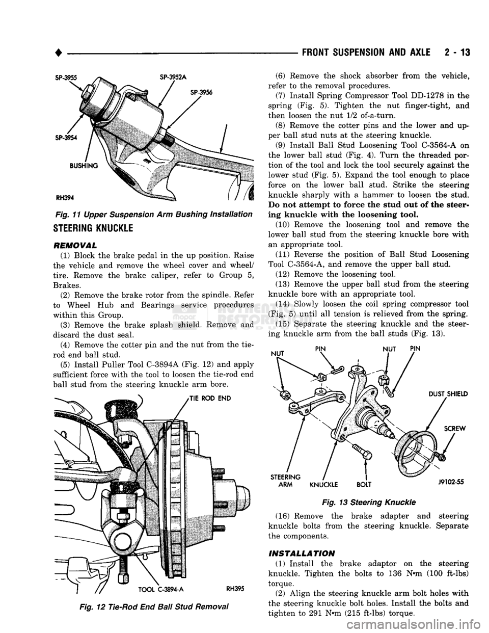
Fig.
11 Upper Suspension Arm Bushing installation
STEERING KNUCKLE
REMOVAL
(1) Block the brake pedal in the up position. Raise
the vehicle and remove the wheel cover and wheel/
tire.
Remove the brake caliper, refer to Group 5,
Brakes. (2) Remove the brake rotor from the spindle. Refer
to Wheel Hub and Bearings service procedures
within this Group.
(3) Remove the brake splash shield. Remove and
discard the dust seal.
(4) Remove the cotter pin and the nut from the tie-
rod end ball stud.
(5)
Install Puller Tool C-3894A (Fig. 12) and apply
sufficient force with the tool to loosen the tie-rod end
ball stud from the steering knuckle arm bore.
Fig.
12 Tie-Rod End
Ball
Stud
Removal
FRONT SUSPENSION
AND
AXLE
2 - 13
Fig.
13 Steering
Knuckle
(16) Remove the brake adapter and steering
knuckle bolts from the steering knuckle. Separate
the components.
INSTALLATION (1) Install the brake adaptor on the steering
knuckle. Tighten the bolts to 136 Nnn (100 ft-lbs)
torque.
(2) Align the steering knuckle arm bolt holes with
the steering knuckle bolt holes. Install the bolts and
tighten to 291 Nnn (215 ft-lbs) torque. (6) Remove the shock absorber from the vehicle,
refer to the removal procedures. (7) Install Spring Compressor Tool DD-1278 in the
spring (Fig. 5). Tighten the nut finger-tight, and
then loosen the nut 1/2 of-a-turn.
(8) Remove the cotter pins and the lower and up
per ball stud nuts at the steering knuckle.
(9) Install Ball Stud Loosening Tool C-3564-A on
the lower ball stud (Fig. 4). Turn the threaded por
tion of the tool and lock the tool securely against the lower stud (Fig. 5). Expand the tool enough to place
force on the lower ball stud. Strike the steering
knuckle sharply with a hammer to loosen the stud.
Do not attempt to force the stud out of the steer
ing knuckle with the loosening tool.
(10) Remove the loosening tool and remove the
lower ball stud from the steering knuckle bore with an appropriate tool.
(11) Reverse the position of Ball Stud Loosening
Tool C-3564-A, and remove the upper ball stud.
(12) Remove the loosening tool.
(13) Remove the upper ball stud from the steering
knuckle bore with an appropriate tool. (14) Slowly loosen the coil spring compressor tool
(Fig. 5) until all tension is relieved from the spring.
(15) Separate the steering knuckle and the steer
ing knuckle arm from the ball studs (Fig. 13).
Page 67 of 1502
2
- 14
FRONT SUSPENSION
AND
AXLE
• (3) Mount the knuckle to the suspension arms and
install the nuts. Tighten the upper nut to 142 Nnn (105 ft-lbs) torque and the lower nut.
• 11/16-16 bolt, to 183 Nnn (135 ft-lbs) torque
• 3/4-16 bolt, to 237 Nnn (175 ft-lbs) torque Install replacement cotter pins. (4) Connect the tie-rod end. Install and tighten the
nut to 61 Nnn (45 ft-lbs) torque. Install a replace
ment cotter pin. (5) Position a replacement dust seal on the steer
ing knuckle. Install the splash shield and tighten the
bolts to 24 Nnn (18 ft. lbs.) torque. (6) Install the shock absorber, refer to the installa
tion procedures.
(7) Install the hub/rotor, refer to the procedures
above.
(8) Install the brake caliper, refer to Group 5,
Brakes for additional installation information.
(9)
Install the wheel and tire, refer to Wheel and
Tire Installation in this section. Lower the vehicle.
(10) Test the vehicle brakes and the front suspen
sion for proper operation.
FRONT
SUSPENSION—4WD VEHICLES
STABILIZER
BAR REMOVAL
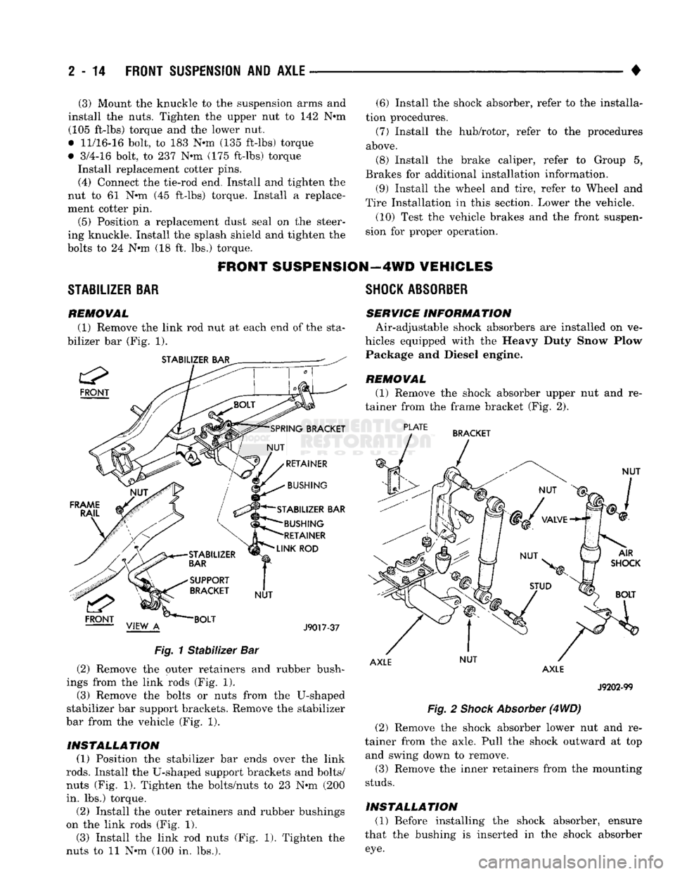
(1) Remove the link rod nut at each end of the sta
bilizer bar (Fig. 1).
STABILIZER BAR
FRONT
STABILIZER BAR BUSHING
RETAINER
LINK
ROD
J9017-37
Fig.
1
Stabilizer
Bar (2) Remove the outer retainers and rubber bush
ings from the link rods (Fig. 1). (3) Remove the bolts or nuts from the U-shaped
stabilizer bar support brackets. Remove the stabilizer
bar from the vehicle (Fig. 1).
INSTALLATION (1) Position the stabilizer bar ends over the link
rods.
Install the U-shaped support brackets and bolts/
nuts (Fig. 1). Tighten the bolts/nuts to 23 Nnn (200
in. lbs.) torque.
(2) Install the outer retainers and rubber bushings
on the link rods (Fig. 1). (3) Install the link rod nuts (Fig. 1). Tighten the
nuts to 11 Nnn (100 in. lbs.).
SHOCK
ABSORBER
SERVICE INFORM
A TION Air-adjustable shock absorbers are installed on ve
hicles equipped with the Heavy Duty Snow Plow Package and Diesel engine.
REMOVAL
(1) Remove the shock absorber upper nut and re
tainer from the frame bracket (Fig. 2).
PLATE
BRACKET
NUT
AXLE NUT
AXLE
J9202-99
Fig.
2
Shock
Absorber
(4
WD)
(2) Remove the shock absorber lower nut and re
tainer from the axle. Pull the shock outward at top and swing down to remove.
(3) Remove the inner retainers from the mounting
studs.
INSTALLATION (1) Before installing the shock absorber, ensure
that the bushing is inserted in the shock absorber
eye.
Page 73 of 1502
2
- 20
FRONT SUSPENSION
AND
AXLE
•
INSTALLATION
(1) Apply a light coating of gear lubricant on the
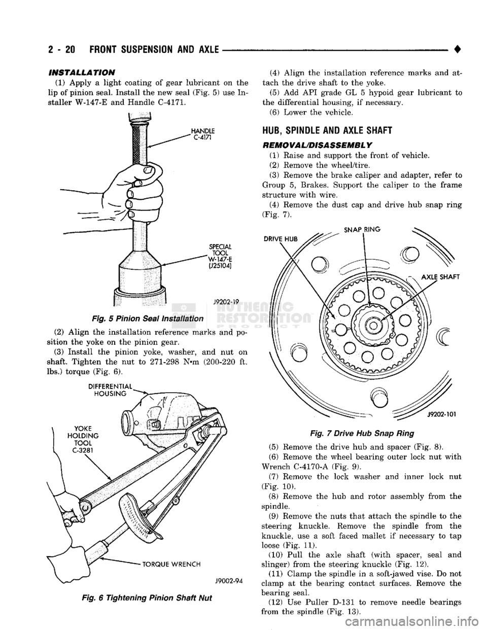
lip of pinion seal. Install the new seal (Fig. 5) use In
staller W-147-E and Handle C-4171.
Fig.
5
Pinion
Seal
Installation
(2) Align the installation reference marks and po
sition the yoke on the pinion gear.
(3) Install the pinion yoke, washer, and nut on
shaft. Tighten the nut to 271-298 N»m (200-220 ft.
lbs.) torque (Fig. 6).
DIFFERENTIAL
Fig.
6 Tightening
Pinion
Shaft Nut (4) Align the installation reference marks and at
tach the drive shaft to the yoke.
(5) Add API grade GL 5 hypoid gear lubricant to
the differential housing, if necessary.
(6) Lower the vehicle.
HUB, SPINDLE
AND
AXLE SHAFT
REMOVAL/DISASSEMBLY
(1) Raise and support the front of vehicle.
(2) Remove the wheel/tire.
(3) Remove the brake caliper and adapter, refer to
Group 5, Brakes. Support the caliper to the frame
structure with wire.
(4) Remove the dust cap and drive hub snap ring
(Fig. 7).
Fig.
7 Drive Hub
Snap Ring
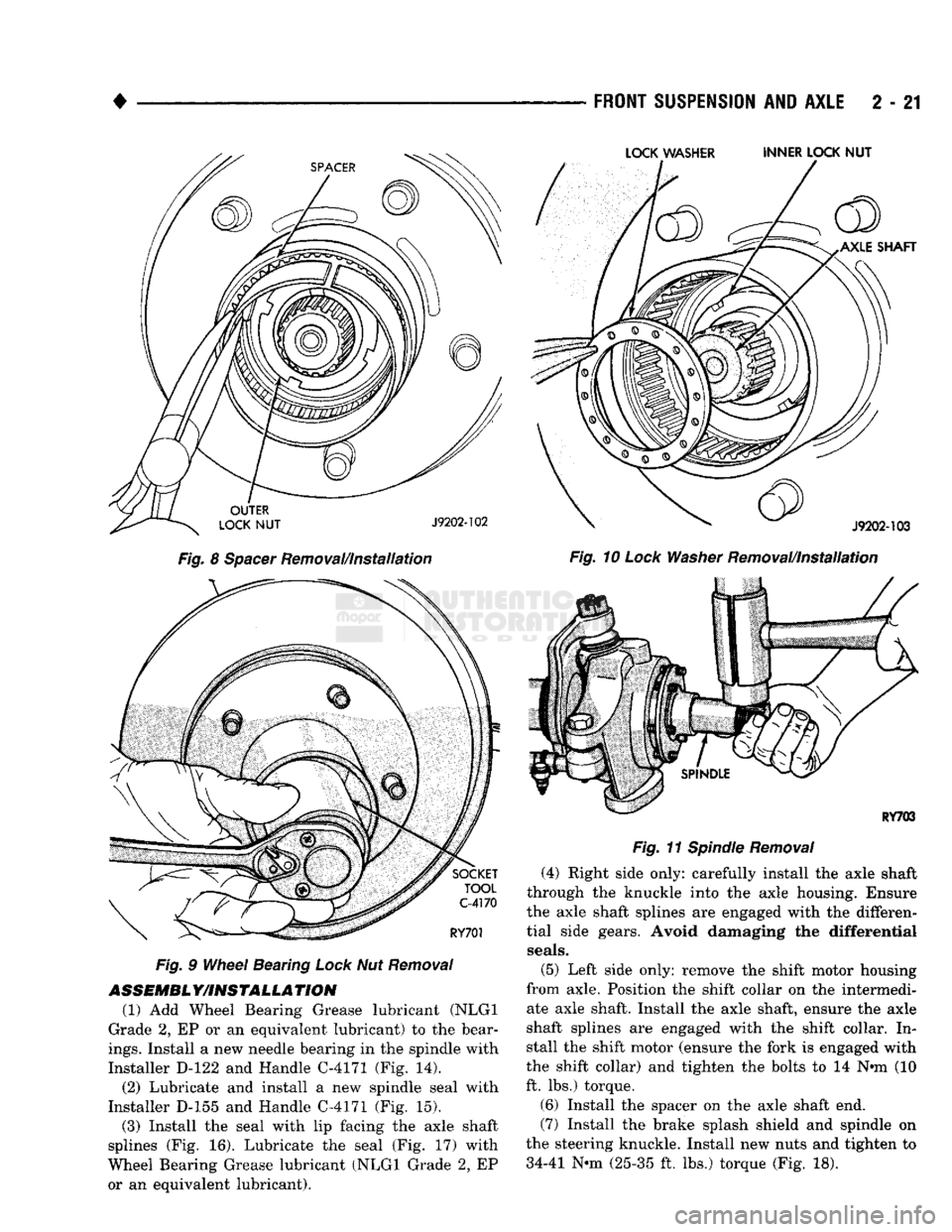
(5) Remove the drive hub and spacer (Fig. 8).
(6) Remove the wheel bearing outer lock nut with
Wrench C-4170-A (Fig. 9). (7) Remove the lock washer and inner lock nut
(Fig. 10).
(8) Remove the hub and rotor assembly from the
spindle.
(9) Remove the nuts that attach the spindle to the
steering knuckle. Remove the spindle from the
knuckle, use a soft faced mallet if necessary to tap
loose (Fig. 11).
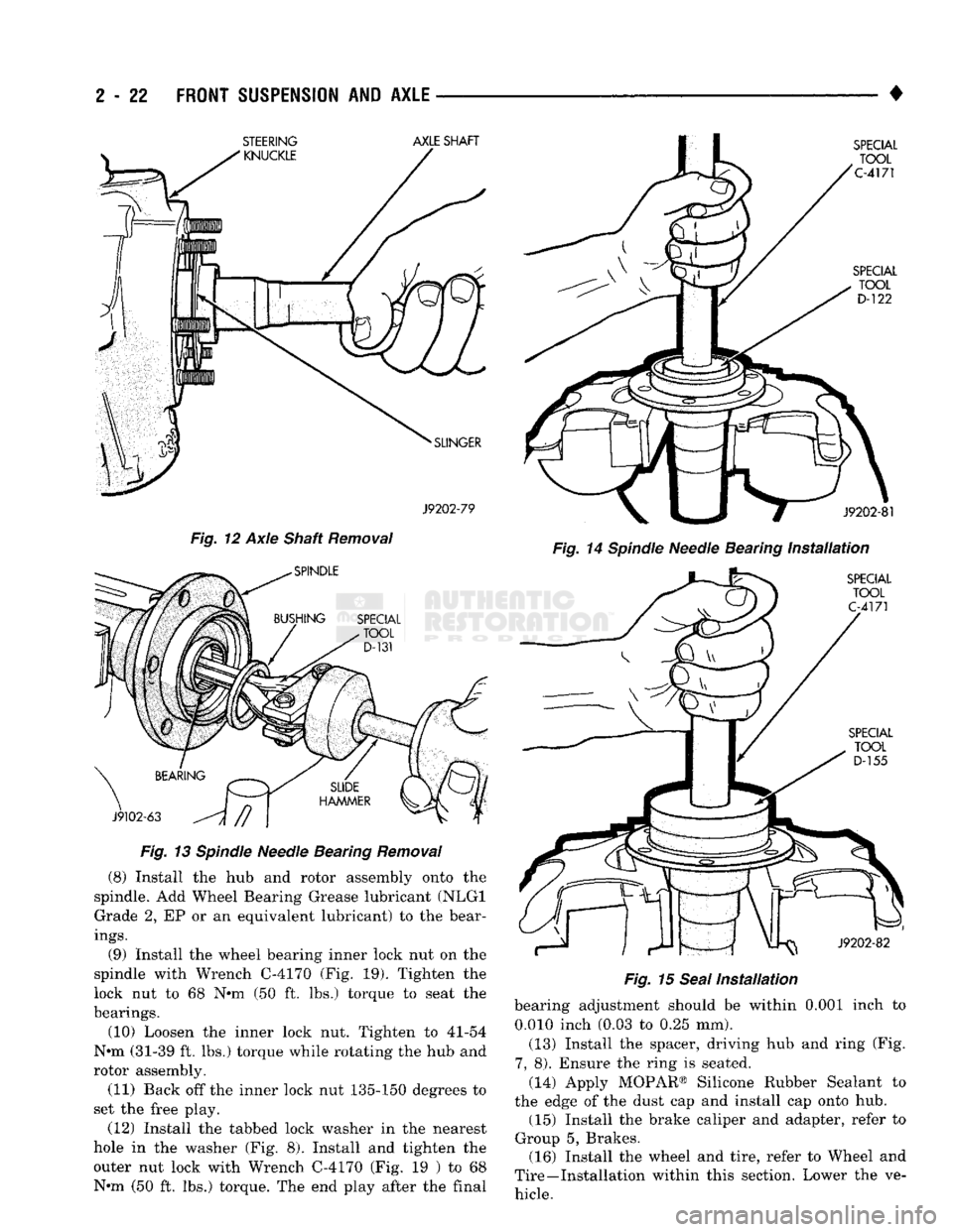
(10) Pull the axle shaft (with spacer, seal and
slinger) from the steering knuckle (Fig. 12). (11) Clamp the spindle in a soft-jawed vise. Do not
clamp at the bearing contact surfaces. Remove the
bearing seal. (12) Use Puller D-131 to remove needle bearings
from the spindle (Fig. 13).
Page 74 of 1502
•
Fig.
8
Spacer
Removal/Installation
Fig.
9
Wheel
Bearing
Lock
Nut
Removal
ASSEMBL
Y/INSTALLA
TION
(1) Add Wheel Bearing Grease lubricant (NLGI
Grade 2, EP or an equivalent lubricant) to the bear
ings.
Install a new needle bearing in the spindle with
Installer D-122 and Handle C-4171 (Fig. 14).
(2) Lubricate and install a new spindle seal with
Installer D-155 and Handle C-4171 (Fig. 15).
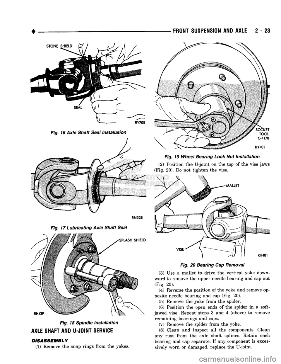
(3) Install the seal with lip facing the axle shaft
splines (Fig. 16). Lubricate the seal (Fig. 17) with
Wheel Bearing Grease lubricant (NLGI Grade 2, EP or an equivalent lubricant).
FRONT
SUSPENSION
AND
AXLE
2 - 21
LOCK
WASHER INNER LOCK
NUT
Fig.
10
Lock
Washer
Removal/Installation
Fig.
11
Spindle
Removal
(4) Right side only: carefully install the axle shaft
through the knuckle into the axle housing. Ensure
the axle shaft splines are engaged with the differen
tial side gears. Avoid damaging the differential
seals.
(5) Left side only: remove the shift motor housing
from axle. Position the shift collar on the intermedi ate axle shaft. Install the axle shaft, ensure the axle
shaft splines are engaged with the shift collar. In stall the shift motor (ensure the fork is engaged with
the shift collar) and tighten the bolts to 14 Nnn (10
ft. lbs.) torque.
(6) Install the spacer on the axle shaft end.
(7) Install the brake splash shield and spindle on
the steering knuckle. Install new nuts and tighten to 34-41 Nnn (25-35 ft. lbs.) torque (Fig. 18).
Page 75 of 1502
2
- 22
FRONT SUSPENSION
AND
AXLE
——
J9202-79
Fig. 12 Axle Shaft Removal
Fig. 13 Spindle Needle Bearing Removal (8) Install the hub and rotor assembly onto the
spindle. Add Wheel Bearing Grease lubricant (NLGI Grade 2, EP or an equivalent lubricant) to the bear
ings.
(9) Install the wheel bearing inner lock nut on the
spindle with Wrench C-4170 (Fig. 19). Tighten the
lock nut to 68 N*m (50 ft. lbs.) torque to seat the
bearings.
(10) Loosen the inner lock nut. Tighten to 41-54
N*m (31-39 ft. lbs.) torque while rotating the hub and
rotor assembly.
(11) Back off the inner lock nut 135-150 degrees to
set the free play.
(12) Install the tabbed lock washer in the nearest
hole in the washer (Fig. 8). Install and tighten the outer nut lock with Wrench C-4170 (Fig. 19 ) to 68
N«m (50 ft. lbs.) torque. The end play after the final •
Fig. 14 Spindle Needle Bearing Installation Fig. 15 Seal Installation bearing adjustment should be within 0.001 inch to
0.010 inch (0.03 to 0.25 mm).
(13) Install the spacer, driving hub and ring (Fig.
7,
8). Ensure the ring is seated.
(14) Apply MOPAR® Silicone Rubber Sealant to
the edge of the dust cap and install cap onto hub. (15) Install the brake caliper and adapter, refer to
Group 5, Brakes. (16) Install the wheel and tire, refer to Wheel and
Tire—Installation within this section. Lower the ve hicle. STEERING
AXLE
SHAFT
Page 76 of 1502
•
FRONT
SUSPENSION
AND
AXLE
2 - 23
RN328
Fig.
17 Lubricating Axle Shaft
Seal
Fig.
18
Spindle
Installation
AXLE SHAFT AND
U-JOINT
SERVICE DISASSEMBLY
(1) Remove the snap rings from the yokes.
Fig.
19
Wheel
Bearing Lock Nut
Installation
(2)
Position the U-joint on the top of the vise jaws
(Fig. 20). Do not tighten the vise.
Fig.
20 Bearing Cap
Removal
(3)
Use a mallet to drive the vertical yoke down
ward to remove the upper needle bearing and cap out (Fig. 20).
(4)
Reverse the position of the yoke and remove op
posite needle bearing and cap (Fig. 20).
(5)
Remove the yoke from the spider.
(6)
Position the open ends of the spider in a soft-
jawed vise. Repeat steps 3 and 4 (above) to remove remaining bearings and caps.
(7) Remove the spider from the yoke.
(8) Clean and inspect all the components. Clean
any rust from the axle shaft splines. Retain each
bearing and cap separate. If any component is exces sively worn or damaged, replace the U-joint.
Page 81 of 1502
2 - 28
FRONT
SUSPENSION
AND
AXLE
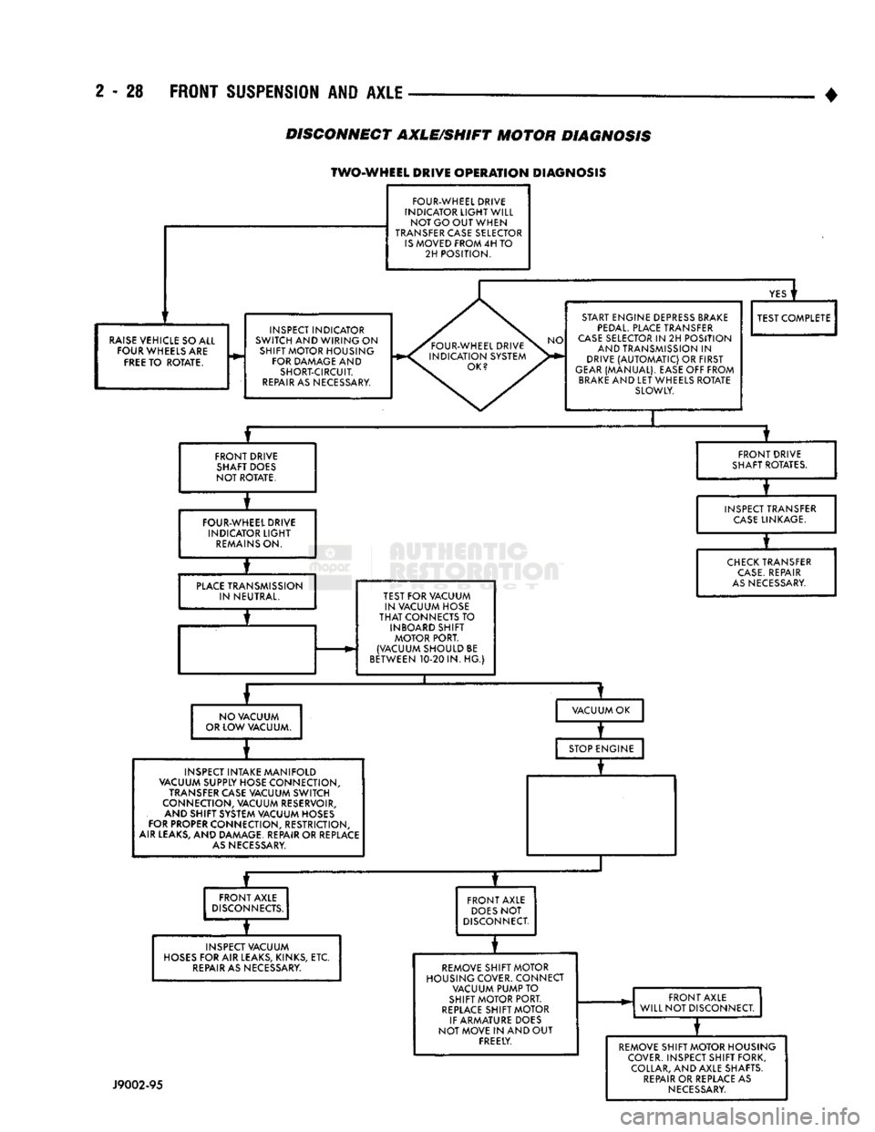
DISCONNECT
AXLE/SHIFT
MOTOR
DIAGNOSIS
TWO-WHEEL DRIVE
OPERATION
DIAGNOSIS
FOUR-WHEEL DRIVE
INDICATOR
LIGHT
WILL NOT GO OUT WHEN
TRANSFER CASE SELECTOR
IS
MOVED FROM 4H TO 2H POSITION.
RAISE
VEHICLE SO ALL FOUR WHEELS ARE
FREE
TO ROTATE. INSPECT INDICATOR
SWITCH AND WIRING ON SHIFT MOTOR HOUSING FOR DAMAGE AND SHORT-CIRCUIT.
REPAIR
AS NECESSARY.
YES
i
START ENGINE DEPRESS BRAKE
PEDAL.
PLACE TRANSFER
CASE
SELECTOR IN 2H POSITION AND TRANSMISSION IN
DRIVE
(AUTOMATIC)
OR FIRST
GEAR
(MANUAL). EASE OFF FROM
BRAKE
AND LET WHEELS ROTATE SLOWLY. TEST COMPLETE
FRONT DRIVE SHAFT DOES
NOT ROTATE. FRONT DRIVE
SHAFT ROTATES.
FOUR-WHEEL DRIVE INDICATOR
LIGHT
REMAINS
ON. INSPECT TRANSFER
CASE
LINKAGE.
PLACE
TRANSMISSION IN NEUTRAL. TEST FOR VACUUM
IN VACUUM HOSE
THAT
CONNECTS TO INBOARD SHIFT MOTOR PORT.
(VACUUM SHOULD BE
BETWEEN 10-20 IN. HG.)
CHECK
TRANSFER
CASE.
REPAIR
AS
NECESSARY.
NO VACUUM
OR LOW VACUUM. VACUUM OK
INSPECT INTAKE MANIFOLD
VACUUM SUPPLY HOSE CONNECTION,
TRANSFER CASE VACUUM SWITCH
CONNECTION, VACUUM RESERVOIR, AND SHIFT SYSTEM VACUUM HOSES
FOR PROPER CONNECTION, RESTRICTION,
AIR LEAKS, AND DAMAGE. REPAIR OR REPLACE
AS
NECESSARY. STOP ENGINE
—r~
FRONT AXLE
DISCONNECTS.
INSPECT VACUUM
HOSES
FOR AIR LEAKS, KINKS, ETC.
REPAIR
AS NECESSARY. FRONT AXLE
DOES
NOT
DISCONNECT.
REMOVE SHIFT MOTOR
HOUSING COVER. CONNECT VACUUM PUMP TO
SHIFT MOTOR PORT.
REPLACE
SHIFT MOTOR
IF ARMATURE DOES
NOT MOVE IN AND OUT FREELY. FRONT AXLE
WILL NOT DISCONNECT.
J9002-95
REMOVE SHIFT MOTOR HOUSING
COVER. INSPECT SHIFT FORK, COLLAR, AND AXLE SHAFTS.
REPAIR
OR REPLACE AS
NECESSARY
Page 82 of 1502
FRONT
SUSPENSION AND
AXLE
2 - 29
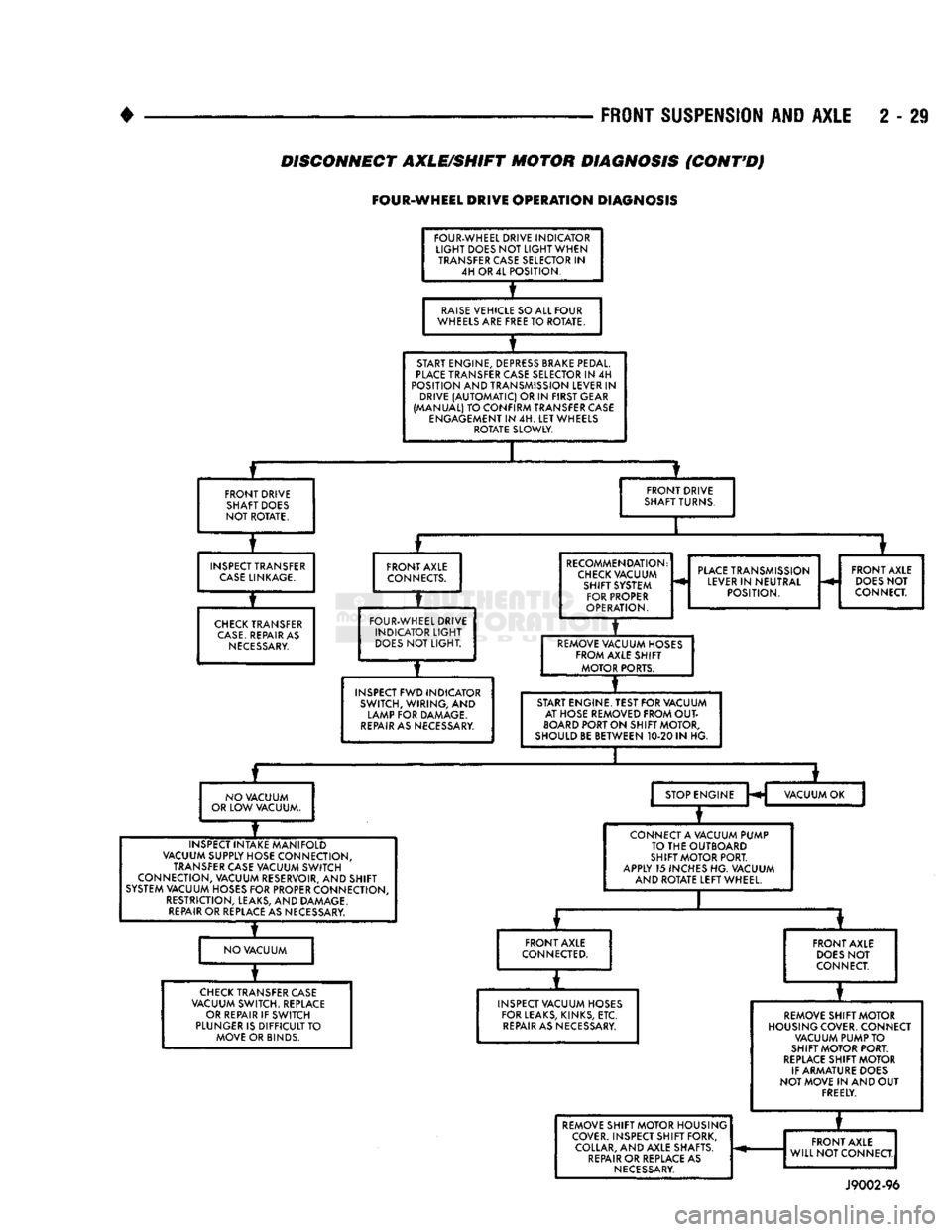
DISCONNECT AXLE/SHIFT MOTOR DIAGNOSIS
(CONT'D)
FOUR-WHEEL
DRIVE
OPERATION
DIAGNOSIS
FOUR-WHEEL DRIVE INDICATOR
LIGHT
DOES NOT
LIGHT
WHEN TRANSFER CASE SELECTOR IN 4H OR 4L POSITION.
RAISE
VEHICLE SO ALL FOUR
WHEELS ARE FREE TO ROTATE.
START ENGINE, DEPRESS BRAKE PEDAL.
PLACE
TRANSFER CASE SELECTOR IN 4H
POSITION AND TRANSMISSION LEVER IN DRIVE
(AUTOMATIC)
OR IN FIRST GEAR
(MANUAL) TO CONFIRM TRANSFER CASE ENGAGEMENT IN 4H. LET WHEELS ROTATE SLOWLY.
FRONT DRIVE SHAFT DOES
NOT ROTATE. FRONT DRIVE
SHAFT TURNS.
INSPECT TRANSFER
CASE
LINKAGE.
CHECK
TRANSFER
CASE.
REPAIR AS
NECESSARY.
FRONT AXLE
CONNECTS.
FOUR-WHEEL DRIVE INDICATOR
LIGHT
DOES
NOT LIGHT.
INSPECT FWD INDICATOR SWITCH, WIRING, AND
LAMP FOR DAMAGE.
REPAIR
AS NECESSARY. RECOMMENDATION:
CHECK
VACUUM SHIFT SYSTEM FOR PROPER
OPERATION.
PLACE
TRANSMISSION
LEVER IN NEUTRAL POSITION. FRONT AXLE
DOES
NOT
CONNECT.
REMOVE VACUUM HOSES FROM AXLE SHIFT MOTOR PORTS.
START ENGINE. TEST FOR VACUUM AT HOSE REMOVED FROM
OUT
BOARD
PORT ON SHIFT MOTOR,
SHOULD BE BETWEEN 10-20 IN HG.
NO VACUUM
OR LOW VACUUM. STOP ENGINE
H VACUUM OK
INSPECT INTAKE MANIFOLD
VACUUM SUPPLY HOSE CONNECTION, TRANSFER CASE VACUUM SWITCH
CONNECTION, VACUUM RESERVOIR, AND SHIFT
SYSTEM VACUUM HOSES FOR PROPER CONNECTION, RESTRICTION, LEAKS, AND DAMAGE.
REPAIR
OR REPLACE AS NECESSARY. CONNECT A VACUUM PUMP
TO THE OUTBOARD
SHIFT MOTOR PORT.
APPLY 15 INCHES HG. VACUUM AND ROTATE LEFT WHEEL.
NO VACUUM FRONT AXLE
CONNECTED.
CHECK
TRANSFER CASE
VACUUM SWITCH. REPLACE OR REPAIR IF SWITCH
PLUNGER IS DIFFICULT TO MOVE OR BINDS. FRONT AXLE
DOES
NOT
CONNECT.
INSPECT VACUUM HOSES FOR LEAKS, KINKS, ETC.
REPAIR
AS NECESSARY. REMOVE SHIFT MOTOR
HOUSING COVER. CONNECT VACUUM PUMP TO
SHIFT MOTOR PORT.
REPLACE
SHIFT MOTOR
IF ARMATURE DOES
NOT MOVE IN AND OUT FREELY. REMOVE SHIFT MOTOR HOUSING
COVER. INSPECT SHIFT FORK, COLLAR, AND AXLE SHAFTS.
REPAIR
OR REPLACE AS
NECESSARY.
*
REMOVE SHIFT MOTOR HOUSING
COVER. INSPECT SHIFT FORK, COLLAR, AND AXLE SHAFTS.
REPAIR
OR REPLACE AS
NECESSARY.
FRONT AXLE
WILL NOT CONNECT.
REMOVE SHIFT MOTOR HOUSING
COVER. INSPECT SHIFT FORK, COLLAR, AND AXLE SHAFTS.
REPAIR
OR REPLACE AS
NECESSARY.
FRONT AXLE
WILL NOT CONNECT.
REMOVE SHIFT MOTOR HOUSING
COVER. INSPECT SHIFT FORK, COLLAR, AND AXLE SHAFTS.
REPAIR
OR REPLACE AS
NECESSARY.
J9002-96