1993 DODGE TRUCK wheel
[x] Cancel search: wheelPage 13 of 1502
8 INTRODUCTION
•
VEHICLE
WEIGHTS
(CONT'D)
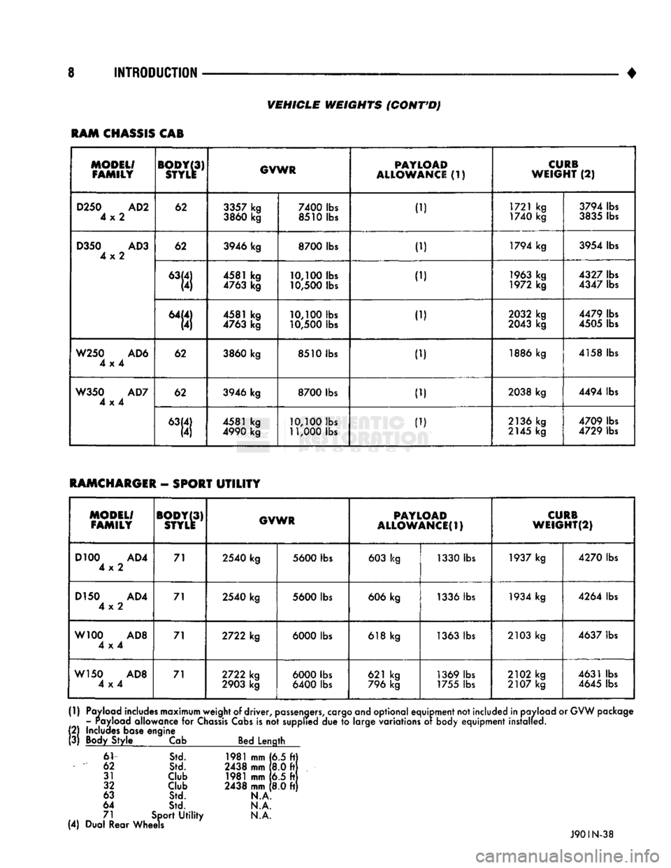
RAM
CHASSIS
CAB
MODEL/
FAMILY
BODY(3)
STYLE
GVWR
PAYLOAD
ALLOWANCE
(1)
CURB
WEIGHT
(2)
D250
AD2
4x2
62
3357
kg
3860
kg
7400
lbs
8510 lbs 1721 kg
1740 kg
3794 lbs
3835
lbs
D350
AD3
4x2
62
3946 kg
8700
lbs
ID
1794 kg
3954 lbs
D350
AD3
4x2
4581 kg
4763
kg
10,100
lbs
10,500
lbs
..,
1963
kg
1972 kg
4327
lbs
4347
lbs
D350
AD3
4x2
"111 4581 kg
4763
kg
10,100
lbs
10,500
lbs
1.1
2032
kg
2043
kg 4479 lbs
4505
lbs
W250
AD6
4x4
62
3860
kg
8510 lbs
1.) 1886 kg
4158 lbs
W350
AD7
4x4
62
3946 kg
8700
lbs
ID
2038 kg
4494 lbs
W350
AD7
4x4
4581 kg
4990
kg
10,100
lbs
11,000
lbs
ID
2136 kg
2145
kg 4709 lbs
4729 lbs
RAMCHARGER
-
SPORT
UTILITY
MODEL/
FAMILY
BODY(3)
STYLE
GVWR
PAYLOAD
ALLOWANCES)
CURB
WEIGHT(2)
D100
AD4
4x2 71
2540
kg
5600
lbs
603
kg 1330 lbs
1937
kg
4270
lbs
D150
AD4
4x2 71
2540
kg
5600
lbs
606
kg
1336
lbs
1934
kg
4264
lbs
W100
AD8
4x4 71
2722
kg
6000
lbs
618
kg
1363
lbs
2103
kg
4637
lbs
W150
AD8
4x4 71
2722
kg
2903
kg
6000
lbs
6400
lbs 621 kg
796
kg
1369
lbs
1755
lbs
2102
kg
2107
kg
4631
lbs
4645
lbs
(1)
Payload includes maximum weight
of
driver,
passengers,
cargo and optional equipment not included in payload
or
GVW package - Payload allowance
for
Chassis
Cabs
is
not
supplied
due to
large variations
of
body equipment installed.
!
2)
Includes base engine
3)
Body Style
Cab
Bed Length
6V
Std.
1981
mm
[6.5 ft)
62
Std.
2438
mm
8.0 ft
31
Club
1981
mm
6.5 ft
32
Club
2438
mm
8.0 ft
63
Std.
N.A
64
Std.
N.A.
71 Sport
Utility N.A.
(4) Dual Rear Wheels
J90IN-38
Page 14 of 1502
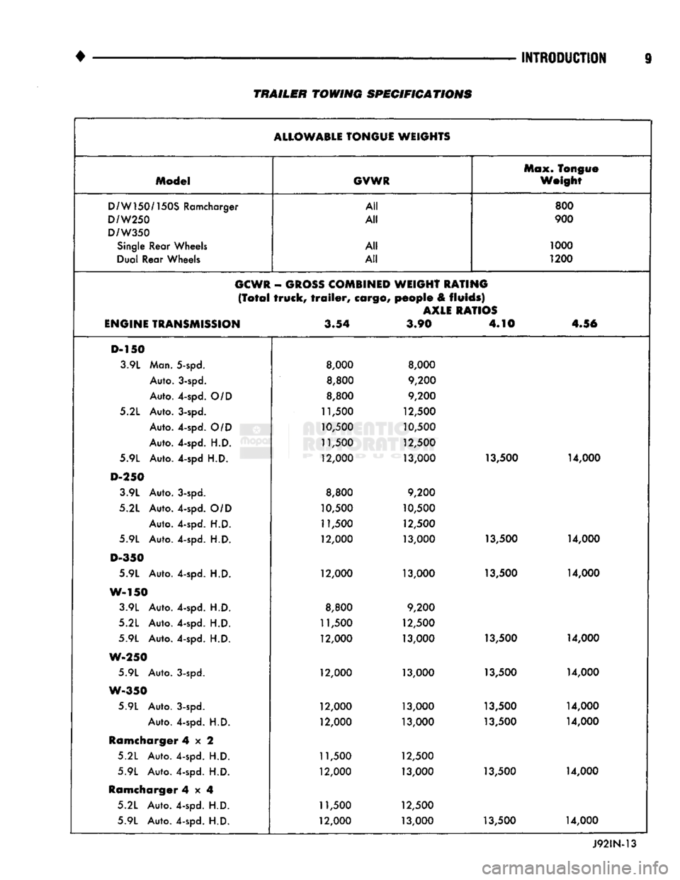
TRAILER TOWING
SPECIFICATIONS
ALLOWABLE
TONGUE WEIGHTS Max. Tongue
Model
GVWR
Weight
D/W150/150S
Ramcharger All
800
D/W250
All
900
D/W350
Single
Rear Wheels All
1000
Dual Rear Wheels All
1200
GCWR
-
GROSS
COMBINED
WEIGHT RATING
(Total
truck,
trailer,
cargo,
people
&
fluids)
AXLE
RATIOS
ENGINE
TRANSMISSION
3.54
3.90 4.10
4.56
D-150 3.9L Man. 5-spd.
8,000 8,000
Auto. 3-spd.
8,800
9,200
Auto. 4-spd.
O/D
8,800
9,200
5.2L Auto. 3-spd.
11,500
12,500
Auto. 4-spd.
O/D
10,500
10,500
Auto. 4-spd.
H.D.
11,500
12,500
5.9L Auto. 4-spd
H.D.
12,000
13,000 13,500
14,000
D-250
3.9L Auto. 3-spd.
8,800
9,200
5.2L Auto. 4-spd.
O/D
10,500 10,500
Auto. 4-spd.
H.D.
11,500
12,500
5.9L Auto. 4-spd.
H.D.
12,000
13,000 13,500
14,000
D-350
5.9L Auto. 4-spd.
H.D.
12,000
13,000 13,500 14,000
W-150 3.9L Auto. 4-spd.
H.D.
8,800
9,200
5.2L Auto. 4-spd.
H.D.
11,500
12,500
5.9L Auto. 4-spd.
H.D.
12,000
13,000 13,500
14,000
W-250
5.9L Auto. 3-spd.
12,000
13,000 13,500 14,000
W-350
5.9L Auto. 3-spd.
12,000 13,000 13,500 14,000
Auto. 4-spd.
H.D.
12,000
13,000 13,500 14,000
Ramcharger
4x2
5.2L Auto. 4-spd.
H.D.
11,500 12,500
5.9L Auto. 4-spd.
H.D.
12,000 13,000 13,500 14,000
Ramcharger
4x4
5.2L Auto. 4-spd.
H.D.
11,500 12,500
5.9L Auto. 4-spd.
H.D.
12,000
13,000 13,500 14,000
Page 21 of 1502
0 - 2
LUBRICATION
AND
MAINTENANCE
• Commercial service
When a vehicle is continuously subjected to severe
driving conditions, lubricate:
• Body components
• All the driveline coupling joints
• Steering linkage More often than normal driving conditions
DUSTY
AREAS
With this type of severe driving condition, special
care should be given to the:
• Engine air cleaner filter
• PCV filter
• Crankcase ventilation system
• Brake booster control valve air filter. Verify that the filters and the associated compo
nents are clean. Also verify that they are functioning
effectively. This will minimize the amount of abra sive particles that enter the engine.
OFF-ROAD
(4WD)
OPERATION
After off-road (4WD) operation, inspect the under
side of the vehicle. Inspect the:
• Tires
• Body structure
• Steering components
• Suspension components • Exhaust system
• Threaded fasteners
HARSH
SURFACE ENVIRONMENTS
After extended operation in harsh environments,
the brake drums, brake linings, and rear wheel bear ings should be inspected and cleaned. This will pre
vent wear and erratic brake action.
ROUTINE MAINTENANCE
The following routine maintenance is recommended
on a monthly basis: TIRES—Inspect the tires for unusual wear/damage.
Determine if the inflation pressure is adequate for
the vehicle load. BATTERY—Inspect and clean the terminals.
Tighten the terminals if necessary. FLUIDS—Determine if the component fluid levels
are acceptable. Add fluid, if necessary. LIGHTS/ELECTRICAL—Test all the electrical sys
tems in the vehicle for proper operation. It is also recommended that the engine oil and the
washer fluid level be determined at each fuel fill-up.
VEHICLE
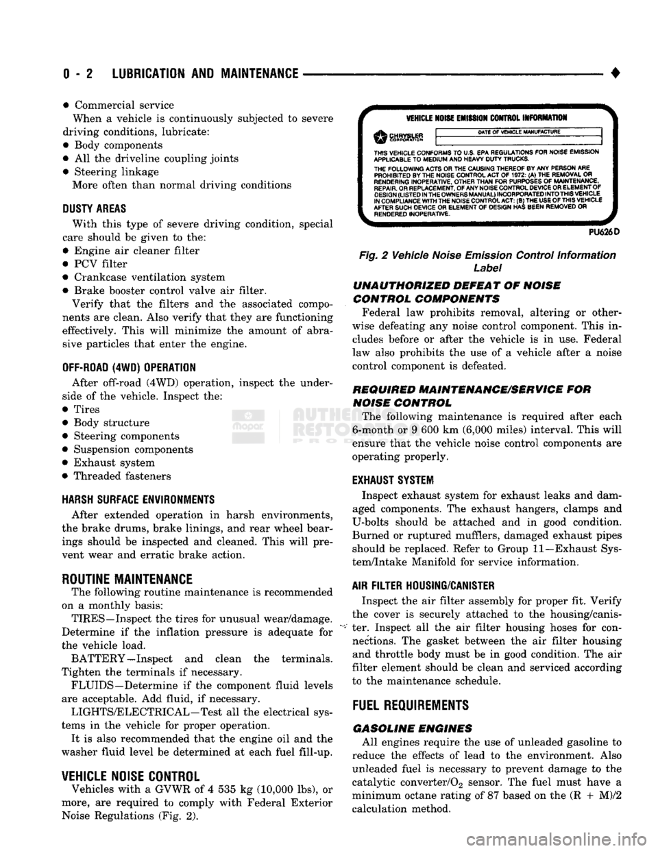
NOISE CONTROL
Vehicles with a GVWR of 4 535 kg (10,000 lbs), or
more, are required to comply with Federal Exterior Noise Regulations (Fig. 2).
VEHICLE
NOISE
EMISSION
CONTROL INFORMATION
DATE
OF
VEHICLE
MANUFACTURE
THIS
VEHICLE CONFORMS
TO
U.S. EPA REGULATIONS FOR NOISE EMISSION
APPLICABLE
TO
MEDIUM
AND HEAVY
DUTY
TRUCKS. THE
FOLLOWING
ACTS OR THE CAUSING THEREOF BY ANY PERSON ARE PROHIBITED BY THE NOISE CONTROL ACT
OF 1972. (A) THE
REMOVAL
OR
RENDERING
INOPERATIVE, OTHER
THAN
FOR
PURPOSES
OF
MAINTENANCE,
REPAIR.
OR REPLACEMENT, OF ANY NOISE CONTROL DEVICE OR ELEMENT OF
DESIGN
(LISTED
IN
THE
OWNERS
MANUAL)
INCORPORATED
INTO
THIS
VEHICLE
IN COMPLIANCE
WITH
THE NOISE CONTROL
ACT:
(B) THE
USE
OF
THIS
VEHICLE
AFTER SUCH DEVICE
OR
ELEMENT
OF
DESIGN HAS BEEN REMOVED
OR
RENDERED
INOPERATIVE.
PU626D
Fig.
2 Vehicle
Noise
Emission
Control Information
Label
UNAUTHORIZED
DEFEAT
OF
NOISE
CONTROL COMPONENTS
Federal law prohibits removal, altering or other
wise defeating any noise control component. This in
cludes before or after the vehicle is in use. Federal
law also prohibits the use of a vehicle after a noise
control component is defeated.
REQUIRED MAINTENANCE/SERVICE
FOR
NOISE
CONTROL
The following maintenance is required after each
6-month or 9 600 km (6,000 miles) interval. This will
ensure that the vehicle noise control components are
operating properly.
EXHAUST SYSTEM
Inspect exhaust system for exhaust leaks and dam
aged components. The exhaust hangers, clamps and
U-bolts should be attached and in good condition.
Burned or ruptured mufflers, damaged exhaust pipes should be replaced. Refer to Group 11—Exhaust Sys
tem/Intake Manifold for service information.
AIR
FILTER
HOUSING/CANISTER
Inspect the air filter assembly for proper fit. Verify
the cover is securely attached to the housing/canis
ter. Inspect all the air filter housing hoses for con nections. The gasket between the air filter housing and throttle body must be in good condition. The air
filter element should be clean and serviced according
to the maintenance schedule.
FUEL
REQUIREMENTS
GASOLINE
ENGINES
All engines require the use of unleaded gasoline to
reduce the effects of lead to the environment. Also unleaded fuel is necessary to prevent damage to the
catalytic converter/02 sensor. The fuel must have a
minimum octane rating of 87 based on the (R + M)/2
calculation method.
Page 22 of 1502

•
LUBRICATION AND MAINTENANCE
0 - 3
CAUTION: UNLEADED FUEL ONLY must
be
used
in
vehicles equipped
with
a
catalyst emission
control
system.
All
vehicles have reminders
printed
on the
instrument
panel below
the
fuel
gauge
and on the
fuel
filler
door.
The
vehicles also have
fuel
filler
tubes
that
are
specially designed
to
accept only
the
small-diameter nozzles.
It is
illegal
to
bypass
the
design
of an
unleaded
fuel
filler
tube.
DIESEL ENGINES All
Ram
Truck
and Ram
Cab/Chassis Diesel
en
gines normally
can use
number
2D
Diesel fuel
for
most year-round operations.
A
fuel conforming
to
ASTM Specification D-975
is
recommended.
For ex
treme cold-weather, number
ID
Diesel fuel
is
recom mended.
CLASSIFICATION
OF
LUBRICANTS
Lubricating fluids
and
chassis lubricants
are
clas
sified according
to
standards recommended
by the:
• Society
of
Automotive Engineers
(SAE)
• American Petroleum Institute
(API)
• National Lubricating Grease Institute (NLGI)
ENGINE
OIL
SAE
VISCOSITY
GRADE
An
SAE
viscosity grade
is
used
to
specify
the
vis
cosity
of
engine
oil. SAE 30
specifies
a
single viscos
ity engine
oil.
Engine oils also have multiple viscosities. These
are specified with
a
dual
SAE
viscosity grade which
indicates
the
cold-to-hot temperature viscosity range (Fig.
3).
API
SERVICE
GRADE
The
API
Service Grade specifies
the
type
of
perfor
mance
the
engine
oil is
intended
to
provide.
The API
Service Grade specifications also apply
to
energy con
serving engine oils
(Fig. 3).
For maximum gasoline engine protection,
use API
Service Grade
SG,
SG/CD
or
SG/CE engine
oil.
For maximum Diesel engine protection,
use
API Service
CE or
SG/CE engine
oil.
GEAR LUBRICANTS A dual grade
is
also used
to
specify
the
viscosity
of
multi-purpose gear lubricants.
The
API
grade designation identifies gear lubri
cants
in
terms
of
recommended usage.
OIL
QUALITY
SAE
VISCOSITY
GRADE
FUEL
ECONOMY
NOTATION
J91004
Fig.
3 SAE Oil
Viscosity Grade
& API
Service
Grade
CHASSIS COMPONENT
AND
WHEEL BEARING
LUBRICANTS The chassis
and
wheel bearing lubricants
are
iden
tified
by the
NLGI Certification Symbol.
The
symbol
contains
a
coded designation. This identifies
the us
age
and
quality
of the
lubricant.
The letter
G
within
the
symbol designates wheel
bearing lubricant.
The
letter
L
designates chassis
lu
bricant. When
the
letters
are
combined,
the
lubricant can
be
used
for
dual applications.
Use
only lubricants
that display
the
NLGI Certification Symbol.
NATIONAL LUBRICATING
GREASE
INSTITUTE
NLGI
AUTOMOTIVE
WHEEL BEARING
&
CHASSIS LUBRICANT
GC-LB
-CERTIFICATION
SYMBOL
—
USAGE
AND
QUALITY
DESIGNATION
J920W7
Fig.
4
NLGI
Lubricant Container
Certification/
Identification
Symbol
LUBRICATION
AND
REPLACEMENT
PARTS
RECOMMENDATION
Ram Trucks
are
engineered
to
provide many years
of dependable operation. However, lubrication service
and maintenance
are
required
for
each vehicle. When
necessary, MOPAR®brand lubricants
and
genuine
re
placement parts
are
recommended.
Page 23 of 1502
0 - 4
LUBRICATION
AND
MAINTENANCE
COMPONENTS
REQUIRING
NO
LUBRICATION
There are many components that should not be lu
bricated. The components that should not be lubri cated are: • Air pumps
• Generator bearings
• Brake booster cylinder • Clutch release bearings
• Distributors
• Drive belts • Drive belt idler pulleys • Drive shaft center bearings
• Idler arms • Rubber bushings
• Starter motor bearings • Suspension strut bearings
• Rear spring shackle bolts • Rear wheel bearings (not equipped with a Dana
or 70 axle)
• Throttle control cables
• Throttle linkage ball joints • Water pump bearings
Page 26 of 1502

CHASSIS LUBRICATION
For light
duty
cycle
vehicles
GVW resting
of
3 855 Kg (8,500 lbs ) and
below.
Component
Truck Models
Fittings
Service Interval Lubricant
Center Link
AD1
AD2
AD
4
2
36
000
km
(22,500
miles)
or 2
years Multi-purpose grease
-
NGLI
grade
2
EP
(Multi-Mileage Lubricant)
Drag
Link
Bali
joints
AW1 AW 2
AW
8
2
12
000
km
(7,500
miles)
or 6
months Multi-purpose grease
-
NGLI
grade
2
EP
(Multi-Mileage Lubricant)
Gearshift
Mechanism
Overdrive
4
AD1
1
36
000
km
(22,500
miles)
or 2
years Multi-purpose grease
-
NGLI
grade
2
EP
(Multi-Purpose Lubricant)
Parking Brake Ratio
Lever
Pivot
AD1 AD
2 AD 4
AW1 AW 8
—
36
000
km
(22,500
miles)
or 2
years
Multi-purpose grease
-
NGLI
grade
2
EP
(Multi-Purpose Lubricant)
Propeller Shaft
U-joint
AW1
AW2
AW 8
3
(1
Piece
rear
P/shaft)
12
000
km
(7,500
miles)
or 6
months
Multi-purpose grease
-
NGLI
grade
2
EP
(Multi-Purpose Lubricant)
Propeller Shaft
Slip
Spline
AD1 AD
2
(2
piece P/shaft)
1
36
000
km
(22,500
miles)
or 2
years. For severe
service,
every
4
800
km
(3,000
miles)
or 3
months. Daily,
if
vehicle is operated in
water
Multi-purpose grease
-
NGLI
grade
2
EP
(Multi-Purpose Lubricant)
Suspension
Ball Joints
AD1 AD
2
4
36
000
km
(22,500
miles) or 2 years
—
every
engine
oil change
for
off-highway operation Multi-purpose grease
-
NGLI
grade
2
EP
(Multi-Mileage Lubricant)
Tie Rod Ball Joints
AD1
AD2
AD4
AW1 AW
2
AW8 4
2
36
000
km
(22,500
miles)
or 2
years
12
000
km
(7,500
miles)
or 6
months. Daily,
if
vehicle is operated in
water
Multi-purpose grease
-
NGLI
grade
2
EP
(Multi-Mileage Lubricant)
NP-241 Transfer
Case
Shift
Lever Pivot
AW1
AW2
AW8
—
As
Required
Multi-purpose grease
-
NGLI
grade
2
EP
(Multi-Purpose Lubricant)
Wheel
Stop
AD1 AD
2
AD4
—
36
000
km
(22,500
miles)
or
as
required
Wax Type Lubricant
Constant
Velocity Joint
(Front
P/shaft)
AW1
AW2
AW8 1
12
000
km
(7,500
miles) Multi-purpose grease
-
NGLI
grade
2
EP
(Multi-Purpose Lubricant)
>
J9000-59
>
Page 30 of 1502

LUBRICATION
AND
MAINTENANCE
0-11
J
DRIVE-ON
HOIST
I
FRAME
CONTACT
HOIST
TWIN
POST
CHASSIS
HOIST
FLOOR
JACK
RROOD30
Fig.
8 Correct Vehicle Lifting
Locations
An axle tube
A body side sill
A steering linkage component
A drive shaft
The engine or transmission oil pan
The fuel tank
• A front suspension arm Use the correct frame rail lifting locations only
(Fig. 8).
HOIST A vehicle can be lifted with:
• A single-post, frame-contact hoist
• A twin-post, chassis hoist
• A ramp-type, drive-on hoist
When a frame-contact type hoist is used, verify
that the lifting pads are positioned properly (Fig. 8).
WARNING:
WHEN
A
SERVICE
PROCEDURE
RE
QUIRES
THE
REMOVAL
OF
THE
REAR
AXLE,
FUEL
TANK,
OR
SPARE
TIRE,
EITHER:
• PLACE ADDITIONAL WEIGHT ON THE REAR
END OF THE VEHICLE
« ATTACH THE VEHICLE TO THE HOIST
« PLACE JACK STANDS UNDER THE VEHICLE
FOR SUPPORT TO PREVENT TIPPING WHEN
THE CENTER OF BALANCE CHANGES
4WD VEHICLES A standard hoist can be used to lift a 4WD vehicle.
The hoist should be inspected for adequate clearance. The lift arms, pads or ramps should be adjusted to
ensure that there is adequate clearance (Fig. 9).
ADJUSTMENT
PAD
ii 7
MAINTAIN
CLEARANCE
HOIST
ARM
RK44
Fig.
9 Lifting 4WD Vehicle
With
Single-Post
Hoist—
Typical
When a twin-post hoist is used, a 4 x 4 x 12-inch
wood spacer also could be required. Place the wood spacer under the front axle (opposite the differential
housing). This will maintain balance and level lift ing.
CAUTION:
The
block
that
is
used must
be
secured in
a
safe manner. This
will
ensure
that
it
will
not un
balance
the
vehicle.
VEHICLE
TOWING
RECOMMENDATIONS
When it is necessary to tow a Ram Truck, the rec
ommended method is either:
• the sling-type, rear-end raised towing method; or
• the wheel-lift towing method with a tow dolly lo
cated under the front wheels. A vehicle with flat-bed hauling equipment can also
be used to transport a disabled vehicle.
SLING-TYPE
FLAT
BED
RR0OD29
Fig.
10 Tow Vehicles
With
Approved
Equipment
Page 31 of 1502

0 - 12
LUBRICATION
AND
MAINTENANCE
• A vehicle equipped with SAE approved sling-type
towing equipment can be used (Fig. 10). However,
many vehicles are equipped with air dams, spoilers, and/or ground effect panels. In this case a wheel-lift
towing vehicle or a flat-bed hauling vehicle is recom mended (Fig. 10). If a flat bed device is used, the ap
proach angle should not exceed 15 degrees.
GROUND CLEARANCE The lifted wheels of the disabled vehicle should be
a minimum of 10 cm (4 in.) off the ground. Make
sure there is enough clearance at the opposite end.
This is critical when towing over rough terrain. If necessary, the rear ground clearance can be increased by removing the wheels from the lifted end
and then towing with the lifted end closer to the
ground. If the rear wheels are removed, secure the
brake drums. A 20 cm (8 in.) ground clearance must
be maintained between brake drums or rotors and the ground.
SAFETY PRECAUTIONS The following safety precautions must be consid
ered when preparing for and during a vehicle towing operation:
• Remove exhaust pipe tips that interfere with the
tow sling and crossbar • Padding should be placed between the tow sling/
crossbar and any painted surfaces
• If the vehicle is damaged, secure the loose and pro
truding parts
• Always use a safety chain system that is indepen dent of the lifting and towing equipment
• When placing tow hooks on the rear axle, position them so they do not damage the brake tubing or
hoses
• Do not allow any of the towing equipment to con
tact the fuel tank
• Do not tow the vehicle by connecting to the front
or rear shock absorbers
• The operator should not go under a vehicle while
it is lifted by the towing equipment. The vehicle
should first be supported by safety stands
• Do not allow passengers in a vehicle being towed
• Observe all state and local laws involving warning signals, night illumination, speed, etc.
• Do not exceed a towing speed of 48 km/h (30 mph)
• Avoid towing distances of more than 24 km (15
miles) whenever possible • Do not attach tow chains or a tow sling to a
bumper, the steering linkage, the universal joints, or a drive shaft
REAR-END RAISED TOWING It is recommended that the rear-end raised towing
method be used. Vehicles can be towed with the front
wheels on the ground for extended distances at speeds not exceeding 48 km/h (30 mph) (Fig. 11). (1) Attach the J-hooks around the axle shaft tubes
outboard of the rear springs. (2) Position and center the sling under and for
ward of the rear bumper. (3) Attach safety chains (with pads) at each end of
the rear bumper.
(4) Turn the ignition switch to the OFF position to
unlock the steering wheel. (5) Clamp the steering wheel with the front wheels
in the straight ahead position.
CAUTION:
Do not use the steering
column
lock
to
secure
front
wheel
in the straight-ahead
position.
(6) Shift the transmission to NEUTRAL.
POSITION CENTER BAR FORWARD
OF
BUMPER
-
/
J-HOOKS OUTBOARD
OF
SPRINGS
RN967A
Fig. 11 Rear-End
Raised
Towing
FRONT'END RAISED TOWING If a vehicle cannot be towed from the rear, the
front-end raised towing method normally can be
used (Fig. 12). (1) Center the sling with the bumper and position
it at the frame front crossmember.
CAUTION:
Use tow
chains
with
J-hooks
for
con
necting
to the
disabled
vehicle's
lower
suspension
arms.
Never use
T-hooks.
(2) Route the J-hooks and tow chains over the
steering linkage outboard of the coil spring.
(3) Attach the J-hooks to the outer end of the
lower suspension arms.
(4) Raise the vehicle.
(5.) Attach the safety chains to the disabled vehicle
at the frame rails.
Vehicles equipped with a MANUAL TRANSMIS
SION can be towed with the rear wheels on the