1993 DODGE TRUCK wheel
[x] Cancel search: wheelPage 44 of 1502
•
LUBRICATION
AND
MAINTENANCE
0 - 25
CAUTION:
Do not
over-tighten
the
drain
and fill
hole
plugs.
Over-tightening
can strip the
hole
threads
and/or crack
the
aluminum housing.
(5) Install the drain hole plug (Figs. 4 and 5) in
the transfer case. Tighten the drain hole plug to 27 N*m (20 ft-lbs) torque. (6) Fill the transfer case to the bottom edge of the
fill hole (Figs. 4 and 5) with: • MOPAR®ATF PLUS or an equivalent Dexron II®
ATF for NP241 transfer cases
• Multi-purpose gear oil (API GL-5) or engine oil (API SG, SG/CD or SG/CE) for NP205 transfer cases. (7) Install the fill hole plug (Figs. 4 and 5) in the
transfer case. Tighten the plug to 27 N«m (20 ft-lbs) torque.
(8) Remove the support and lower the vehicle.
FLUID SPECIFICATION
• MOPAR®ATF PLUS or an equivalent Dexron II®
ATF for NP241 transfer cases • Multi-purpose gear oil (API GL-5) or engine oil (API SG, SG/CD or SG/CE) for NP205 transfer cases
NP20I
MULTI-PURPOSE GEAR OIL/ENGINE
OIL
SELECTION
MULTI-PURPOSE GEAR OIL-if the anticipated
minimum temperature will: • Be above 32°C (90°F)-use SAE 140, API GL-5;
• Decrease to as low as -23°C (-10°F)-use SAE 90,
API GL-5; and • Be below -23°C (-10°F)-use SAE 80, API GL-5. ENGINE OIL—if the anticipated minimum tem
perature will be: ® Above 0°C (32°F)-use SAE 50, API SG, SG/CD or
SG/CE;
• Below 0°C (32°F)-use SAE 30, API SG, SG/CD or SG/CE.
SHIFT MECHANISM-NP241 AND NP205 The transfer case shift mechanism should be
cleaned and lubricated as necessary.
Lubricate the pivot, the sliding contact areas and
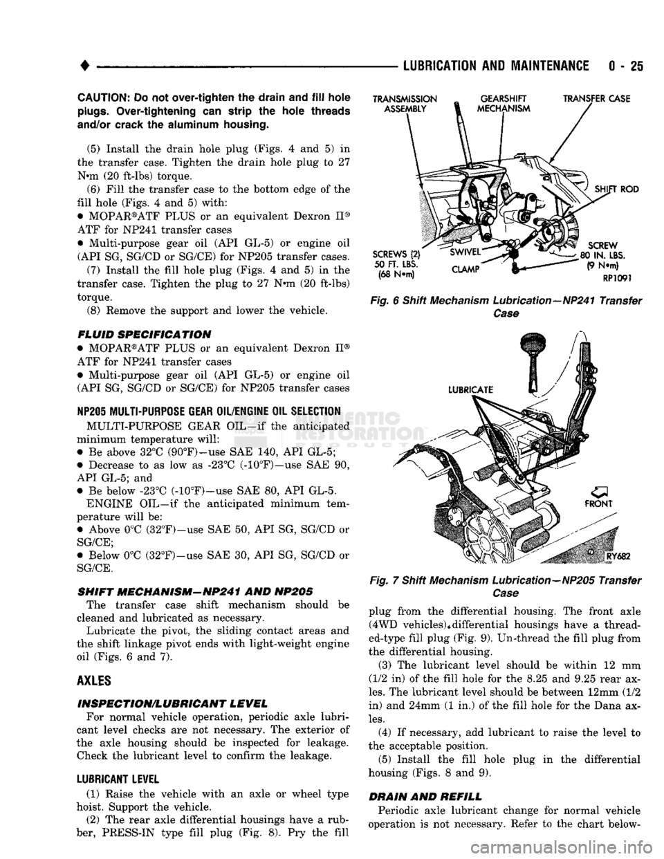
the shift linkage pivot ends with light-weight engine oil (Figs. 6 and 7).
AXLES
INSPECTION/LUBRICANT LEVEL For normal vehicle operation, periodic axle lubri
cant level checks are not necessary. The exterior of
the axle housing should be inspected for leakage. Check the lubricant level to confirm the leakage.
LUBRICANT LEVEL
(1) Raise the vehicle with an axle or wheel type
hoist. Support the vehicle.
(2) The rear axle differential housings have a rub
ber, PRESS-IN type fill plug (Fig. 8). Pry the fill
TRANSMISSION
ASSEMBLY
GEARSHIFT
MECHANISM TRANSFER CASE
SCREWS
(2)
50
FT. LBS.
(68 N*m)
CLAMP
SHIFT
ROD
SCREW
80 IN.
LBS.
(9 N*m)
RP1091
Fig.
6 Shift
Mechanism
Lubrication—NP241 Transfer
Case
Fig.
RY682
7 Shift
Mechanism
Lubrication—NP205 Transfer
Case
plug from the differential housing. The front axle (4WD vehicles)*differential housings have a thread
ed-type fill plug (Fig. 9). Un-thread the fill plug from
the differential housing.
(3) The lubricant level should be within 12 mm
(1/2 in) of the fill hole for the 8.25 and 9.25 rear ax
les.
The lubricant level should be between 12mm (1/2
in) and 24mm (1 in.) of the fill hole for the Dana ax
les.
(4) If necessary, add lubricant to raise the level to
the acceptable position.
(5) Install the fill hole plug in the differential
housing (Figs. 8 and 9).
DRAIN
AND
REFILL
Periodic axle lubricant change for normal vehicle
operation is not necessary. Refer to the chart below-
Page 47 of 1502
0
- 28
LUBRICATION
AND
MAINTENANCE
•
CHASSIS AND BODY
page
Body
Component Mechanisms
32
Front
Suspension
Ball
Joints
28
Front
Wheel Bearings
29
Headlamps
32
Lower
and
Upper Suspension
Arm
Bushings
.... 30
Manual
Steering Gear
28
STEERING
LINKAGE
INSPECTION When
a
vehicle
is
raised
for
maintenance under
the vehicle,
all
steering components should
be
checked.
LUBRICATION SCHEDULE The steering linkage
is
lubricated with
a
chassis
lubricant. However,
it is
recommended that
the
link
age
be
inspected
and
lubricated after each:
•
24 000 km
(15,000 miles) interval
or
every
6
months,
for 2WD
vehicles subject
to the
LIGHT
DUTY CYCLE Maintenance Schedule
•
9 600 km
(6,000 miles) interval
or
every
6
months,
for
2WD
vehicles subject
to the
HEAVY DUTY
CY
CLE Maintenance Schedule
•
12 000 km
(7,500 miles) interval
or
every
6
months,
for 4WD
vehicles subject
to the
LIGHT DUTY CYCLE Maintenance Schedule
•
9 600 km
(6,000 miles) interval
or
every
6
months,
for
4WD
vehicles subject
to the
HEAVY DUTY
CY
CLE Maintenance Schedule.
LUBRICATION (1) Inspect
the
steering linkage
for
looseness
and
excessive wear. (2) Replace,
all
ruptured seals
and
damaged steer
ing linkage components. Damaged seals should
be re
placed
to
prevent leakage
and
contamination
of the
lubricant.
CAUTION:
Use
care
to
prevent lubricant from
con
tacting
the
brake rotors.
(3) Lubricate
the
steering linkage:
• Clean
the
Zerk type lubrication fittings
on the tie-
rod
and
center link ball-stud ends
• Lubricate
the
ball studs with MOPAR®Multi-Mile- age Lubricant
• Wipe
the
excess lubricant from
the
exterior sur
faces
of the
ball joints
page
Power
Brake System
30
Power
Steering System
. . 29
Rear
Wheel Bearings
30
Speedometer Cable
33
Steering Linkage
28
Tires
32
FRONT
SUSPENSION
BALL JOINTS
INSPECTION When
a
vehicle
is
raised
for
lubrication/general
maintenance,
the
ball joints should
be
inspected.
LUBRICATION SCHEDULE The front suspension ball joints
are
lubricated dur
ing manufacture with
a
long-life chassis lubricant.
However,
it is
recommended that
the
ball joints
be
inspected
and the
studs lubricated:
•
At
each
36 000 km
(22,500 miles) interval
or
every
2 years,
for
vehicles subject
to the
LIGHT DUTY
CY
CLE Maintenance Schedule
•
At
each
9 600 km
(6,000 miles) interval
or
every
2
years,
for
vehicles subject
to the
HEAVY DUTY
CY
CLE Maintenance Schedule.
4WD vehicles that
are
frequently driven
off-
road should
be
lubricated
at
every engine
oil
change.
LUBRICATION (1) Inspect
the
front suspension. Examine
the
ball
studs
for
looseness
and
excessive wear. (2) Replace
all
torn ball-stud seals
and
damaged
ball joints. Damaged seals should
be
replaced
to
pre vent leakage
and
contamination.
CAUTION:
Use
care
to
prevent lubricant from
con
tacting
the
brake rotors.
(3) Lubricate
the
ball studs:
• Clean
the
Zerk type lubrication fittings
on the
ball-stud ends
• Lubricate
the
ball studs with MOPAR®Multi-Mile-age Lubricant
• Wipe
the
excess lubricant from
the
exterior sur
faces
of the
ball joints
MANUAL
STEERING
GEAR
LUBRICATION Manual steering gears
are
permanently lubricated
during manufacture. Periodic lubrication
is not
nec
essary.
Page 48 of 1502
•
LUBRICATION
AND
MAINTENANCE
0 - 29
POWER STEERING SYSTEM
SERVICE SCHEDULE
FLUID
LEWEL
WARNING.
THE
POWER
STEERING
FLUID LEVEL
SHOULD
ALWAYS
BE
CHECKED
WITH THE EN
GINE
OFF TO
PREVENT
PERSONAL
INJURY.
The power steering fluid should be checked when
ever the engine is being serviced for other reasons. Clean the outside of the cap before removing. The
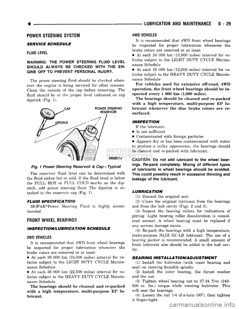
fluid should be at the proper level indicated on cap dipstick (Fig. 1).
Fig.
1
Power
Steering Reservoir & Cap—Typical
The reservoir fluid level can be determined with
the fluid either hot or cold. If the fluid level is below
the FULL HOT or FULL COLD marks on the dip stick, add power steering fluid. The dipstick is at
tached to the reservoir cap (Fig. 1).
FLUID SPECIFICATION MOPAR03)Power Steering Fluid is highly recom
mended.
FRONT
WHEEL BEARINGS
INSPECTION/LUBRICATION SCHEDULE
2WD
VEHICLES
It is recommended that 2WD front wheel bearings
be inspected for proper lubrication whenever the
brake rotors are removed or at least: • At each 39 000 km (24,000 miles) interval for ve
hicles subject to the LIGHT DUTY CYCLE Mainte nance Schedule • At each 36 000 km (22,500 miles) interval for ve
hicles subject to the HEAVY DUTY CYCLE Mainte nance Schedule The bearings should be cleaned and re-packed
with a high temperature, multi-purpose EP lu
bricant.
4WD
VEHICLES
It is recommended that 4WD front wheel bearings
be inspected for proper lubrication whenever the
brake rotors are removed or at least:
• At each 24 000 km (15,000 miles) interval for ve
hicles subject to the LIGHT DUTY CYCLE Mainte nance Schedule
• At each 19 000 km (12,000 miles) interval for ve
hicles subject to the HEAVY DUTY CYCLE Mainte nance Schedule
For vehicles used for extensive off-road, 4WD
operation, the front wheel bearings should be in spected every 1 600 km (1,000 miles).
The bearings should be cleaned and re-packed
with a high temperature, multi-purpose EP lu
bricant whenever the disc brake rotors are re surfaced.
INSPECTION If the lubricant:
• Is not sufficient
• Contaminated with foreign particles
• Appears dry or has been contaminated with water
to produce a milky appearance, the bearings should
be cleaned and re-packed with lubricant.
CAUTION:
Do not add
lubricant
to the
wheel
bear
ings.
Re-pack completely. Mixing
of
different
types
of lubricants
in
wheel
bearings should
be
avoided.
This could possibly result
in
excessive thinning
and
leakage
of the
lubricant.
LUBRICATION (1) Discard the original seal.
(2) Clean the original lubricant from the bearings
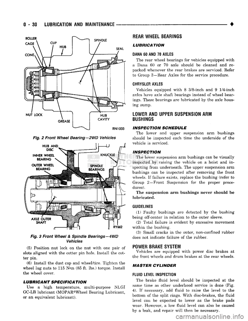
and from the hub cavity (Figs. 2 and 3).
(3) Inspect the bearing rollers for indications of
pitting. Light bearing roller discoloration is consid ered normal. A wheel bearing must be replaced if any serious damage exists.
(4) Re-pack the bearings with a high temperature,
multi-purpose NLGI GC-LB lubricant. The use of a
bearing packer is recommended. A small amount of fresh lubricant also should be added to the hub cav ity.
BEARING INSTALLA TION/ADJUSTMENT (1) Install the hub/rotor (with inner bearing and
seal) on steering knuckle spindle.
(2) Install the outer bearing, the thrust washer
and the nut.
(3) Tighten wheel bearing nut to 27-34 N^m (240-
300 in. lbs.) torque while rotating hub/rotor. This
will seat the bearings.
(4) Loosen the nut 1/4 of-a-turn (90°), then tighten
it finger-tight.
Page 49 of 1502
0 - 30
LUBRICATION
AND
MAINTENANCE
— - •
Fig.
2 Front
Wheel
Bearing—2WD Vehicles
Fig.
3 Front
Wheel
&
Spindle
Bearings—4WD
Vehicles
(5) Position nut lock on the nut with one pair of
slots aligned with the cotter pin hole. Install the cot
ter pin.
(6) Install the dust cap and wheel/tire. Tighten the
wheel lug nuts to 115 N*m (85 ft. lbs.) torque. Install
the wheel cover.
LUBRICANT SPECIFICATION
Use a high temperature, multi-purpose NLGI
GC-LB lubricant (MOPAR®Wheel Bearing Lubricant,
or an equivalent lubricant).
REAR
WHEEL BEARINGS
LUBRICATION
DANA
60
AND
70
AXLES
The rear wheel bearings for vehicles equipped with
a Dana 60 or 70 axle should be cleaned and re
packed whenever the rear brakes are serviced. Refer
to Group 3—Rear Axles for the service procedure.
CHRYSLER
AXLES
, Vehicles equipped with 8 3/8-inch and 9
1/4-inch
axles have axle shaft bearings instead of wheel bear
ings.
These bearings are lubricated by the axle hous
ing sump.
LOWER
AND UPPER
SUSPENSION
ARM
BUSHINGS
INSPECTION
SCHEDULE
The lower and upper suspension arm bushings
should be inspected each time the underside of the
vehicle is serviced.
INSPECTION
The lower suspension arm bushings can be visually
inspected by raising the vehicle on a hoist and in specting from underneath. The upper suspension arm
bushings can be inspected after removing the front wheels. If failure exists, replace the bushing (refer to Group 2—Front Suspension for the proper proce
dures).
The suspension arm bushings never should be
lubricated.
GUIDELINES
(1) Faulty bushings are detected by the bushing
being off-center in relation to the outer sleeve.
(2) Total failure is evident by excessive movement
within the bushing.
(3)
Small cracks in the outer, non-confined rubber
does not indicate failure of the rubber. '
POWER BRAKE SYSTEM
Vehicles are equipped with power disc brakes at
the front wheels and drum brakes at the rear wheels.
MASTER CYLINDER
FLUID
LEVEL INSPECTION
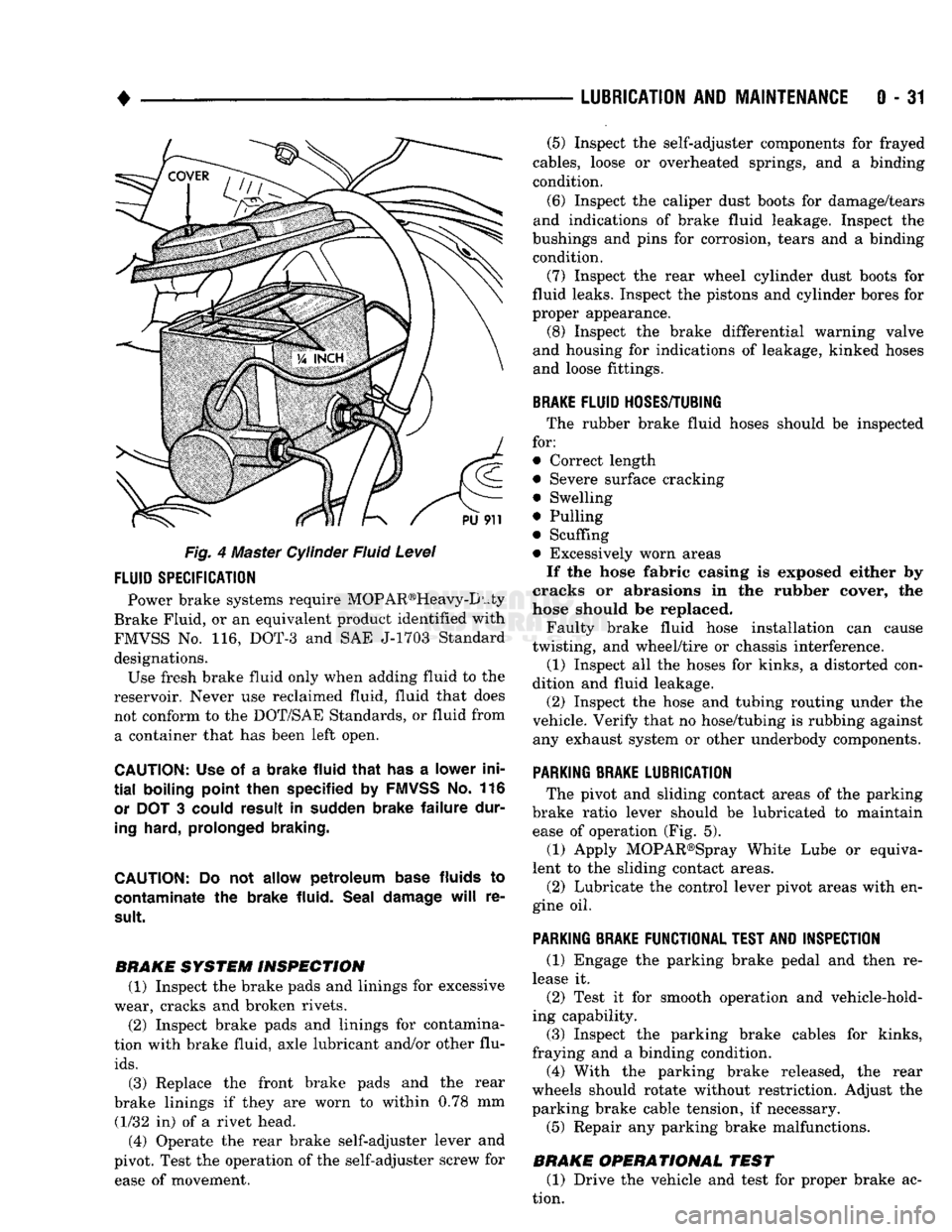
The brake fluid level should be inspected at the
same time as other underhood service is done (Fig.
4).
If necessary, add fluid to raise the level to the
bottom of the split rings. With disc-brakes, the fluid level can be expected to lower as the brake pads
wear. However, a low fluid level can also be caused
by a leak, and repair will then be necessary.
Page 50 of 1502
•
LUBRICATION
AND
MAINTENANCE
0 - 31
Fig. 4 Master Cylinder Fluid Level
FLUID
SPECIFICATION
Power brake systems require MOP AR®Heavy-D uty
Brake Fluid, or an equivalent product identified with
FMVSS No. 116, DOT-3 and SAE J-1703 Standard designations. Use fresh brake fluid only when adding fluid to the
reservoir. Never use reclaimed fluid, fluid that does not conform to the DOT/SAE Standards, or fluid from a container that has been left open.
CAUTION:
Use of a
brake fluid that
has a
lower ini
tial
boiling point then specified
by
FMVSS
No. 116
or
DOT 3
could result
in
sudden brake failure dur
ing
hard, prolonged braking.
CAUTION:
Do not
allow petroleum base
fluids
to
contaminate
the
brake fluid. Seal damage
will
re
sult.
BRAKE SYSTEM INSPECTION (1) Inspect the brake pads and linings for excessive
wear, cracks and broken rivets.
(2) Inspect brake pads and linings for contamina
tion with brake fluid, axle lubricant and/or other flu
ids.
(3) Replace the front brake pads and the rear
brake linings if they are worn to within 0.78 mm (1/32 in) of a rivet head.
(4) Operate the rear brake self-adjuster lever and
pivot. Test the operation of the self-adjuster screw for ease of movement. (5) Inspect the self-adjuster components for frayed
cables, loose or overheated springs, and a binding
condition.
(6) Inspect the caliper dust boots for damage/tears
and indications of brake fluid leakage. Inspect the
bushings and pins for corrosion, tears and a binding condition.
(7) Inspect the rear wheel cylinder dust boots for
fluid leaks. Inspect the pistons and cylinder bores for
proper appearance. (8) Inspect the brake differential warning valve
and housing for indications of leakage, kinked hoses and loose fittings.
BRAKE
FLUID
HOSES/TUBING
The rubber brake fluid hoses should be inspected
for:
• Correct length
• Severe surface cracking
• Swelling
• Pulling
• Scuffing
• Excessively worn areas If the hose fabric casing is exposed either by
cracks or abrasions in the rubber cover, the
hose should be replaced.
Faulty brake fluid hose installation can cause
twisting, and wheel/tire or chassis interference.
(1) Inspect all the hoses for kinks, a distorted con
dition and fluid leakage. (2) Inspect the hose and tubing routing under the
vehicle. Verify that no hose/tubing is rubbing against any exhaust system or other underbody components.
PARKING
BRAKE
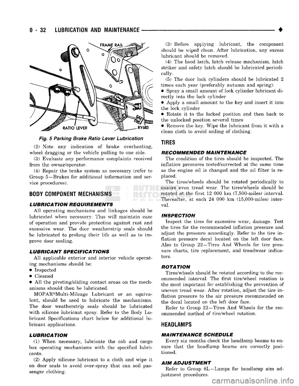
LUBRICATION
The pivot and sliding contact areas of the parking
brake ratio lever should be lubricated to maintain ease of operation (Fig. 5).
(1) Apply MOPAR®Spray White Lube or equiva
lent to the sliding contact areas.
(2) Lubricate the control lever pivot areas with en
gine oil.
PARKING
BRAKE
FUNCTIONAL
TEST
AND
INSPECTION
(1) Engage the parking brake pedal and then re
lease it. (2) Test it for smooth operation and vehicle-hold
ing capability.
(3) Inspect the parking brake cables for kinks,
fraying and a binding condition. (4) With the parking brake released, the rear
wheels should rotate without restriction. Adjust the
parking brake cable tension, if necessary.
(5) Repair any parking brake malfunctions.
BRAKE OPERATIONAL TEST (1) Drive the vehicle and test for proper brake ac
tion.
Page 51 of 1502
0
- 32
LUBRICATION
AND
MAINTENANCE
•
Fig.
5 Parking Brake Ratio Lever Lubrication (2) Note any indication of brake overheating,
wheel dragging or the vehicle pulling to one side.
(3) Evaluate any performance complaints received
from the owner/operator. (4) Repair the brake system as necessary (refer to
Group 5—Brakes for additional information and ser
vice procedures).
BODY
COMPONENT
MECHANISMS
LUBRICATION REQUIREMENTS
All operating mechanisms and linkages should be
lubricated when necessary. This will maintain ease of operation and provide protection against rust and
excessive wear. The door weatherstrip seals should
be lubricated to prolong their life as well as to im prove door sealing.
LUBRICANT SPECIFICATIONS
All applicable exterior and interior vehicle operat
ing mechanisms should be:
• Inspected • Cleaned
• All the pivoting/sliding contact areas on the mech anisms should then be lubricated.
MOPAR®Multi-Mileage Lubricant or an equiva
lent, should be used to lubricate the mechanisms.
The door weatherstrip seals should be lubricated
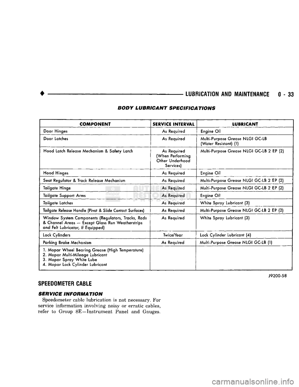
with silicone lubricant spray. Refer to the Body Lu
bricant Specifications chart below for additional lu
bricant applications.
LUBRICATION
(1) When necessary, lubricate the cab and cargo
box operating mechanisms with the specified lubri
cants.
(2) Apply silicone lubricant to a cloth and wipe it
on door seals to avoid over-spray that can soil pas
senger clothing. (3) Before applying lubricant, the component
should be wiped clean. After lubrication, any excess
lubricant should be removed.
(4) The hood latch, latch release mechanism, latch
striker and safety latch should be lubricated periodi
cally.
(5) The door lock cylinders should be lubricated 2
times each year (preferably autumn and spring): • Spray a small amount of lock cylinder lubricant di
rectly into the lock cylinder
• Apply a small amount to the key and insert it into
the lock cylinder • Rotate it to the locked position and then back to
the unlocked position several times
• Remove the key. Wipe the lubricant from it with a
clean cloth to avoid soiling of clothing.
TIRES
RECOMMENDED MAINTENANCE
The condition of the tires should be inspected. The
inflation pressures tested/corrected at the same time as the engine oil is changed and the oil filter is re
placed.
The tires/wheels should be rotated periodically to
ensure even tread wear. The tires/wheels should be
rotated at the first 12 000 km (7,500-miles) interval.
Thereafter, at each 24 000 km (15,000-miles) inter
val.
INSPECTION
Inspect the tires for excessive wear, damage. Test
the tires for the recommended inflation pressure and adjust the pressure accordingly. Refer to the tire in
flation pressure decal located on the left door face. Also to Group 22—Tires And Wheels for tire pressure charts, tire replacement, and treadwear indica
tors.
ROTATION
Tires/wheels should be rotated according to the rec
ommended interval. The first tire/wheel rotation is
the most important for establishing the prevention of uneven tread wear. After rotation, adjust the tire in
flation pressure to the air pressure recommended on
the decal located on the left door face.
Refer to Group 22—Tires And Wheels for the rec
ommended method of tire/wheel rotation.
HEADLAMPS
MAINTENANCE SCHEDULE
Every six months check the headlamp beams to en
sure that the headlamp beams are correctly posi
tioned.
AIM
ADJUSTMENT
Refer to Group 8L—Lamps for headlamp aim ad
justment procedures.
Page 52 of 1502
•
LUBRICATION
AND
MAINTENANCE
0 - 33 BODY LUBRICANT SPECIFICATIONS
COMPONENT
SERVICE
INTERVAL
LUBRICANT
Door
Hinges
As
Required
Engine
Oil
Door
Latches
As
Required Multi-Purpose Grease
NLGI
GC-LB
(Water
Resistant)
(1)
Hood
Latch Release Mechanism
&
Safety Latch
As
Required
(When Performing Other Underhood Services) Multi-Purpose Grease
NLGI
GC-LB
2
EP
(2)
Hood
Hinges
As
Required
Engine
Oil
Seat Regulator
&
Track Release Mechanism
As
Required Multi-Purpose Grease
NLGI
GC-LB
2
EP
(2)
Tailgate Hinge
As
Required Multi-Purpose Grease
NLGI
GC-LB
2
EP
(2)
Tailgate Support Arms
As
Required
Engine
Oil
Tailgate Latches
As
Required
White
Spray Lubricant
(3)
Tailgate Release Handle (Pivot & Slide Contact Surfaces)
As
Required Multi-Purpose Grease
NLGI
GC-LB
2
EP
(2)
Window System Components (Regulators, Tracks,
Rods
&
Channel Areas — Except
Glass
Run Weatherstrips
and
Felt
Lubricator,
if
Equipped)
As
Required
White
Spray Lubricant
(3)
Lock
Cylinders Twice/Year
Lock
Cylinder Lubricant
(4)
Parking Brake Mechanism
As
Required Multi-Purpose Grease
NLGI
GC-LB
(1)
1.
Mopar
Wheel
Bearing Grease (High
Temperature)
2. Mopar Multi-Mileage Lubricant 3. Mopar Spray
White
Lube
4. Mopar Lock Cylinder Lubricant
J9200-58
SPEEDOMETER
CABLE
SERVICE INFORMATION Speedometer cable lubrication is not necessary. For
service information involving noisy or erratic cables,
refer to Group 8E—Instrument Panel and Gauges.
Page 54 of 1502
•
FRONT SUSPENSION
AND
AXLE
2 - 1
CONTENTS
page
FRONT SUSPENSION—2WD VEHICLES
......
7
FRONT SUSPENSION—4WD VEHICLES
14
FRONT WHEEL
ALIGNMENT
...............
3
GENERAL INFORMATION
1
page
MODEL
44
FRONT AXLE
17
MODEL
80
FRONT AXLE
49
TORQUE SPECIFICATIONS
75
GENERAL
INFORMATION
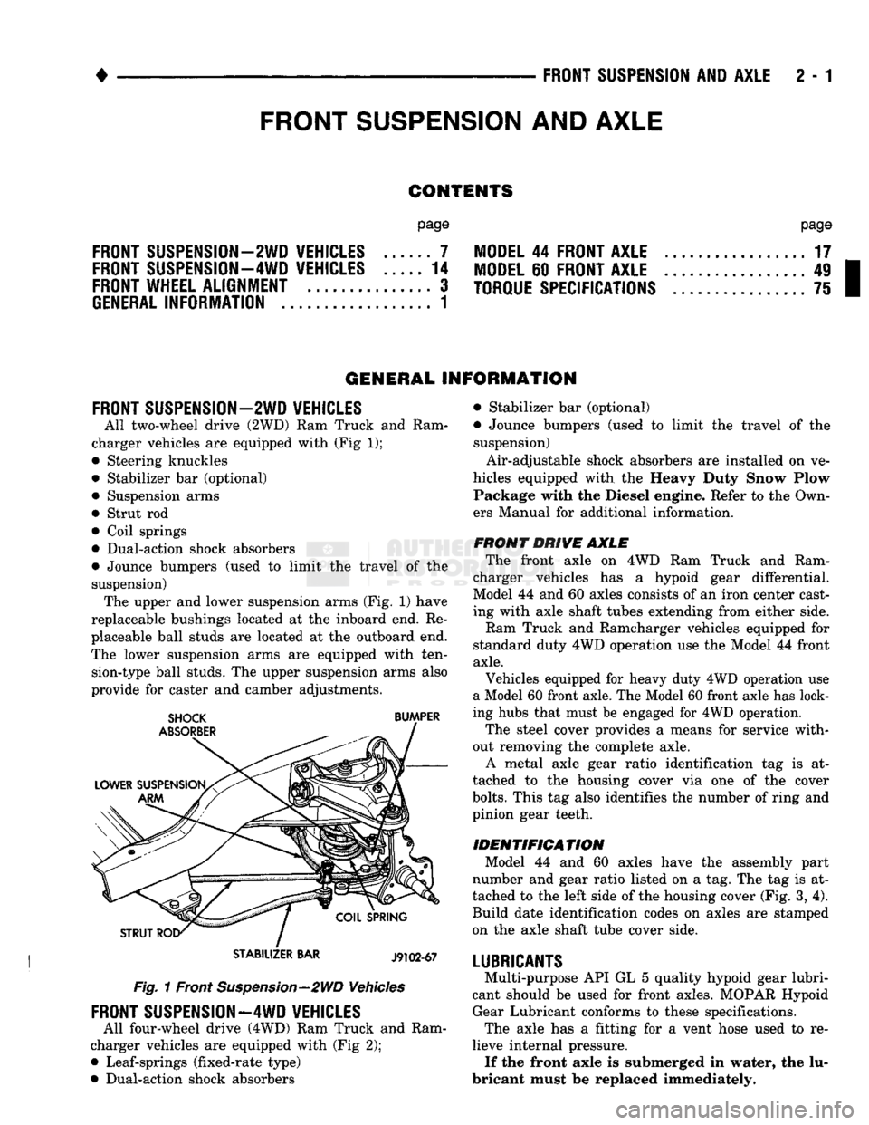
FRONT SUSPENSION—2WD VEHICLES
All two-wheel drive (2WD)
Ram
Truck
and
Ram
charger vehicles
are
equipped with (Fig
1);
• Steering knuckles
• Stabilizer
bar
(optional) • Suspension arms
• Strut
rod
• Coil springs
• Dual-action shock absorbers
• Jounce bumpers (used
to
limit
the
travel
of the
suspension) The upper and lower suspension arms (Fig.
1)
have
replaceable bushings located
at the
inboard end.
Re
placeable ball studs
are
located
at
the
outboard end.
The lower suspension arms
are
equipped with ten sion-type ball studs. The upper suspension arms also
provide
for
caster
and
camber adjustments.
STABILIZER
BAR
J9102-67
Fig. 1 Front Suspension—2WD Vehicles
FRONT SUSPENSION—4WD VEHICLES
All four-wheel drive (4WD) Ram Truck
and
Ram
charger vehicles
are
equipped with (Fig
2);
• Leaf-springs (fixed-rate type)
• Dual-action shock absorbers • Stabilizer
bar
(optional)
• Jounce bumpers (used
to
limit
the
travel
of the
suspension)
Air-adjustable shock absorbers
are
installed
on
ve
hicles equipped with
the
Heavy Duty Snow Plow Package with
the
Diesel engine. Refer
to
the Own
ers Manual
for
additional information.
FRONT DRIVE AXLE The front axle
on 4WD Ram
Truck
and
Ram
charger vehicles
has a
hypoid gear differential.
Model
44
and
60
axles consists
of
an iron center cast
ing with axle shaft tubes extending from either side.
Ram Truck
and
Ramcharger vehicles equipped
for
standard duty 4WD operation use
the
Model
44
front
axle.
Vehicles equipped
for
heavy duty 4WD operation
use
a Model 60 front axle. The Model 60 front axle has lock
ing hubs that must
be
engaged
for
4WD operation.
The steel cover provides
a
means
for
service with
out removing
the
complete axle. A metal axle gear ratio identification
tag is at
tached
to the
housing cover
via one of the
cover
bolts.
This
tag
also identifies
the
number
of
ring and
pinion gear teeth.
IDENTIFICATION Model
44 and 60
axles have
the
assembly part
number
and
gear ratio listed
on a
tag. The
tag
is at
tached
to
the
left side
of
the housing cover (Fig.
3,
4).
Build date identification codes
on
axles
are
stamped
on
the
axle shaft tube cover side.
LUBRICANTS
Multi-purpose API
GL
5
quality hypoid gear lubri
cant should
be
used
for
front axles. MOPAR Hypoid Gear Lubricant conforms
to
these specifications. The axle
has a
fitting
for a
vent hose used
to re
lieve internal pressure. If the front axle
is
submerged
in
water,
the
lu
bricant must
be
replaced immediately.
FRONT
SUSPENSION
AND
AXLE