1993 DODGE TRUCK wheel
[x] Cancel search: wheelPage 130 of 1502
•
REAR
SUSPENSION
AND
AXLE
3 - 1
CONTENTS
page
8
3/8 and 9 1/4
AXLE
11
GENERAL
INFORMATION
1
MODEL
60 and 70
AXLES
29
POWER-LOK DIFFERENTIAL
55
REAR
SUSPENSION—2WD
and
4WD VEHICLES
3
page
SERVICE
DIAGNOSIS
6
SPECIFICATIONS
27
SURE-GRIP
DIFFERENTIAL SERVICE
28
TORQUE SPECIFICATIONS
59
TRAC-LOK DIFFERENTIAL
51
GENERAL INFORMATION
SUSPENSION
Ram Truck rear suspensions
are
comprised
of;
• Drive axle
• Leaf springs
• Dual-action shock absorbers
• Jounce bumpers (used
to
limit
the
travel
of the
suspension) All
Ram
Truck
and
Ramcharger vehicles
are
equipped with leaf-type rear springs.
The
springs
have
a
one-piece, rubber bushing pressed into their main leaf front
eye.
Model
150 and
Ramcharger
ve
hicles
are
equipped with
a
fixed-rate type leaf spring. Progressive-rate type rear leaf springs
are
standard equipment
for all
Model
250 and 350
vehicles.
AXLES
The
8 3/8, 9
1/4-Inch
,
Model
60 and 70
axle hous
ings consist
of a
cast iron center section. They also
have
two
steel axle shaft tubes that
are
pressed into and welded
to the
differential housing. The removable, stamped steel cover provides
a
means
for
inspection
and
service without removing
the complete axle from
the
vehicle. Both axle types
are
equipped with
a
remote vent
fitting. A small, stamped metal axle gear ratio identifica
tion
tag is
attached
to the
housing cover. The rear wheel anti-lock (RWAL) brake speed sen
sor
is
attached
to the top,
forward exterior
of the dif
ferential housing.
A
seal
is
located between
the
sensor
and the
wire harness connector.
The
seal
must
be
in-plaee when
the
wire connector
is
connected
to the
sensor.
The
RWAL brake exciter
ring
is
press-fitted onto
the
differential case against
the flange. A rear axle equipped with
a
Sure-Grip differential
is optionally available
for
both
Ram
Truck
and
Ram
charger vehicles.
The
Sure-Grip
has a
two-piece case
that
is
interchangeable with
a
standard differential.
A limited-slip differential
is
optional
on
Model
60,
and
70
rear axles.
The
Model
60
uses
the
Trac-Lok
differential
and the
Model
70
uses
the
Power-Lok
dif
ferential.
The
Trac-Lok differential uses
a
one-piece case while
the
Power-Lok differential uses
a two-
piece case. Both
use the
same internal components
as
a standard differential, plus
two
clutch disc packs.
IDENTIFICATION The axle differential covers
can be
used
for
identi
fication (Fig.
1, 2, 3).
Model
60
axle
has the
assembly part number
and
gear ratio listed
on a tag. The tag is
attached
to the
left side
of the
housing cover
(Fig. 3).
Build date
identification codes
on
axles
are
stamped
on the
axle
shaft tube cover side.
LUBRICANTS
Multi-purpose, hypoid gear lubricant should
be
used
for
rear axles with either
a
standard
or a
Sure- Grip differential.
The
lubricant should have MIL-L-
2105-B
and by API GL 5
quality specifications.
MOPAR Hypoid Gear Lubricant conforms
to
both
of
these specifications.
In
addition,
4
ounces
of
Hypoid Additive must
be
included with
a
re-fill
for
Sure-Grip differentials.
If
the
rear axle
is
submerged
in
water,
the lu
bricant must
be
replaced immediately. Avoid axle failure resulting from water contamination
of
the
lubricant.
REAR
SUSPENSION
AND
AXLE
Page 135 of 1502
3
- 6
REAR SUSPENSION
AND
AXLE
•
NUT PIPE
SOCKET
WRENCH
(DRIVER)
FLAT
THREADED
WASHER
ROD
J8917-20
Fig.
6
Spring
Eye
Bushing
Removal
(3) Align
the
bushing with
the
spring
eye and
tighten
the nut
located
at the
socket wrench
end of
the threaded
rod.
Tighten until
the
bushing
is
forced into
the
spring
eye.
The bushing must
be
centered
in the
spring
eye.
The
ends
of the
bushing must
be
flush
or
slightly recessed within
the end
surfaces
of the
spring
eye.
8ERW1GE DIAGNOSIS
INDEX
page
Driveline
Snap
8
Gear
and
Bearing Noise
7
General
Information
6
Limited
Slip
Differential
8
page
Low Speed Knock
.........................
8
Rear
Axle
Alignment
.......................
7
Tire
Noise
7
Vibration
8
GENERAL INFORMATION
Axle bearing problem conditions
are
usually caused
by: • Insufficient
or
incorrect lubricant
• Foreign matter/water contamination
• Incorrect bearing preload torque adjustment When serviced,
the
bearings must
be
cleaned thor
oughly. They should
be
dried with lint-free shop tow
els.
Never
dry
bearings with compressed
air.
This will overheat them
and
brinell
the
bearing surfaces. This will result
in
noisy operation after
repair. Axle gear problem conditions
are
usually
the
result
of:
• Insufficient lubrication
• Incorrect
or
contaminated lubricant
• Overloading (excessive engine torque)
• Incorrect clearance
or
backlash adjustment Insufficient lubrication
is
usually
the
result
of a
housing cover leak.
It can
also
be
from worn axle shaft
or
pinion gear seals. Check
for
cracks
or
porous
areas
in the
housing
or
tubes.
Using
the
wrong lubricant will cause overheating
and gear failure. Gear tooth cracking
and
bearing
spalling
are
indicators
of
this.
Axle component breakage
is
most often
the
result
of:
• Severe overloading
• Insufficient lubricant
• Incorrect lubricant • Improperly tightened components
Common causes
of
overloading
is
from full-throttle
acceleration. Overloading occurs when towing
heavier than normal loads. Component breakage
can
occur when
the
wheels
are
spun excessively. Insuffi
cient
or
incorrect lubricants contribute
to
breakage
through overheating. Loose differential components can also cause breakage. Incorrect bearing preload
or
gear backlash will
not
result
in
component breakage. Mis-adjustment will
produce enough noise
to
cause service repair before
a
Page 136 of 1502
•
RfAR SUSPENSION
AND
AXLE
3 - 7 failure occurs. If a mis-adjustment condition is not
corrected, component failure can result.
REAR
AXLE ALIGNMENT
MEASUREMENT The following procedure can be used to determine
if abnormal rear tire tread wear is the result of a
bent or deformed rear axle shaft.
(1) Raise both rear wheels off the surface with a
frame contact hoist. (2) Attach a one-inch long piece of masking tape at
the center of each tire tread for use as reference marks.
(3) Rotate the rear wheels until both reference
marks face the front of the vehicle. Measure the dis
tance between the outside edges of the two pieces of
tape.
Record this measurement as the front of tire (FTR) measurement.
(4) Rotate the rear wheels until both reference
marks face the rear of the vehicle. Measure the dis
tance between the outside edges of the two pieces of
tape.
Record this measurement as the rear of tire (RTR) measurement.
(5) Subtract the (RTR) measurement from the
(FTR) measurement to obtain the amount of wheel
toe.
The acceptable rear wheel toe-in position is 1/16 inch (1.6 mm) to 3/16 inch (4.8 mm) toe-out.
(6) Rotate the rear wheels until the reference
marks are facing downward. Measure the distance
between the outside edges of the two pieces of tape. Record this measurement as the bottom of tire (BTR)
measurement.
(7) Average the (FTR) and the (RTR) distance
measurements. Subtract the (BTR) measurement
from this average distance to obtain the camber. The acceptable amount of camber is 1/16 inch to 3/32 inch
(1.6 to 2.4 mm).
(FTR + RTR) DIVIDED BY 2 (TWO) MINUS
BTR EQUALS CAMBER
If the (BTR) distance measurement is less than
the average FTR and RTR distance measure
ment, the camber will be positive ( + ). If the (BTR) distance measurement is greater than the average FTR and RTR distance, the camber will
be negative ( - ).
If the toe position or camber is not acceptable, a
bent or deformed rear axle shaft is most likely the cause.
TIRE
NOISE
Check tires that are damaged, unbalanced, incor
rectly inflated. Tires that have deep treads can emit sounds like axle noise. Differentiate between tire and
axle noise during a road test. Tire noise will usually vary with different road
conditions. Tire noise is sensitive to inflation pres
sure.
The pitch of tire noise changes when the vehi
cle speed is varied.
Drive the vehicle over different road surfaces. Note
the changes in the noise. If the noise changes, the
tires are the source of the noise.
Refer to Group 22, Wheels and Tires for additional
information.
GEAR
AND BEARING NOISE
GEAR
NOISE
Axle gear noise can be caused by insufficient lubri
cant. Incorrect backlash, tooth contact, or worn/dam aged gears can cause noise.
Gear noise usually happens at a specific speed
range. The range is 30 to 40 mph, or above 50 mph.
The noise can also occur during a specific type of driving condition. These conditions are, acceleration,
deceleration, coast, or constant load.
When road testing, accelerate the vehicle to the
speed range where the noise is the greatest. Shift
out-of-gear and coast through the peak-noise range.
If the noise stops or changes greatly, check for
insuf
ficient lubricant. Incorrect ring gear backlash, or gear damage can cause noise changes.
Differential side and pinion gears can be checked
by turning the vehicle. They usually do not cause noise in straight-ahead driving. These gears are
loaded during vehicle turns. If noise does occur dur
ing vehicle turns, the side or pinion gears could be
worn or damaged. A worn pinion gear mate shaft can also cause a snapping or a knocking noise.
BEARING NOISE
The axle shaft, differential and pinion gear bear
ings can all produce noise when worn or damaged.
Bearing noise can be either a whining, or a growling sound.
Pinion gear bearings have a constant-pitch noise.
This noise changes only with vehicle speed. Pinion
bearing noise will be higher because it rotates at a faster rate. Drive the vehicle and load the differen
tial.
If bearing noise occurs the pinion rear bearing is the source of the noise. If the bearing noise is heard during a coast, front bearing is the source.
Worn, damaged differential bearings usually pro
duce a low pitch noise. Differential bearing noise is
similar to pinion bearing. The pitch of differential
bearing noise is also constant and varies only with vehicle speed.
Axle shaft bearings produce noise and vibration
when worn or damaged. The noise generally changes
when the bearings are loaded. Road test the vehicle. Turn the vehicle sharply to the left and to the right.
This will load the bearings and change the noise
Page 137 of 1502
3
- 8
REAR SUSPENSION
AND
AXLE
• level. Where axle bearing damage is slight, the noise
is usually not noticeable at speeds above 30 mph.
LOW SPEED KNOCK
Low speed knock is generally caused by a worn
U-joint or by worn side-gear thrust washers. A worn
pinion gear shaft bore will also cause low speed knock.
VIBRATION
Vibration at the rear of the vehicle is usually
caused by a:
• Damaged drive shaft
• Missing drive shaft balance weight
• Worn, out-of-balance wheel and tires
• Loose wheel lug nuts
• Worn U-joint • Loose spring U-bolts
• Loose/broken rear springs or shackles
• Damaged axle shaft bearings
• Loose pinion gear nut
• Excessive pinion yoke run out
• Bent axle shaft Check for loose or damaged front-end components
or engine/transmission mounts. These components
can contribute to what appears to be a rear-end vi
bration. Do not overlook engine accessories, brackets and drive belts. All driveline components should be examined be
fore starting any repair. Refer to Group 22, Wheels and Tires for additional
information.
DRIVELINE SNAP
A snap or clunk noise when the vehicle is shifted
into gear (or the clutch engaged), can be caused by: • High engine idle speed
• Loose engine/transmission/transfer case mounts
9
Worn U-joints
• Loose spring shackles or U-bolts
• Loose pinion gear nut and yoke
• Excessive ring gear backlash
• Excessive differential side gear-to-case clearance A worn bushing in the transmission extension
housing can also cause noise. The source of a snap or a clunk noise can be deter
mined with the assistance of a helper. Raise the ve
hicle on a hoist with the wheels free to rotate. Instruct the helper to shift the transmission into gear. Listen for the noise, a mechanics stethoscope is
helpful in isolating the source of a noise.
LIMITED
SLIP DIFFERENTIAL
Under normal traction conditions, engine torque is
divided evenly. With low-traction surfaces, engine
torque is transferred to the wheel with the most tire
traction. When diagnosing a limited-slip differential
problem condition, the wheel with the least traction can continue spinning. The most common problem is a chatter noise when
turning corners. Check for incorrect or contaminated lubricant. Replace the gear lubricant if necessary.
• With Sure-Grip differentials add a container of
MOPAR® Hypoid Gear Additive This will correct the condition in most instances. If
the chatter persists, clutch damage could have oc curred. After changing the lubricant, drive the vehicle and
make 10 to 12 slow, figure-eight turns. This maneu
ver will pump lubricant through the clutches.
Page 138 of 1502
REAR
SUSPENSION
AND
AXLE
3 - 9
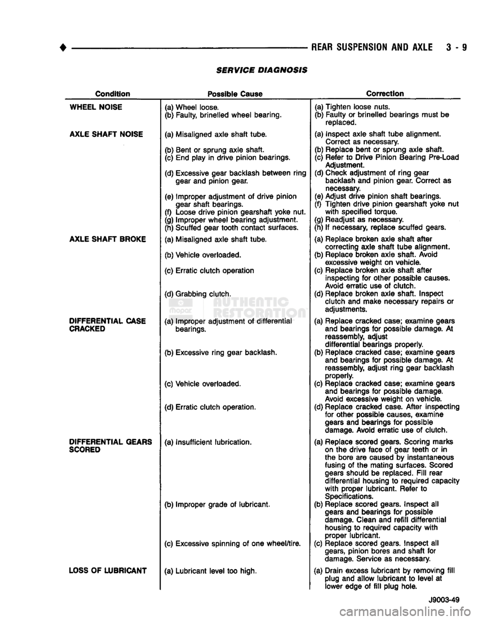
SERVICE DIAGNOSIS
Condition
Possible
Cause
Correction
WHEEL
NOISE
AXLE
SHAFT
NOISE
AXLE
SHAFT
BROKE
DIFFERENTIAL
CASE
CRACKED
DIFFERENTIAL
GEARS
SCORED
LOSS
OF
LUBRICANT
(a) Wheel loose.
(b) Faulty, brinelled
wheel
bearing.
(a) Misaligned axle shaft tube.
(b) Bent or sprung axle shaft. (c) End play in drive pinion bearings.
(d) Excessive gear backlash
between
ring
gear
and pinion gear.
(e) Improper adjustment of drive pinion
gear
shaft bearings.
(f) Loose drive pinion gearshaft yoke nut.
(g) Improper
wheel
bearing adjustment. (h) Scuffed gear tooth contact surfaces.
(a) Misaligned axle shaft tube.
(b) Vehicle overloaded.
(c) Erratic clutch operation
(d) Grabbing clutch.
(a) Improper adjustment of
differential
bearings.
(b) Excessive ring gear backlash.
(c) Vehicle overloaded. (d) Erratic clutch operation.
(a) Insufficient lubrication.
(b) Improper grade of lubricant.
(c) Excessive spinning of one
wheel/tire.
(a) Lubricant
level
too high. (a) Tighten loose nuts.
(b) Faulty or brinelled bearings must be
replaced.
(a) Inspect axle shaft
tube
alignment. Correct as necessary.
(b) Replace bent or sprung axle shaft.
(c) Refer to Drive Pinion Bearing Pre-Load Adjustment.
(d) Check adjustment of ring gear
backlash
and pinion gear. Correct as
necessary.
(e) Adjust drive pinion shaft bearings.
(f) Tighten drive pinion gearshaft yoke nut
with
specified torque.
(g) Readjust as necessary.
(h) If necessary, replace scuffed gears.
(a) Replace broken axle shaft
after
correcting axle shaft
tube
alignment.
(b) Replace broken axle shaft. Avoid
excessive
weight on vehicle.
(c) Replace broken axle shaft
after
inspecting for other possible
causes.
Avoid
erratic
use of clutch.
(d) Replace broken axle shaft. Inspect clutch and make necessary repairs or adjustments.
(a) Replace cracked case; examine gears and bearings for possible damage. At
reassembly,
adjust
differential
bearings properly.
(b) Replace cracked case; examine gears and bearings for possible damage. At
reassembly,
adjust ring gear backlash properly.
(c) Replace cracked case; examine gears and bearings for possible damage.
Avoid
excessive weight on vehicle.
(d) Replace cracked case.
After
inspecting for other possible
causes,
examine
gears
and bearings for possible
damage.
Avoid
erratic
use of clutch.
(a) Replace scored gears. Scoring marks
on
the drive face of gear
teeth
or in
the bore are caused by instantaneous
fusing
of the mating surfaces. Scored
gears
should be replaced.
Fill
rear
differential
housing to
required
capacity
with
proper lubricant. Refer to
Specifications.
(b) Replace scored gears. Inspect all
gears
and bearings for possible
damage.
Clean and
refill
differential
housing
to
required
capacity
with
proper lubricant.
(c) Replace scored gears. Inspect all
gears,
pinion bores and shaft for
damage.
Service as necessary.
(a) Drain excess lubricant by removing
fill
plug and allow lubricant to
level
at lower edge of
fill
plug hole.
J9003-49
Page 140 of 1502
•
REAR
SUSPENSION
AND
AXLE
3 - 11 8 3/8 and 9 1/4
AXLE
INDEX
page
Axle Shaft, Seal
and
Bearing Service
......... 11
Complete Axle Removal/Installation
16
Differential
Service
16
Information
11
INFORMATION
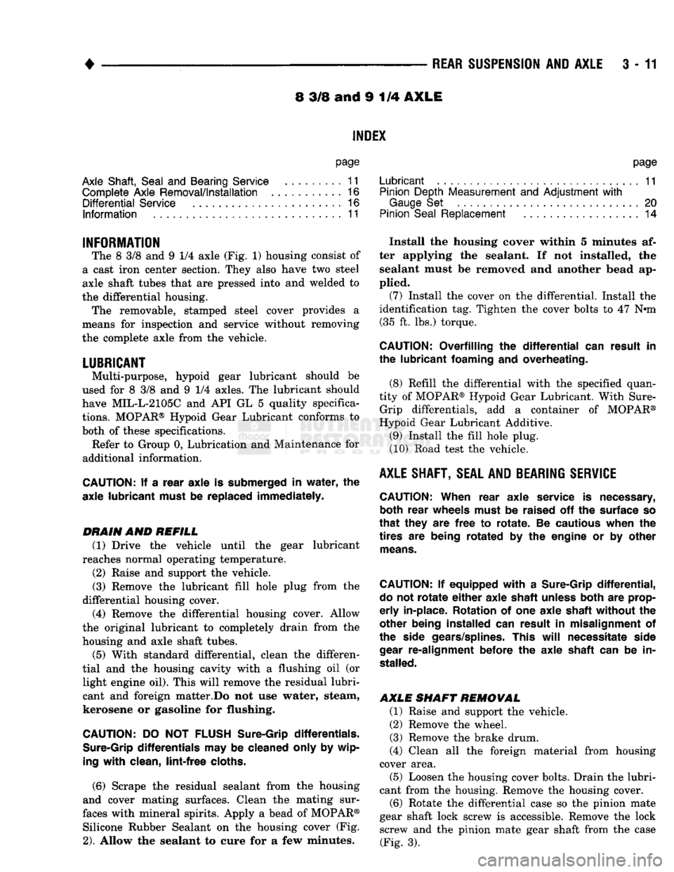
The 8 3/8 and 9 1/4 axle (Fig. 1) housing consist of
a cast iron center section. They also have two steel
axle shaft tubes that are pressed into and welded to
the differential housing. The removable, stamped steel cover provides a
means for inspection and service without removing
the complete axle from the vehicle.
LUBRICANT
Multi-purpose, hypoid gear lubricant should be
used for 8 3/8 and 9 1/4 axles. The lubricant should
have MIL-L-2105C and API GL 5 quality specifica
tions.
MOPAR® Hypoid Gear Lubricant conforms to
both of these specifications.
Refer to Group 0, Lubrication and Maintenance for
additional information.
CAUTION:
If a
rear axle
is
submerged
in
water,
the
axle lubricant must
be
replaced immediately.
DRAIN
AND
REFILL
(1) Drive the vehicle until the gear lubricant
reaches normal operating temperature.
(2) Raise and support the vehicle.
(3) Remove the lubricant fill hole plug from the
differential housing cover.
(4) Remove the differential housing cover. Allow
the original lubricant to completely drain from the
housing and axle shaft tubes. (5) With standard differential, clean the differen
tial and the housing cavity with a flushing oil (or light engine oil). This will remove the residual lubri
cant and foreign matter.Do not use water, steam,
kerosene or gasoline for flushing.
CAUTION:
DO NOT
FLUSH
Sure-Grip differentials.
Sure-Grip
differentials
may be
cleaned only
by
wip
ing
with
clean,
lint-free
cloths.
(6)
Scrape the residual sealant from the housing
and cover mating surfaces. Clean the mating sur
faces with mineral spirits. Apply a bead of MOPAR® Silicone Rubber Sealant on the housing cover (Fig.
2).
Allow the sealant to cure for a few minutes.
page
Lubricant
11
Pinion Depth Measurement
and
Adjustment
with
Gauge
Set 20
Pinion
Seal
Replacement
14
Install the housing cover within 5 minutes af
ter applying the sealant. If not installed, the sealant must be removed and another bead ap
plied. (7) Install the cover on the differential. Install the
identification tag. Tighten the cover bolts to 47 N#m (35 ft. lbs.) torque.
CAUTION:
Overfilling
the
differential
can
result
in
the lubricant foaming
and
overheating.
(8) Refill the differential with the specified quan
tity of MOPAR® Hypoid Gear Lubricant. With Sure- Grip differentials, add a container of MOPAR®
Hypoid Gear Lubricant Additive.
(9) Install the fill hole plug.
(10) Road test the vehicle.
AXLE
SHAFT, SEAL AND BEARING
SERVICE
CAUTION:
When rear axle service
is
necessary, both rear wheels must
be
raised
off the
surface
so
that
they
are
free
to
rotate.
Be
cautious when
the
tires
are
being rotated
by the
engine
or by
other
means.
CAUTION:
If
equipped
with
a
Sure-Grip
differential,
do
not
rotate
either
axle shaft unless both
are
prop
erly
in-place. Rotation
of one
axle shaft without
the
other being installed
can
result
in
misalignment
of
the side gears/splines. This
will
necessitate side
gear
re-alignment before
the
axle shaft
can be in
stalled.
AXLE SHAFT REMOVAL
(1) Raise and support the vehicle.
(2) Remove the wheel.
(3) Remove the brake drum.
(4) Clean all the foreign material from housing
cover area.
(5) Loosen the housing cover bolts. Drain the lubri
cant from the housing. Remove the housing cover.
(6)
Rotate the differential case so the pinion mate
gear shaft lock screw is accessible. Remove the lock screw and the pinion mate gear shaft from the case (Fig. 3).
Page 143 of 1502
3
- 14
REAR SUSPENSION
AND
AXLE
3
- 18
REAR SUSPENSION Fig.
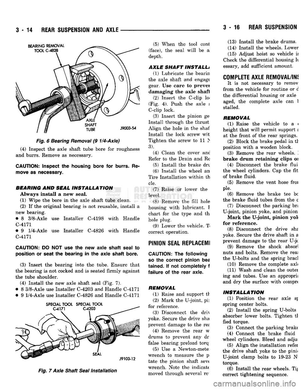
6 Bearing
Removal
(9
1/4-Axle)
(4) Inspect the axle shaft tube bore for roughness
and burrs. Remove as necessary.
CAUTION:
Inspect
the
housing
bore for
burrs.
Re
move
as
necessary.
BEARING
AND
SEAL
INSTALLATION
Always install a new seal. (1) Wipe the bore in the axle shaft tube clean.
(2) If the original bearing is not reusable, install a
new bearing.
• 8 3/8-Axle use Installer C-4198 with Handle
C-4171
• 9
1/4-Axle
use Installer C-4826 with Handle
C-4171
CAUTION:
DO NOT use the new axle
shaft
seal
to
position
or
seat
the bearing in the axle
shaft
bore.
(3) Insert the bearing into the tube. Ensure that
the bearing is not cocked and is seated firmly against
the tube shoulder.
(4) Install the new axle shaft seal (Fig. 7).
• 8 3/8-Axle use Installer C-4203 and Handle C-4171
• 9
1/4-Axle
use Installer C-4826 and Handle C-4171
SPECIAL
TOOL
SPECIAL
TOOL
Fig.
7 Axle Shaft
Seal
Installation
(5) When the tool cont
(face),
the seal will be a
depth.
AXLE SHAFT INSTALL* (1) Lubricate the bearin
the axle shaft and engage gear. Use care to prevei damaging the axle shaft
(2) Insert the C-clip loi
(Fig. 4). Push the axle s
C-clip lock.
(3) Insert the pinion ge
Install through the thrust
Align the hole in the shaf
Install the lock screw wit
Tighten the screw to 11 Is
3).
(4) Clean the cover anc
Refer to the Drain and Re
(5) Install the brake drv
(6) Install the wheel an
Tire Installation within th
cle.
(7) Raise or lower the
level.
(8) Remove the fill hole
housing with lubricant. I chart for the type and th
hole plug.
(9) Lower the vehicle. T
correct operation.
PINION
SEAL REPLACE!!
CAUTION:
The following
so
the correct pinion bea
tained.
If not completely f
failure
of the rear axle.
REMOVAL (1) Raise and support tr
(2) Mark the U-joint, pi]
for reference.
(3) Disconnect the drh
yoke. Secure the drive sha
prevent damage to the re*
(4) Remove the rear w
drums to prevent any dr
false bearing preload torq
(5) Use a Newton-mete
wrench to measure the p
tate the pinion shaft sev( wrench. Note the indicate moved through several re' (13) Install the brake drums.
(14) Install the wheels. Lower
(15) Adjust hoist so vehicle k
Check the differential housing h
essary, add sufficient amount.
COMPLETE AXLE REMOVAL/IN!
It is not necessary to remov
from the vehicle for routine or d
the differential housing or axle aged, the complete axle can 1
stalled.
REMOVAL (1) Raise the vehicle to a <
height that will permit support t at the front of the rear springs. (2) Block the brake pedal in tl
position with a wooden block. (3) Remove the rear wheels. '.
brake drum retaining clips oi
(4) Disconnect the brake flui
the wheel cylinders. Cap the fit of brake fluid.
(5) Remove the vent hose froi
pie.
(6) Remove the brake tee be
the brake fluid tubes from the c (7) Disconnect the parking bn
U-joint, pinion yoke, and pinion
Mark the U-joint, pinion yol
for reference. (8) Disconnect the drive she
yoke. Secure the drive shaft in a prevent damage to the rear U-jc
(9) Remove the shock absorl
nuts and bolts. Remove the reai
the U-bolts and the spring brad
(10) Remove the complete axL
(11) Wash and clean the outei
ing and tubes. Use an appropri; and dry the surface with comprc
INSTALLATION
(1) Position the rear axle sj
spring center bolts.
(2) Install the spring U-bolts
absorber lower bolts. Tighten tl
fled torque.
(3) Connect the parking brake
(4) Connect the brake fluid
wheel cylinders. Bleed and adjui (5) Align the installation refer
the drive shaft yoke to the pinii U-joint clamp bolts to 19-23 N
torque.
(6) Install the rear wheels. Ti|
correct tightening sequence.
Page 144 of 1502
REAR SUSPENSION
ANi
AXLE
3 - 17
(3) Eliminate any side play in the differential case.
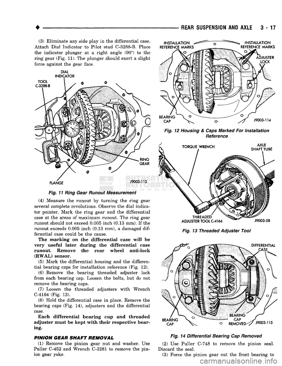
Attach Dial Indicator to Pilot stud C-3288-B. Place
the indicator plunger at a right angle (90°) to the ring gear (Fig. 11). The plunger should exert a slight
force against the gear face.
DIAL
INDICATOR
Fig.
11
Ring
Gear
Runout
Measurement
(4) Measure the runout by turning the ring gear
several complete revolutions. Observe the dial indica
tor pointer. Mark the ring gear and the differential
case at the areas of maximum runout. The ring gear
runout should not exceed 0.005 inch (0.13 mm). If the
runout exceeds 0.005 inch (0.13 mm), a damaged
dif
ferential case could be the cause.
The marking on the differential case will be
very useful later during the differential case
runout. Remove the rear wheel anti-lock (RWAL) sensor.
(5) Mark the differential housing and the differen
tial bearing caps for installation reference (Fig. 12).
(6) Remove the bearing threaded adjuster lock
from each bearing cap. Loosen the bolts, but do not
remove the bearing caps.
(7) Loosen the threaded adjusters with Wrench
C-4164 (Fig. 13).
(8) Hold the differential case in place. Remove the
bearing caps (Fig. 14), adjusters and the differential
case.
Each differential bearing cup and threaded
adjuster must be kept with their respective bear
ing.
PINION
GEAR
SHAFT
REMOVAL
(1) Remove the pinion gear nut and washer. Use
Puller C-452 and Wrench C-3281 to remove the pin
ion gear yoke.
Fig.
12
Housing
&
Caps
Marked For
Installation
Reference
Fig.
13 Threaded Adjuster Tool
Fig.
14
Differential
Bearing Cap
Removed
(2) Use Puller C-748 to remove the pinion seal.
Discard the seal. (3) Force the pinion gear out the front bearing to