1993 DODGE TRUCK wheel
[x] Cancel search: wheelPage 84 of 1502
•
FRONT SUSPENSION
AND
AXLE
2 - 31
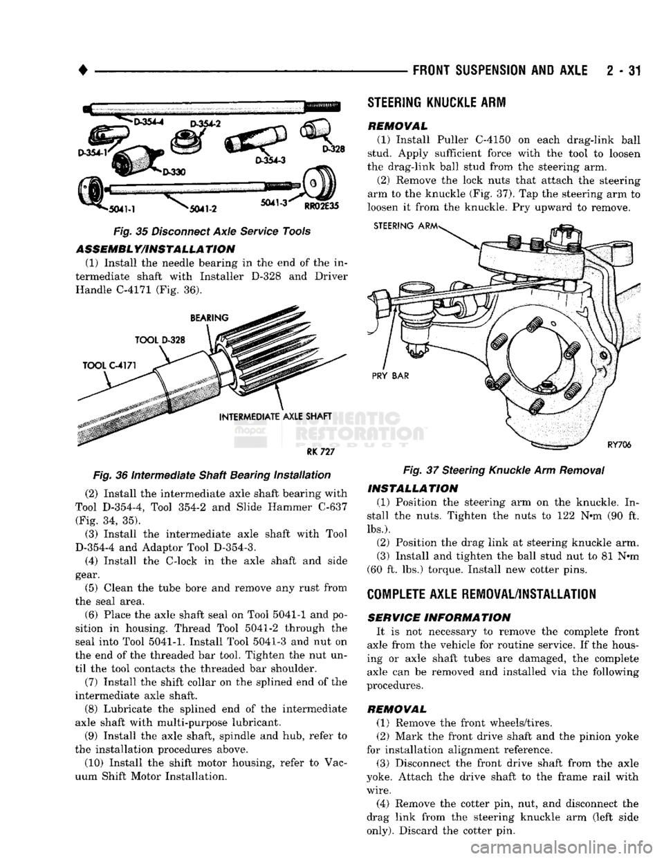
Fig. 35 Disconnect Axle Service Tools ASSEMBLY/INSTALLATION
(1) Install the needle bearing in the end of the in
termediate shaft with Installer D-328 and Driver Handle C-4171 (Fig. 36).
RK
727
Fig. 36 Intermediate Shaft Bearing installation (2) Install the intermediate axle shaft bearing with
Tool D-354-4, Tool 354-2 and Slide Hammer C-637 (Fig. 34, 35).
(3) Install the intermediate axle shaft with Tool
D-354-4 and Adaptor Tool D-354-3.
(4) Install the C-lock in the axle shaft and side
gear.
(5) Clean the tube bore and remove any rust from
the seal area.
(6) Place the axle shaft seal on Tool 5041-1 and po
sition in housing. Thread Tool 5041-2 through the
seal into Tool
5041-1.
Install Tool 5041-3 and nut on
the end of the threaded bar tool. Tighten the nut un
til the tool contacts the threaded bar shoulder.
(7) Install the shift collar on the splined end of the
intermediate axle shaft.
(8) Lubricate the splined end of the intermediate
axle shaft with multi-purpose lubricant.
(9) Install the axle shaft, spindle and hub, refer to
the installation procedures above. (10) Install the shift motor housing, refer to Vac
uum Shift Motor Installation.
STEERING
KNUCKLE
ARM
REMOVAL
(1) Install Puller C-4150 on each drag-link ball
stud. Apply sufficient force with the tool to loosen
the drag-link ball stud from the steering arm.
(2) Remove the lock nuts that attach the steering
arm to the knuckle (Fig. 37). Tap the steering arm to
loosen it from the knuckle. Pry upward to remove. Fig. 37 Steering Knuckle Arm Removal
INSTALLATION
(1) Position the steering arm on the knuckle. In
stall the nuts. Tighten the nuts to 122 N«m (90 ft.
lbs.).
(2) Position the drag link at steering knuckle arm.
(3) Install and tighten the ball stud nut to 81 N*m
(60 ft. lbs.) torque. Install new cotter pins.
COMPLETE
AXLE REMOVAL/INSTALLATION
SERVICE
INFORMATION
It is not necessary to remove the complete front
axle from the vehicle for routine service. If the hous
ing or axle shaft tubes are damaged, the complete axle can be removed and installed via the following
procedures.
REMOVAL (1) Remove the front wheels/tires.
(2) Mark the front drive shaft and the pinion yoke
for installation alignment reference.
(3) Disconnect the front drive shaft from the axle
yoke. Attach the drive shaft to the frame rail with
wire.
(4) Remove the cotter pin, nut, and disconnect the
drag link from the steering knuckle arm (left side
only).
Discard the cotter pin.
Page 105 of 1502
2
- 52
FRONT
SUSPENSION
AND
AXLE
•
PINION
SEAL
J9203-55
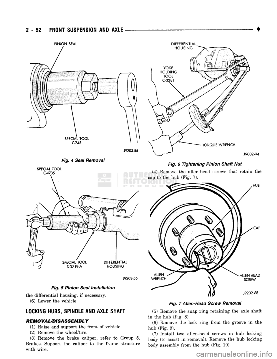
Fig. 4 Seal Removal
SPECIAL TOOL
G4735
J9203-56
Fig. 5 Pinion Seal Installation the differential housing, if necessary.
(6)
Lower the vehicle.
LOCKING HUBS, SPINDLE AND AXLE SHAFT
REM0VAL/D1SASSEMBL
Y
(1) Raise and support the front of vehicle. (2) Remove the wheel/tire.
(3) Remove the brake caliper, refer to Group 5,
Brakes. Support the caliper to the frame structure
with wire. DIFFERENTIAL
Fig. 6 Tightening Pinion Shaft Nut
(4) Remove the allen-head screws that retain the
cap to the hub (Fig. 7).
Fig. 7 Allen-Head Screw Removal (5) Remove the snap ring retaining the axle shaft
in the hub (Fig. 8).
(6)
Remove the lock ring from the groove in the
hub (Fig. 9).
(7) Install two allen-head screws in hub locking
body (to assist in removal). Remove the hub locking
body assembly from the hub (Fig. 10).
Page 106 of 1502
• ___— . ^
FRONT
SUSPENSION
AND
AXLE
2 - 53
SCREWDRIVER
J9202-70
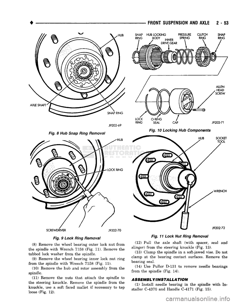
Fig.
9
Lock
Ring
Removal
(8) Remove the wheel bearing outer lock nut from
the spindle with Wrench 7158 (Fig. 11). Remove the
tabbed lock washer from the spindle.
(9) Remove the wheel bearing inner lock nut ring
from the spindle with Wrench 7158 (Fig. 11).
(10) Remove the hub and rotor assembly from the
spindle.
(11) Remove the nuts that attach the spindle to
the steering knuckle. Remove the spindle from the knuckle, use a soft faced mallet if necessary to tap
loose (Fig. 12).
SNAP
HUB
LOCKING
PRESSURE
CLUTCH
SNAP
RING
SEAL
CAP
J9202-71
Fig.
10
Locking
Hub
Components
Fig.
11
Lock
Nut
Ring
Removal
(12) Pull the axle shaft (with spacer, seal and
slinger) from the steering knuckle (Fig. 13).
(13) Clamp the spindle in a soft-jawed vise. Do not
clamp at the bearing contact surfaces. Remove the
bearing seal.
(14) Use Puller D-131 to remove needle bearings
from the spindle (Fig. 14).
ASSEMBL
Y/INSTALLA
TION
(1) Install needle bearing in the spindle with In
staller C-4370 and Handle C-4171 (Fig. 15).
Page 107 of 1502
2
- 54
FRONT SUSPENSION
AND
AXLE
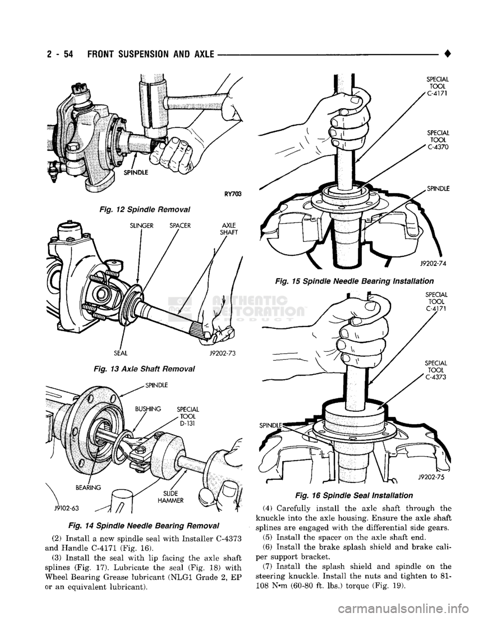
Fig.
12 Spindle Removal
SEAL
J9202-73
Fig.
13 Axle Shaft Removal
Fig.
14
Spindle
Needle Bearing
Removal
(2) Install a new spindle seal with Installer C-4373
and Handle C-4171 (Fig. 16).
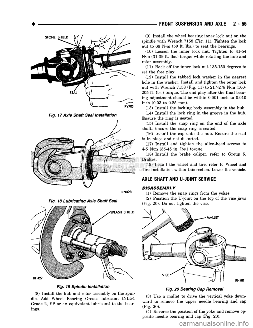
(3) Install the seal with lip facing the axle shaft
splines (Fig. 17). Lubricate the seal (Fig. 18) with
Wheel Bearing Grease lubricant (NLGI Grade 2, EP
or an equivalent lubricant). •
Fig.
15
Spindle
Needle Bearing
Installation
Fig.
16
Spindle
Seal
Installation
(4) Carefully install the axle shaft through the
knuckle into the axle housing. Ensure the axle shaft splines are engaged with the differential side gears.
(5) Install the spacer on the axle shaft end.
(6) Install the brake splash shield and brake cali
per support bracket.
(7) Install the splash shield and spindle on the
steering knuckle. Install the nuts and tighten to 81- 108 N-m (60-80 ft. lbs.) torque (Fig. 19).
Page 108 of 1502
•
Fig.
17 Axle Shaft
Seal
Installation
Fig.
19
Spindle
Installation
(8) Install the hub and rotor assembly on the spin
dle.
Add Wheel Bearing Grease lubricant (NLGI Grade 2, EP or an equivalent lubricant) to the bear
ings.
FRONT
SUSPENSION
AND
AXLE
2 - 51
Fig.
20 Bearing Cap
Removal
(3) Use a mallet to drive the vertical yoke down
ward to remove the upper needle bearing and cap (Fig. 20).
(4) Reverse the position of the yoke and remove op
posite needle bearing and cap (Fig. 20). (9) Install the wheel bearing inner lock nut on the
spindle with Wrench 7158 (Fig. 11). Tighten the lock
nut to 68 N*m (50 ft. lbs.) to seat the bearings. (10) Loosen the inner lock nut. Tighten to 41-54
N*m (31-39 ft. lbs.) torque while rotating the hub and
rotor assembly.
(11) Back off the inner lock nut 135-150 degrees to
set the free play.
(12) Install the tabbed lock washer in the nearest
hole in the washer. Install and tighten the outer lock nut with Wrench 7158 (Fig. 11) to 217-278 N-m (160-205 ft. lbs.) torque. The end play after the final bear
ing adjustment should be within 0.001 inch to 0.010 inch (0.03 to 0.25 mm).
(13) Install the locking body assembly in the hub.
(14) Install the lock ring in the groove in the hub.
Ensure the ring is seated. (15) Install the snap ring on the end of the axle
shaft. Ensure the snap ring is seated.
(16) Install the cap onto the hub. Ensure the seal
is in place and not distorted.
(17) Install and tighten the allen-head screws to
4-5 N-m (35-45 in. lbs.) torque.
(18) Install the brake caliper, refer to Group 5,
Brakes. (19) Install the wheel and tire, refer to Wheel and
Tire Installation within this section. Lower the vehicle.
AXLE SHAFT AND
U-JOINT
SERVICE DISASSEMBLY
(1) Remove the snap rings from the yokes.
(2) Position the U-joint on the top of the vise jaws
(Fig. 20). Do not tighten the vise.
Page 112 of 1502
•
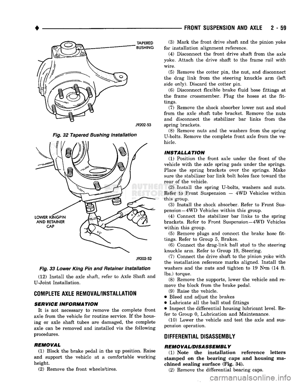
TAPERED
BUSHING
J9202-53
Fig.
32 Tapered
Bushing
Installation
J9202-52
Fig.
33
Lower
King
Pin and Retainer
Installation
(12) Install the axle shaft, refer to Axle Shaft and
U-Joint Installation.
COMPLETE
AXLE REMOVAL/INSTALLATION SERVICE
INFORMATION
It is not necessary to remove the complete front
axle from the vehicle for routine service. If the hous
ing or axle shaft tubes are damaged, the complete axle can be removed and installed via the following
procedures.
REMOVAL
(1) Block the brake pedal in the up position. Raise
and support the vehicle at a comfortable working
height.
(2) Remove the front wheels/tires.
FRONT SUSPENSION
AND
AXLE
2 - 59
(3) Mark the front drive shaft and the pinion yoke
for installation alignment reference.
(4) Disconnect the front drive shaft from the axle
yoke. Attach the drive shaft to the frame rail with
wire.
(5) Remove the cotter pin, the nut, and disconnect
the drag link from the steering knuckle arm (left side only). Discard the cotter pin.
(6) Disconnect flexible brake fluid hose fittings at
the frame crossmember. Plug the hoses at the fit
tings.
(7) Remove the shock absorber lower nut and stud
from the axle shaft tube bracket. Remove the nuts and disconnect the stabilizer bar links from the
spring brackets. (8) Remove nuts and the washers from the spring
U-bolts. Remove the complete front axle from the ve
hicle.
INSTALLATION (1) Position the front axle under the front of the
vehicle with the axle spring pads under the springs.
Place the spring brackets over the springs. Make sure the stabilizer bar link bolt holes face toward the
rear of the vehicle.
(2) Install the spring U-bolts, washers and nuts.
Refer to Front Suspension — 4WD Vehicles within
this group. (3) Install the shock absorber. Refer to Front Sus
pension—4 WD Vehicles within this group.
(4) Connect the stabilizer bar links to the spring
brackets. Refer to Front Suspension—4WD Vehicles within this group.
(5) Remove plugs and connect the brake hose fit
tings.
Refer to Group 5, Brakes. (6) Connect the drag-link ball stud to the steering
knuckle arm. Refer to Group 19, Steering. (7) Connect the drive shaft to the pinion yoke with
the installation reference marks aligned. Install the
washers and the nuts and tighten to 19 N-m (14 ft. lbs.) torque.
(8) Remove the supports, lower the vehicle and re
move the block from the brake pedal.
(9) Raise the vehicle.
• Bleed and adjust the brakes
• Lubricate all the ball stud fittings
• Inspect the differential housing lubricant level. Re
fer to Group 0, Lubrication and Maintenance.
(10) Lower the vehicle and test the axle and sus
pension operation.
DIFFERENTIAL DISASSEMBLY
REMOVAL/DISASSEMBLY
(1) Note the installation reference letters
stamped on the bearing caps and housing ma
chined sealing surface (Fig. 34).
(2) Remove the differential bearing caps.
Page 128 of 1502
FRONT
SUSPENSION
AND
AXLE
2 - 75
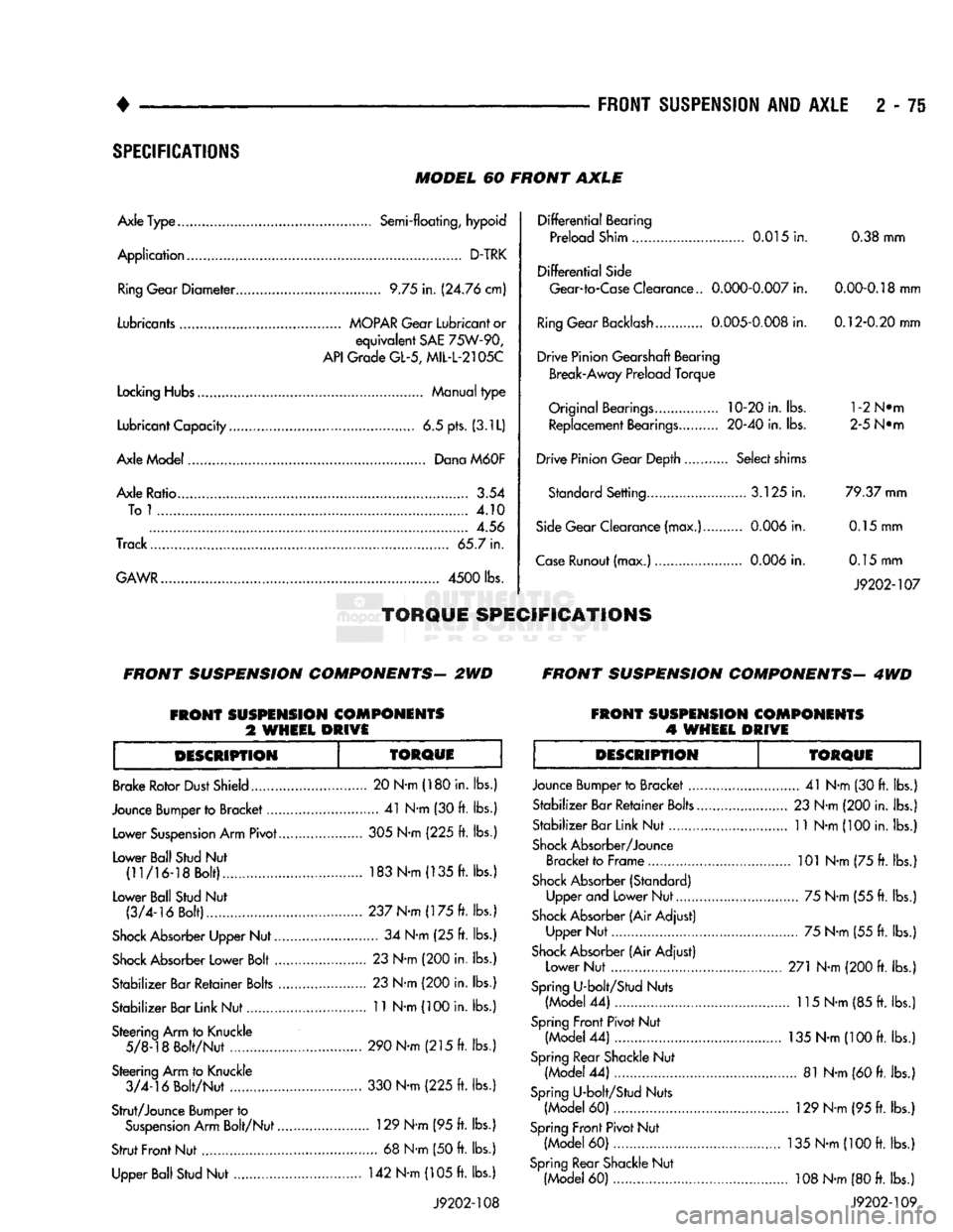
SPECIFICATIONS
MODEL
60
FRONT
AXLE
Axle Type........
Semi-floating,
hypoid
Application
D-TRK Ring Gear
Diameter
9.75
in.
(24.76 cm)
Lubricants
MOPAR
Gear
Lubricant
or
equivalent
SAE
75W-90,
API
Grade
GL-5,
MIL-L-2105C
Locking
Hubs Manual
type
Lubricant Capacity
6.5
pts. (3.1L)
Axle Model Dana
M60F
Axle Ratio.........
3.54
Tol
4.10
4.56
Track... 65.7
in.
GAWR....................
4500
lbs.
TORQUE
SPECIFICATIONS
Differential
Bearing
Preload Shim 0.015
in.
0.38
mm
Differential
Side Gear-to-Case Clearance..
0.000-0.007
in.
0.00-0.18
mm
Ring
Gear Backlash 0.005-0,008
in.
0.12-0.20 mm
Drive Pinion Gearshaft Bearing Break-Away Preload Torque
Original
Bearings....
10-20
in. lbs. l-2N®m Replacement Bearings. 20-40
in.
lbs. 2-5 N®m
Drive Pinion Gear Depth Select shims Standard Setting.... 3.125
in.
79.37 mm
Side
Gear Clearance (max.) 0.006
in.
0.15
mm
Case
Runout (max.) 0.006
in.
0.15
mm
J9202-107
FRONT
SUSPENSION
COMPONENTS-
2WD
FRONT
SUSPENSION
COMPONENTS-
4WD
FRONT
SUSPENSION
COMPONENTS
%
WHEEL
DRIVE
FRONT
SUSPENSION
COMPONENTS
4
WHEEL
DRIVE
DESCRIPTION
TOROUE
Brake Rotor
Dust
Shield
Jounce Bumper to Bracket.... Lower
Suspension
Arm Pivot.
Lower Ball Stud
Nut
(11/16-18 Bolt)...............
Lower Ball Stud
Nut
(3/4-16 Bolt).....
Shock
Absorber Upper Nut..
Shock
Absorber Lower Bolt
..
Stabilizer Bar Retainer
Bolts
.
Stabilizer Bar Link Nut
Steering Arm to Knuckle 5/8-18 Bolt/Nut
.............
Steering Arm to Knuckle 3/4-16 Bolt/Nut . 20 N-m (180 in.
lbs.
....
41
N-m
(30
ft. lbs.
305
N-m (225
ft. lbs.
183
N-m (135
ft. lbs.
237 N-m (175
ft. lbs.
....
34
N-m
(25 ft.
lbs. .
23
N-m
(200
in. lbs.
.
23
N-m
(200
in. lbs.
. 11 N-m
(100
in. lbs.
Strut/Jounce Bumper to
Suspension
Arm Bolt/Nut.
Strut
Front
Nut Upper Ball Stud
Nut
290 N-m (215
ft. lbs.
330 N-m (225
ft.
lbs.
.. 129 N-m (95
ft.
lbs.
....
68
N-m
(50
ft.
lbs.
142
N-m
(105
ft.
lbs.
J9202-108
DESCRIPTION
TORQUE
Jounce Bumper to Bracket
....
Stabilizer Bar Retainer
Bolts..
Stabilizer Bar Link Nut
Shock
Absorber/Jounce Bracket to Frame
Shock
Absorber (Standard) Upper and Lower Nut
Shock
Absorber (Air Adjust) Upper Nut
Shock
Absorber (Air Adjust) Lower Nut
Spring
U-bolt/Stud Nuts (Model
44) ...
Spring
Front Pivot Nut (Model
44)
Spring
Rear Shackle
Nut
(Model
44)
Spring
U-bolt/Stud Nuts (Model
60)
Spring
Front
Pivot Nut (Model
60)
Spring
Rear Shackle Nut (Model
60)
...
41
N-m (30
ft.
lbs.)
23
N-m (200 in.
lbs.)
11
N-m
(100
in.
lbs.)
.. 101 N-m (75
ft.
lbs.)
.... 75 N-m (55
ft.
lbs.)
.... 75 N-m (55
ft.
lbs.)
271 N-m
(200
ft.
lbs.)
.. 115 N-m (85
ft.
lbs.)
135
N-m (100
ft.
lbs.)
.... 81 N-m
(60
ft.
lbs.)
..
129
N-m
(95
ft.
lbs.)
135
N-m (100
ft.
lbs.)
,.
108
N-m
(80
ft.
lbs.)
J9202-109
Page 129 of 1502
2
- 76
FRONT
SUSPENSION
AND
AXLE
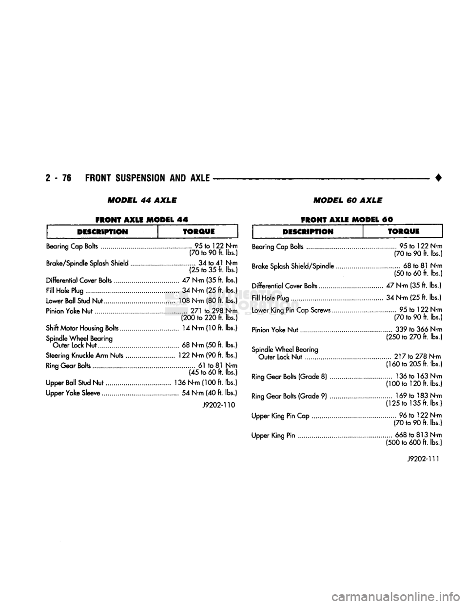
MODEL
44 AXLE
MODEL
60 AXLE
FRONT
AXLE MODEL 44
FRONT
AXLE MODEL #0
DESCRIPTION
TORQUE
Bearing Cap
Bolts
95 to 122 N-m (70 to 90 ft. lbs.)
Brake/Spindle
Splash
Shield 34 to 41 N-m
(25 to 35 ft. lbs.)
Differential
Cover
Bolts
47 N-m (35 ft. lbs.)
Fill
Hole Plug 34 N-m (25 ft. lbs.)
Lower Ball Stud Nut 108 N-m (80 ft. lbs.)
Pinion Yoke Nut 271 to 298 N-m (200 to 220 ft. lbs.)
Shift Motor
Housing
Bolts 14 N-m (10 ft. lbs.) Spindle
Wheel
Bearing
Outer
Lock Nut...... 68 N-m (50 ft. lbs.)
Steering Knuckle Arm Nuts 122 N-m (90 ft. lbs.)
Ring
Gear
Bolts
61 to 81 N-m (45 to 60 ft. lbs.)
Upper Ball Stud Nut 136 N-m (100 ft. lbs.)
Upper Yoke Sleeve 54 N-m (40 ft. lbs.)
J9202-110
DESCRIPTION
TORQUE
Bearing Cap Bolts
Brake
Splash
Shield/Spindle.
Differential
Cover Bolts
Fill
Hole Plug
Lower King Pin Cap Screws...
Pinion Yoke Nut.
Spindle
Wheel
Bearing
Outer
Lock Nut
Ring
Gear
Bolts
(Grade 8)
Ring
Gear
Bolts
(Grade 9)
Upper King Pin Cap
Upper King Pin 95 to 122 N-m
(70 to 90 ft. lbs.)
68 to 81 N-m
(50 to 60 ft. lbs.)
47 N-m (35 ft. lbs.) 34 N-m (25 ft. lbs.) 95 to 122 N-m
(70 to 90 ft. lbs.) 339 to 366 N-m
(250 to 270 ft. lbs.)
.... 217 to 278 N-m (160 to 205 ft. lbs.)
136tol63N-m
(100 to 120 ft. lbs.)
..... 169 to 183 N-m (125 to 135 ft. lbs.)
96 to 122 N-m
(70 to 90 ft. lbs.)
668 to 813 N-m
(500 to 600 ft. lbs.)
J9202-111