1993 DODGE TRUCK wheel
[x] Cancel search: wheelPage 56 of 1502
FRONT SUSPENSION
AND
AXLE
2 - 3
FRONT
WHEEL
ALIGNMENT
GENERAL
INFORMATION
Front wheel alignment involves
the
correct posi
tioning
of the
tire contact patch
in
relation
to the
pavement.
The
positioning
is
accomplished through
the suspension
and
steering linkage adjustments.
An
alignment
is
essential
for
efficient steering
and
direc
tional stability.
The
most important factors
of
front
end alignment
are
camber, caster
and toe
position. Routine inspection
of
the front
suspension
and
steering components
is a
good
preventative
maintenance practice.
Inspection
also
helps
to
ensure
safe operation
of the
vehicle.
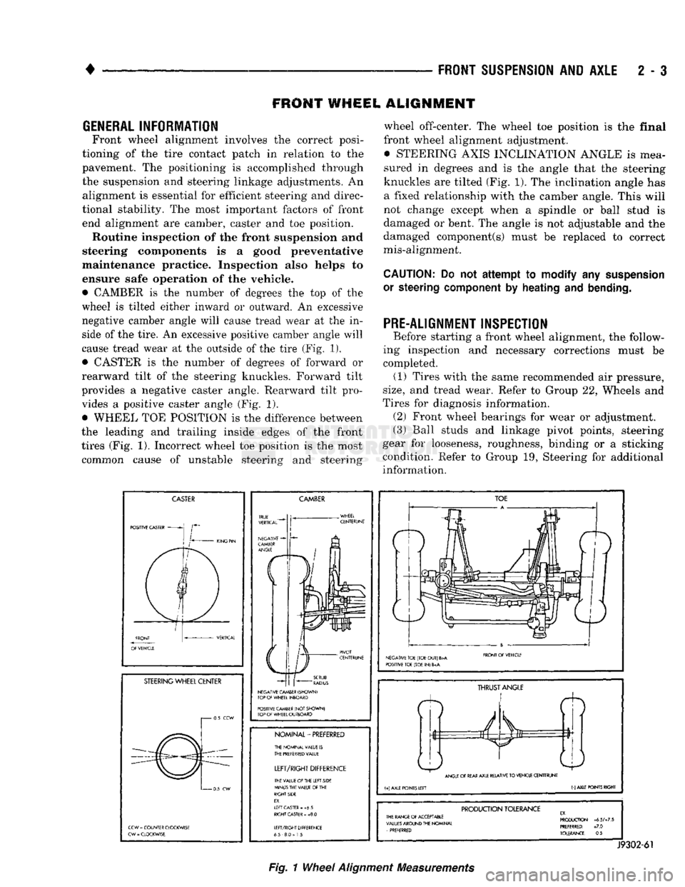
• CAMBER
is the
number
of
degrees
the top of the
wheel
is
tilted either inward
or
outward.
An
excessive
negative camber angle will cause tread wear
at the in
side
of
the tire.
An
excessive positive camber angle will
cause tread wear
at the
outside
of
the tire (Fig.
1),
• CASTER
is the
number
of
degrees
of
forward
or
rearward tilt
of the
steering knuckles. Forward tilt
provides
a
negative caster angle. Rearward tilt pro vides
a
positive caster angle
(Fig. 1).
• WHEEL
TOE
POSITION
is the
difference between
the leading
and
trailing inside edges
of the
front
tires (Fig.
1).
Incorrect wheel
toe
position
is the
most common cause
of
unstable steering
and
steering wheel off-center.
The
wheel
toe
position
is the
final
front wheel alignment adjustment. • STEERING AXIS INCLINATION ANGLE
is
mea
sured
in
degrees
and is the
angle that
the
steering
knuckles
are
tilted (Fig. 1).
The
inclination angle
has
a fixed relationship with
the
camber angle. This will
not change except when
a
spindle
or
ball stud
is
damaged
or
bent.
The
angle
is not
adjustable
and the
damaged component(s) must
be
replaced
to
correct
mis-alignment.
CAUTION:
Do not
attempt to modify
any
suspension
or steering
component
by
heating
and
bending.
PRE-ALIGNMENT INSPECTION
Before starting
a
front wheel alignment,
the
follow
ing inspection
and
necessary corrections must
be
completed.
(1)
Tires with
the
same recommended
air
pressure,
size,
and
tread wear. Refer
to
Group
22,
Wheels
and
Tires
for
diagnosis information. (2) Front wheel bearings
for
wear
or
adjustment.
(3) Ball studs
and
linkage pivot points, steering
gear
for
looseness, roughness, binding
or a
sticking
condition. Refer
to
Group
19,
Steering
for
additional information.
CASTER
POSITIVE CASTER
STEERING
WHEEL CENTER
i 0.5
CCW
0
5
CW
CCW
=
COUNTER CLOCKWISE
CW
-
CLOCKWISE
CAMBER
NEGATIVE CAMBER (SHOWN)
TOP
OF
WHEEL INBOARD
POSITIVE CAMBER
(NOT
SHOWN)
TOP
OF
WHEEL OUTBOARD
NOMINAL-PREFERRED
THE NOMINAL VALUE
IS
THE
PREFERRED
VALUE
LEFT/RIGHT
DIFFERENCE
THE VALUE
Of
THE LEFT SIDE
MINUS THE VALUE
OF
THE
RIGHT SIDE
EX.
If
FT CASTER
- +6 5
RIGHT
CASTER
»
+8.0
LEFT/RIGHT DIFFERENCE
65 8.0
=
1
5
TOE
NEGATIVE TOE (TOE
OUT)
B>A
POSITIVE TOE (TOE
IN) 6
FRONT
Of
VEHICLE
ft
THRUST
ANGLE
ANGLE
OF
REAR
AXLE RELATIVE
TO
VEHICLE CENTERUNE
(+)
AXLE POINTS LEFT
(-)
AXLE POINTS RIGHT
PRODUCTION
TOLERANCE
THE RANGE
Of
ACCEPTABLE
VALUES
AROUND THE NOMINAL
-
PREFERRED PRODUCTION
+6.5A7.5
PREFERRED:
+7.0
TOLERANCE:
0.5
J9302-61
Fig.
1
Wheel
Alignment
Measurements
Page 57 of 1502
2 - 4 FRONT SUSPENSION AND AXLE
•
I
FRONT END
|
|*?£E;
LOOSE
OR WORN
FRONT WHEEL
BEARINGS
LOOSE
C
SHOCKS
MOUNTir
WAR
SHOCK
A )RWORN
JSORBER
nIG
HARD-
E
OR
BSORBER
EXCiSSIVE
PLAY
STEERING
LINKAGE
LOOSE
OR WORN
FRONT WHEEL
BEARINGS
LOOSE
C
STEERINC
SHAFT
C
)RWORN
7
COLUMN
OUPLING
DIFFICULT
STEERING
LOOSE
OR WORN
WHEEL BEARINGS
TIRE/V
OUT OF
f
VHEEL
JA
LANCE
LOW OR UNEVEN
TIRE
AIR
PRESSURE
LO(
WHEEL B
DSE
EARINGS
LOW OR UNEVEN
TIRE AIR
PRESSURE
1vsnciEi
I
1
PULLS
TO I
I
|
ONE SIDE
j
LOOSE,
WORN
OR
GLAZED
P/S PUMP BELT LOW OR UNEVEN
TIRE PRESSURE
WHILE BR
REFE
BRAKES
AKING—
R
TO
SERVICE
LOOSE
STEERING
GEAR-TO-FRAME
RAIL BOLTS
LOOSE
STEERING
GEAR-TO-FRAME
RAIL BOLTS UNEVEN TIRE TREAD
WEAR,
OR
EX
CESSIVELY
WORN TIRE TREAD
BROKEN
OR WEAK
REAR
SPRING LOW
POWER STEERING
FLUID
LEVEL
BROKEN
OR WEAK
REAR
SPRING
WORN
UPPER
SUSPENSION ARM BUSHINGS WORN TIE-
ROD
END
BALL
STUDS WORN TIE-
ROD
END
BALL
STUDS
SHOCK
ABSORBER
NOT FUNCTIONING
CORRECTLY
LACK
OF ASSIST
FROM POWER
STEERING
PUMP
LOOSE
OR WORN
SUSPENSION
BUSHINGS
WORN LOWER
SUSPENSION
ARM
PIVOT
BUSHINGS INCORRECT
STEERING
GEAR ADJUSTMENT
LOOSE
OR WORN
SUSPENSION
ARM
BUSHINGS
INCORRECT
STEERING
GEAR ADJUSTMENT
BALL
STUDS
REQUIRE
LUBRICATION INCORRECT FRONT
WHEEL ALIGNMENT (EITHER CASTER OR CAMBER)
LOOSE
LOWER
SUSPENSION
ARM
LOOSE
OR WORN
UPPER
SUSPENSION ARM BALL STUDS
LOOSE
OR WORN
SUSPENSION
ARM
BUSHINGS
STEERING
GEAR
LUBRICANT LEVEL LOW
WORN ISOLATOR
PAD
BETWEEN COIL
SPRING
AND
FRAME
BRACKET INCORRECT FRONT-
WHEEL ALIGNMENT (PARTICULARLY
CASTER)
INCORRECT FRONT
WHEEL ALIGNMENT INCORRECT
STEERING
GEAR ADJUSTMENT
STEERING
GEAR
MALFUNCTION
INCORRECT FRONT
WHEEL ALIGNMENT (PARTICULARLY
CASTER)
J9002-97
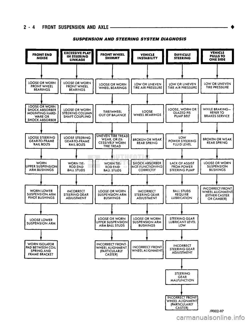
SUSPENSION AND STEERING
SYSTEM
DIAGNOSIS
Page 58 of 1502

•
FRONT
SUSPENSION
AND
AXLE
2 - 5 (4) Front wheels for excessive radial, lateral
runout and unbalance. Refer to Group 22, Wheels and Tires for diagnosis information.
(5) Suspension components for wear and noise. Check
components for correct torque. Refer to Groups 2 and 3, Suspension and Axle for additional information.
WHEEL
ALIGNMENT
MEASUREMENTS/ADJUSTMENTS
The front wheel alignment positions must be set to
the specified limits. This will prevent abnormal tire
tread wear. The equipment manufacturer's recommenda
tions for use of their
equipment
should always
be followed. All
damaged
front suspension sys
tem components
should
be replaced. Do not at tempt to straighten any
bent
component.
CAMBER AND CASTER-2WD VEHICLES Camber and caster angle adjustments involve repo
sitioning the upper suspension arm cam adjustment
bolts (Fig. 2). Alignment adjustments are accom
plished by loosening the nuts and changing the posi
tion of the cam bolt.
(1) Remove all foreign material from the adjust
ment bolt threads.
(2) Record the camber and caster measurements
before loosening the adjustment bolt nuts.
(3) The camber angle should be adjusted as near as
possible to the preferred angle. The caster should be
the same at both sides of the vehicle. Refer to the Specifications chart.
CAMBER AND CASTER—4WD VEHICLES For 4WD vehicles, the correct wheel camber (verti
cal tilt) angle is factory preset at zero degree (0°).
Camber cannot be altered by adjustment.
CAUTION: Do not attempt to
adjust
the
camber
an
gle by
heating
or bending the axle or any
suspen
sion
component. If camber angle is
incorrect,
the
component(s)
causing
an
incorrect
angle must be replaced.
(1) It is important that the camber (vertical tilt)
angle be the same for both front wheels.
(2) The camber angle should be measured with ac
curate wheel alignment equipment. The acceptable
range is -1° to +1°. Refer to the Specifications chart.
Road test the vehicle and observe the steering
wheel return-to-center position. Before road testing,
check
and
correct
the tire
inflation pressures. Inflate
both
of the front tires
with exactly the
same
pressure.
During the road test, make vehicle turns to both
the left and right. If the steering wheel returns to
ward the center position unassisted, the caster angle is correct. However, if the steering wheel does not re turn toward the center position unassisted, an incor
rect caster angle is probable.
(1) The caster angle is factory preset at positive
two degrees
(
+
2°).
The acceptable range is +1/2° to +
3
1/2°.
(2) The caster angle should be measured with ac
curate wheel alignment equipment.
(3) Caster angle can be adjusted by installing ta
pered shims between the front axle pads and the spring brackets. The caster angle should be adjusted
as near as possible to the preferred angle.
(4) Record the caster measurement before remov
ing the original shims from the spring pads.
(5) The caster should be the same at both sides of
the vehicle. Refer to the Specifications chart.
RN1030
Fig.
2 Caster &
Camber
Adjustment Location—2WD
Vehicles
WHEEL TOE POSITION The wheel toe position adjustment should be the fi
nal front wheel alignment adjustment. In all in stances, follow the equipment manufacturer's
recommended procedure.
(1) Secure the steering wheel with the front wheels
in the straight-ahead position. For vehicles equipped
with power steering, start the engine before straight ening the wheels.
With power steering, the engine should be op
erating during the wheel toe position adjust
ment.
(2) Loosen the tie rod adjustment sleeve clamp
bolts (Fig. 3).
(3) Adjust the wheel toe position by rotating the
tie rod adjustment sleeve (Fig. 3). Rotate each tie-rod end in the direction of
sleeve rotation during the adjustment (Fig. 3).
This will ensure that both tie-rod ends are at the center of their travel.
(4) If applicable, turn the ignition switch off.
Page 60 of 1502
•
FRONT
SUSPENSION
AND
AXLE
2 • 7
FRONT SUSPENSION
—2WD
VEHICLES
INDEX
page
Coil Springs
9
Lower Ball Stud
. 10
Lower Suspension
Arm 10
Lower Suspension
Arm
Bushing
11
Lower Suspension
Arm
Strut
8
Service
Information
7
Shock
Absorber
9
page
Stabilizer
Bar 8
Steering Knuckle
13
Upper Ball Stud
11
Upper Suspension
Arm 11
Upper Suspension
Arm
Bushing Replacement
. . . 12
Wheel
Hub and
Bearings
7
SERVICE
INFORMATION
Periodic lubrication of the front suspension (steer
ing) system components is required. Refer to Group 0, Lubrication And Maintenance for the service in
terval.
Rubber bushings must never be lubricated.
All front suspension components that are
cushioned by rubber should be tightened with
the suspension system at the normal height.
WHEEL
HUB
AND
BEARINGS
REMOVAL (1) Block the brake pedal in the up (non-depressed)
position.
(2) Raise and support the vehicle.
(3) Remove the wheel.
(4) Remove bolts from the disc brake caliper.
(5) Separate the disc brake caliper from the rotor.
Position and support the caliper away from the im
mediate work area. Do not allow the caliper to
hang from the brake fluid hose.
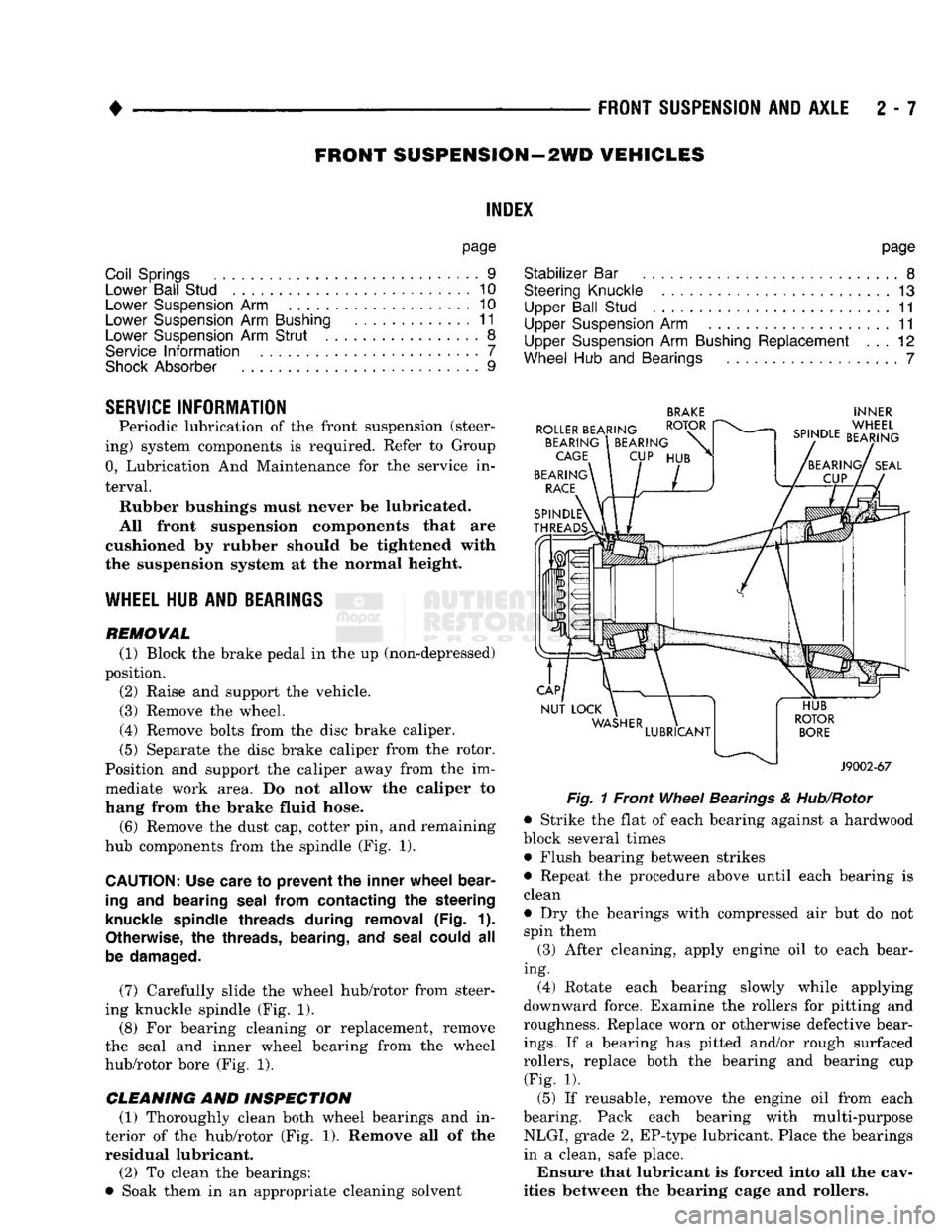
(6) Remove the dust cap, cotter pin, and remaining
hub components from the spindle (Fig. 1).
CAUTION:
Use care
to
prevent
the
inner wheel bear
ing
and
bearing seal from contacting
the
steering
knuckle spindle threads during removal
(Fig. 1).
Otherwise,
the
threads, bearing,
and
seal could
all
be damaged.
(7) Carefully slide the wheel hub/rotor from steer
ing knuckle spindle (Fig. 1).
(8) For bearing cleaning or replacement, remove
the seal and inner wheel bearing from the wheel
hub/rotor bore (Fig. 1).
CLEANING AND INSPECTION (1) Thoroughly clean both wheel bearings and in
terior of the hub/rotor (Fig. 1). Remove all of the residual lubricant.
(2) To clean the bearings:
• Soak them in an appropriate cleaning solvent
BRAKE
INNER
Fig.
1 Front
Wheel
Bearings
&
Hub/Rotor
• Strike the flat of each bearing against a hardwood
block several times • Flush bearing between strikes
• Repeat the procedure above until each bearing is
clean
• Dry the bearings with compressed air but do not spin them
(3) After cleaning, apply engine oil to each bear
ing. (4) Rotate each bearing slowly while applying
downward force. Examine the rollers for pitting and
roughness. Replace worn or otherwise defective bear
ings.
If a bearing has pitted and/or rough surfaced
rollers, replace both the bearing and bearing cup (Fig. 1).
(5) If reusable, remove the engine oil from each
bearing. Pack each bearing with multi-purpose NLGI, grade 2, EP-type lubricant. Place the bearings
in a clean, safe place.
Ensure that lubricant is forced into all the cav
ities between the bearing cage and rollers.
Page 61 of 1502
2
- 8
FRONT SUSPENSION
AND
AXLE
• INSTALLATION
(1) If a bearing and cup must be replaced, remove
the cup from the wheel hub/rotor bore (Fig. 1). Use a
brass drift or an appropriate removal tool to tap out
the cup.
(2) Install the replacement bearing cup(s) with an
appropriate installation tool. (3) Apply lubricant to surface area of the wheel
hub/rotor bore. Install the inner wheel bearing in the
hub/rotor. Install a replacement bearing seal with an appropriate seal installation tool. (4) Inspect the bearing and seal contact surfaces on
the steering knuckle spindle for burrs and/or rough ness (Fig. 1).
(5) Remove all the rough contact surfaces from the
spindle. Apply a coating of multi-purpose NLGI,
grade 2, EP-type lubricant to the spindle surface.
CAUTION: Us© care to prevent the inner
wheel
bear
ing
and bearing
seal
from contacting the steering
knuckle
spindle
threads during removal (Fig. 1).
Otherwise,
the threads, bearing, and
seal
could
be
damaged.
(6) Carefully slide the wheel hub/rotor onto the
spindle.
Install the outer wheel bearing, the washer and
nut.
(7) Tighten the nut to 41 to 54 Nnn (30 to 40 ft.
lbs.) torque while rotating the wheel hub/rotor. Stop
the hub/rotor and loosen the nut to completely re
lease the bearing preload torque. Next, tighten the
nut finger-tight, install the nut lock. Install a re
placement cotter pin.
(8) The wheel bearing adjustment (above) should
have 0.001 to 0.003 inch (0.254 to 0.0762 mm) end
play.
(9) Clean the dust cap. Apply a coating of multi
purpose NLGI, grade 2, EP-type lubricant to internal surface. Install the cap. Do not fill the dust cap with lubricant. (10) Install the brake caliper, refer to Group 5,
Brakes. (11) Install the wheel and tire, refer to Wheel and
Tire Installation in this section. Lower the vehicle.
LOWER SUSPENSION ARM STRUT
REMOVAL (1) Raise and support the vehicle.
(2) Use a small drift and a hammer to drive the
spring pin from the front of the strut. Remove the
spring pin, nut, retainer and bushing from the end of
the strut (Fig. 2).
(3) Remove the strut rear bolts and jounce bumper
from the bracket. Remove the strut from the vehicle (Fig. 2).
NUT
FRONT
RETAINER
STRUT
J9002-120
Fig. 2 Lower Suspension Arm Strut Removal/ Installation INSTALLATION
(1) Position the rear retainer and rear bushing on
the front end of the strut (Fig. 2).
(2) Carefully slide the strut into position. Install
the rear bolts. Tighten the bolts to 182 Nnn (135 ft. lbs.) torque.
(3) Install the front bushing, front retainer and
nut at the front end of the strut. Tighten the nut
with 70 Nnn (52 ft. lbs.) torque.
(4) Install the spring pin.
STABILIZER
BAR
REMOVAL
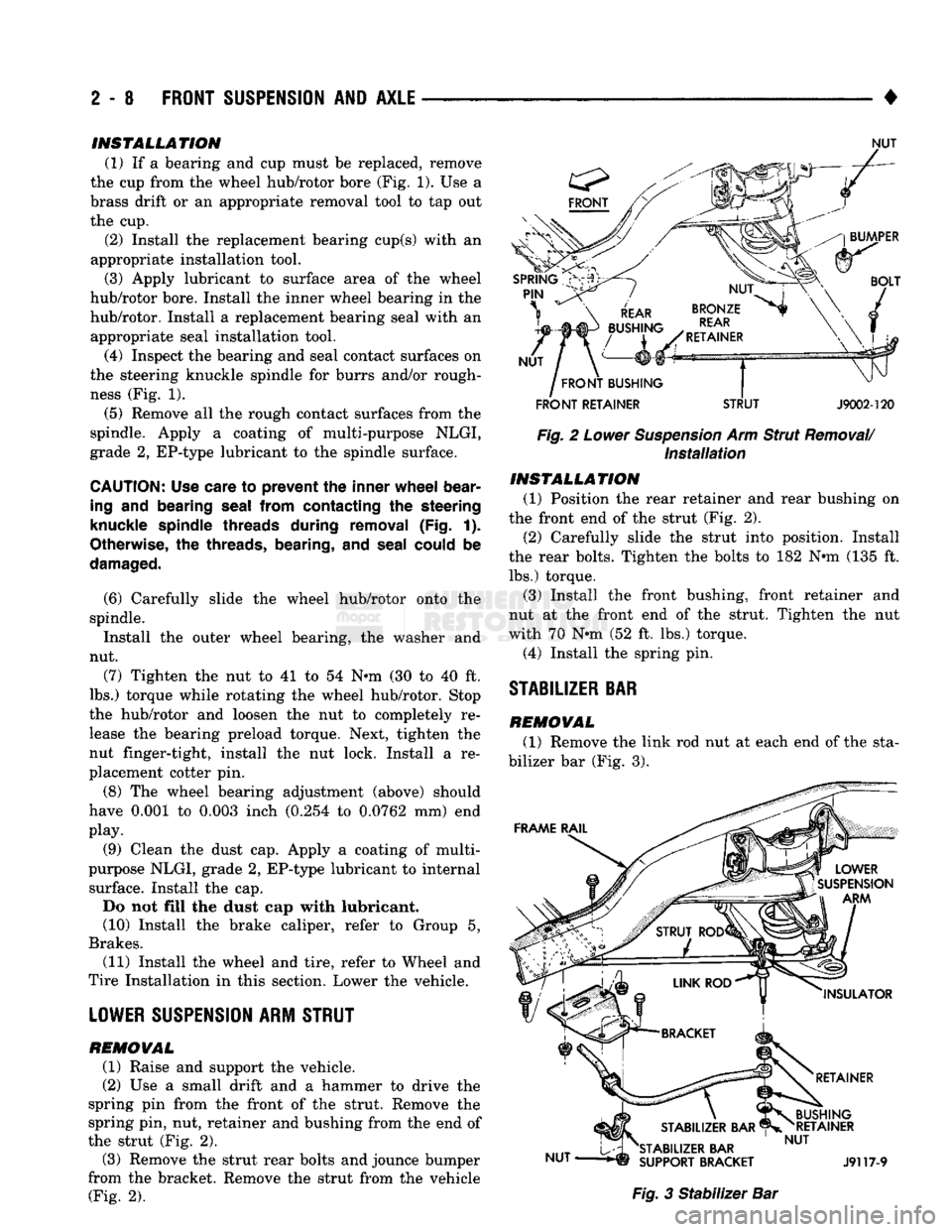
(1) Remove the link rod nut at each end of the sta
bilizer bar (Fig. 3). Fig. 3 Stabilizer Bar
Page 63 of 1502
2
- 10
FRONT SUSPENSION
AND
AXLE
• INSTALLATION
(1) Position the spring and isolation pad on the
suspension arm. Install the spring compressor tool.
Compress the spring until the lower suspension arm
can be properly positioned in the steering knuckle.
(2) Install the nuts on the ball studs. Tighten the
upper nut to 142 Nnn (105 ft. lbs.) torque. Tighten
the lower nut.
* 11/16-16 bolt, to 183 Nnn (135 ft. lbs.) torque
• 3/4-16 bolt, to 237 Nnn (175 ft. lbs.) torque Install replacement cotter pins.
(3) Install the strut.
(4) Connect the stabilizer bar.
(5) Install the shock absorber.
(6) Install the brake splash shield on the steering
knuckle. Tighten the screws to 23 Nnn (200 in. lbs.)
torque.
(7) Carefully install the hub/rotor and bearings.
(8) Install the brake caliper, refer to Group 5, Brakes.
(9) Install the wheel and tire, refer to Wheel and Tire
Installation within this section. Lower the vehicle. (10) Test the vehicle brakes and the suspension for
proper operation.
LOWER SUSPENSION
ARM
REMOVAL
(1) Follow procedure under Coil Spring Removal.
(2) Remove hex-head mounting bolt from the cross-
member. (3) Remove the lower suspension arm from vehicle.
INSTALLATION (1) Position lower suspension arm on vehicle.
(2) Install mounting bolt, tighten finger-tight.
(3) Follow procedure under Coil Spring Installa
tion.
(4) Lower the vehicle to the surface with the
wheels/tires supporting the vehicle weight. Tighten
the lower suspension arm mounting bolt to 305 Nnn (225 ft. lbs.) torque.
LOWER
BALL
STUD
INSPECTION
(1) Raise the front of the vehicle. Install safety
floor stands under both lower suspension arms as far outboard as possible. The upper suspension arms
must not contact the rebound bumpers. (2) Install a dial indicator and clamp assembly to
the lower suspension arm. (3) Position indicator plunger against knuckle arm
and zero indicator. (4) Raise and lower the wheel with a pry bar under
the center of the tire. Measure the axial movement of
the knuckle with respect to the suspension arm.
(5) If the travel of the suspension arm is 0.020
inch (0.51 mm) or more, replace the ball joint. REMOVAL
(1) Follow procedure under Coil Spring Removal.
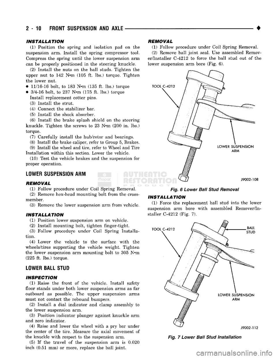
(2) Remove ball joint seal. Use assembled Remov
er/Installer C-4212 to force the ball stud out of the
lower suspension arm bore (Fig. 6).
Fig.
6
Lower
Bail
Stud
Removal
INSTALLATION (1) Force the replacement ball stud into the lower
suspension arm bore with assembled Remover/In
staller C-4212 (Fig. 7).
Fig.
7
Lower
Ball
Stud
Installation
Page 64 of 1502
•
FRONT
SUSPENSION
AND
AXLE
2 - 11 (2) Position the seal over the ball stud (if neces
sary, use a replacement seal). Force portion of the
seal downward on the ball stud housing with an ap
propriate size socket wrench until it is securely locked in place.
(3) Install lower suspension arm using procedure
under Lower Suspension Arm Installation.
LOWER SUSPENSION
ARM
BUSHING
REMOVAL (1) Follow procedure under Coil Spring and Lower
Suspension Arm Removal.
(2) Use an arbor press and an appropriate size
sleeve to force the original bushing from the lower
suspension arm bore.
INSTALLATION (1) Use an arbor press and an appropriate size
sleeve to force the replacement bushing into the
lower suspension arm bore. Ensure that it is com
pletely seated in the bore.
(2) Install the lower suspension arm according to in
structions provided within the installation procedure.
UPPER SUSPENSION
ARM REMOVAL (1) Raise the vehicle. Position support stands un
der the frame rail and lower the front of the hoist.
Remove the wheel/tire.
(2) Remove shock absorber, refer to above proce
dures.
(3) Install Spring Compressor DD-1278 (Fig. 5).
Tighten the nut finger-tight and then loosen it 1/2 of- a-turn.
(4) Remove the cotter pins and the ball stud nuts.
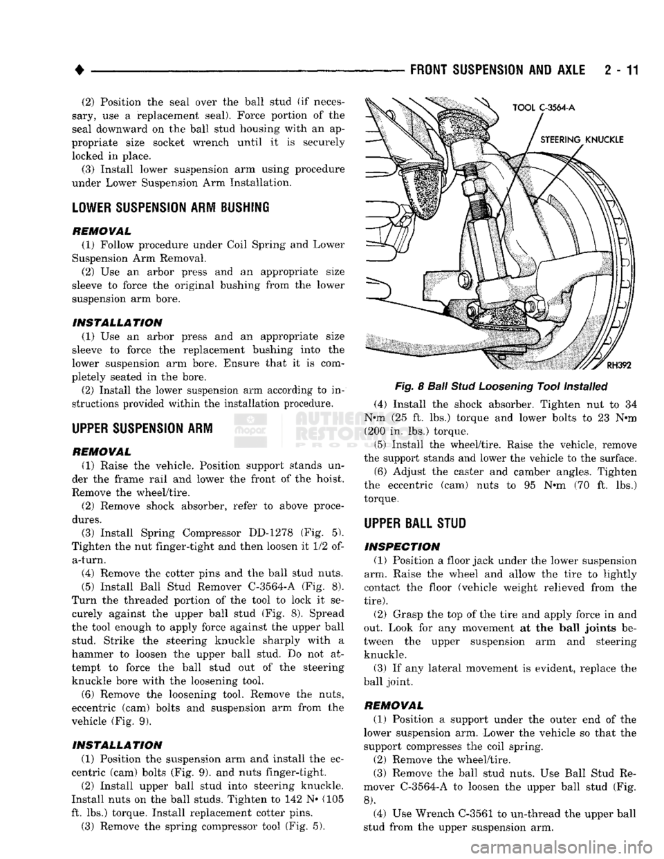
(5) Install Ball Stud Remover C^3564-A (Fig. 8).
Turn the threaded portion of the tool to lock it se curely against the upper ball stud (Fig. 8). Spread
the tool enough to apply force against the upper ball stud. Strike the steering knuckle sharply with a
hammer to loosen the upper ball stud. Do not at
tempt to force the ball stud out of the steering knuckle bore with the loosening tool.
(6) Remove the loosening tool. Remove the nuts,
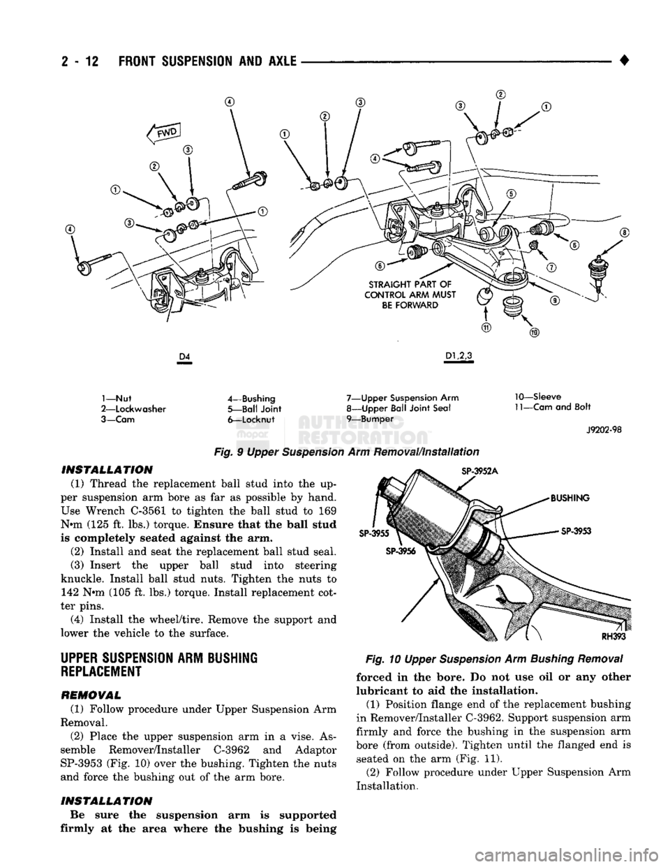
eccentric (cam) bolts and suspension arm from the
vehicle (Fig. 9).
INSTALLATION (1) Position the suspension arm and install the ec
centric (cam) bolts (Fig. 9). and nuts finger-tight.
(2) Install upper ball stud into steering knuckle.
Install nuts on the ball studs. Tighten to 142 N« (105
ft. lbs.) torque. Install replacement cotter pins.
(3) Remove the spring compressor tool (Fig. 5).
Fig.
8
Ball
Stud
Loosening
Tool Installed
(4) Install the shock absorber. Tighten nut to 34
N*m (25 ft. lbs.) torque and lower bolts to 23 N*m (200 in. lbs.) torque.
(5) Install the wheel/tire. Raise the vehicle, remove
the support stands and lower the vehicle to the surface.
(6) Adjust the caster and camber angles. Tighten
the eccentric (cam) nuts to 95 N*m (70 ft. lbs.)
torque.
UPPER BALL STUD
INSPECTION (1) Position a floor jack under the lower suspension
arm. Raise the wheel and allow the tire to lightly
contact the floor (vehicle weight relieved from the
tire).
(2) Grasp the top of the tire and apply force in and
out. Look for any movement at the ball joints be
tween the upper suspension arm and steering knuckle.
(3) If any lateral movement is evident, replace the
ball joint.
REMOVAL (1) Position a support under the outer end of the
lower suspension arm. Lower the vehicle so that the
support compresses the coil spring.
(2) Remove the wheel/tire.
(3) Remove the ball stud nuts. Use Ball Stud Re
mover C-3564-A to loosen the upper ball stud (Fig.
8).
(4) Use Wrench C-3561 to un-thread the upper ball
stud from the upper suspension arm.
Page 65 of 1502
2
- 12
FRONT
SUSPENSION
AND
AXLE
•
1—Nut
2—Lockwasher
3—Cam
4—Bushing
5—Ball Joint
6—Locknut
7—Upper
Suspension
Arm
8—Upper Ball Joint Seal
9—Bumper
10—Sleeve
11—Cam
and Bolt
J9202-98
SP-3952A
Fig.
9 Upper
Suspension
Arm Removal/Installation
INSTALLATION
(1) Thread the replacement ball stud into the up
per suspension arm bore as far as possible by hand.
Use Wrench C-3561 to tighten the ball stud to 169
N«m (125 ft. lbs.) torque. Ensure that the ball stud
is completely seated against the arm.
(2) Install and seat the replacement ball stud seal.
(3) Insert the upper ball stud into steering
knuckle. Install ball stud nuts. Tighten the nuts to 142 N#m (105 ft. lbs.) torque. Install replacement cot
ter pins.
(4) Install the wheel/tire. Remove the support and
lower the vehicle to the surface.
BUSHING
SP-3953
RH393
UPPER
SUSPENSION
ARM BUSHING
REPLACEMENT
REMOVAL
(1) Follow procedure under Upper Suspension Arm
Removal.
(2) Place the upper suspension arm in a vise. As
semble Remover/Installer C-3962 and Adaptor
SP-3953 (Fig. 10) over the bushing. Tighten the nuts and force the bushing out of the arm bore.
INSTALLATION
Be sure the suspension arm is supported
firmly at the area where the bushing is being
Fig.
10 Upper
Suspension
Arm
Bushing
Removal
forced in the bore. Do not use oil or any other
lubricant to aid the installation. (1) Position flange end of the replacement bushing
in Remover/Installer C-3962. Support suspension arm
firmly and force the bushing in the suspension arm
bore (from outside). Tighten until the flanged end is seated on the arm (Fig. 11).
(2) Follow procedure under Upper Suspension Arm
Installation.