1993 DODGE TRUCK sensor
[x] Cancel search: sensorPage 943 of 1502
14-124
FUEL SYSTEM
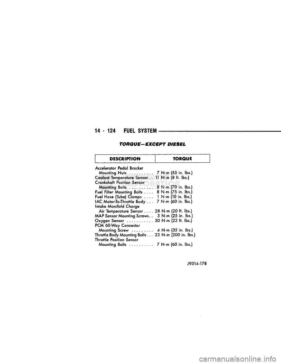
TORQUE-EXCEPT DIESEL
DESCRIPTION TORQUE
Accelerator Pedal Bracket Mounting
Nuts
. 7
N
m
(55
in.
lbs.)
Coolant Temperature Sensor . . 11
N«
m (8 ft. lbs.)
Crankshaft Position Sensor Mounting Bolts . 8
N«
m
(70 in.
lbs.)
Fuel Filter Mounting Bolts . . . . 8
N-
m
(75
in.
lbs.)
Fuel Hose (Tube) Clamps . . . . 1
N-
m
(10 in.
lbs.)
IAC Motor-To-Throttle Body . . . 7
N-
m (60 in.
lbs.)
Intake Manifold Charge (60 in.
lbs.)
Air Temperature Sensor . . . . 28
N
•m
(20 ft.
lbs.)
MAP Sensor Mounting Screws. . 3
N
•m
(25
in.
lbs.)
Oxygen Sensor . 30
N
•m
(22
ft.
lbs.)
PCM 60-Way Connector Mounting Screw . 4
N
•m
(35 in.
lbs.)
Throttle Body Mounting Bolts. . . 23
N
•m (200 in. lbs.)
Throttle Position Sensor Mounting Bolts ......... . 7
N«
m
(60 in.
lbs.)
Page 1004 of 1502
•
NV4500 MANUAL
TRANSMISSION
21 - 3
PTO
COVER
J9221-14
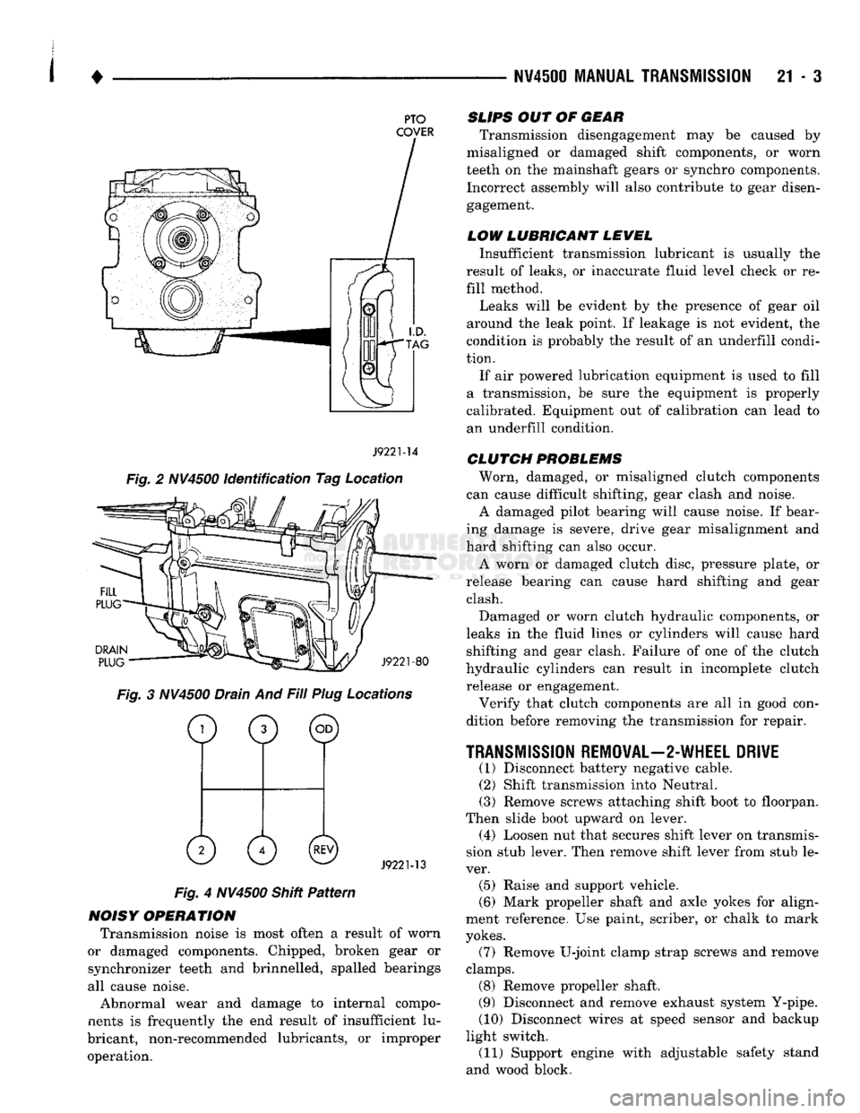
Fig. 2 NV4500 identification Tag Location
DRAIN
PLUG
J9221-80
Fig. 3 NV4500 Drain And Fill Plug Locations
o
0 ©
0 0©
J9221-13
Fig. 4 NV4500 Shitt Pattern
NOISY OPERATION Transmission noise is most often a result of worn
or damaged components. Chipped, broken gear or
synchronizer teeth and brinnelled, spalled bearings
all cause noise.
Abnormal wear and damage to internal compo
nents is frequently the end result of insufficient lu
bricant, non-recommended lubricants, or improper operation.
SLIPS
OUT OF
GEAR
Transmission disengagement may be caused by
misaligned or damaged shift components, or worn
teeth on the mainshaft gears or synchro components. Incorrect assembly will also contribute to gear disengagement.
LOW LUBRICANT LEWEL
Insufficient transmission lubricant is usually the
result of leaks, or inaccurate fluid level check or re
fill method.
Leaks will be evident by the presence of gear oil
around the leak point. If leakage is not evident, the
condition is probably the result of an underfill condi
tion.
If air powered lubrication equipment is used to fill
a transmission, be sure the equipment is properly
calibrated. Equipment out of calibration can lead to
an underfill condition.
CLUTCH
PROBLEMS
Worn, damaged, or misaligned clutch components
can cause difficult shifting, gear clash and noise.
A damaged pilot bearing will cause noise. If bear
ing damage is severe, drive gear misalignment and
hard shifting can also occur.
A worn or damaged clutch disc, pressure plate, or
release bearing can cause hard shifting and gear clash.
Damaged or worn clutch hydraulic components, or
leaks in the fluid lines or cylinders will cause hard shifting and gear clash. Failure of one of the clutch
hydraulic cylinders can result in incomplete clutch release or engagement.
Verify that clutch components are all in good con
dition before removing the transmission for repair.
TRANSMISSION
REMOVAL—2-WHEEL DRIVE
(1) Disconnect battery negative cable. (2) Shift transmission into Neutral.
(3) Remove screws attaching shift boot to floorpan.
Then slide boot upward on lever. (4) Loosen nut that secures shift lever on transmis
sion stub lever. Then remove shift lever from stub le
ver. (5) Raise and support vehicle.
(6) Mark propeller shaft and axle yokes for align
ment reference. Use paint, scriber, or chalk to mark
yokes.
(7) Remove U-joint clamp strap screws and remove
clamps. (8) Remove propeller shaft.
(9) Disconnect and remove exhaust system Y-pipe.
(10) Disconnect wires at speed sensor and backup
light switch. (11) Support engine with adjustable safety stand
and wood block.
Page 1005 of 1502
21
- 4
NV4500 MANUAL TRANSMISSION
(12) If transmission is to be disassembled for re
pair, remove drain plug and drain lubricant from transmission.
(13) move bolts/nuts attaching transmission to rear
mount.
(14) Support transmission with a transmission
jack. Secure transmission to jack with safety chains.
(15) Remove rear crossmember,
(16) Remove bolts attaching clutch slave cylinder
to clutch housing. Then move cylinder aside for
working clearance.
(17) Remove transmission harness wires from clips
on transmission shift cover. (18) Remove bolts attaching transmission to clutch
housing. (19) Slide transmission and jack rearward until
drive gear clears clutch housing. (20) Lower transmission jack and remove trans
mission from under vehicle. (21) If transmission will be overhauled, clean
transmission exterior with solvent or with steam gun.
TRANSMISSION
INSTALLATION—2-WHEEL DRIVE
(1) Apply light coat of Mopar high temperature
bearing grease to contact surfaces of following com
ponents: • drive gear splines and pilot bearing hub
• release bearing slide surface of front retainer
• pilot bearing • release bearing bore
• release fork
• release fork ball stud
• propeller shaft slip yoke (2) Fill transmission with recommended lubricant.
Correct fill level is bottom edge of fill plug hole. (3) Mount transmission on jack and position trans
mission under vehicle. (4) Raise transmission until drive gear is centered
in release bearing and clutch disc hub. (5) Move transmission forward and start drive gear
in release bearing, clutch disc and pilot bushing. (6) Work transmission forward until seated against
clutch housing. Do not allow transmission to remain
unsupported after drive gear has entered clutch disc. (7) Install and tighten transmission-to-clutch hous
ing bolts to 108 N*m (80 ft. lbs.) torque. (8) Install clutch slave cylinder. (9) Connect speed sensor and backup light switch
wires.
(10) Position transmission harness wires in clips
on shift cover. (11) Install transmission mount on transmission or
rear crossmember. (12) Install rear crossmember.
(13) Remove transmission jack and engine support
fixture. (14) Align and connect propeller shaft. (15) Fill transmission with required lubricant, if
necessary. (16) Lower vehicle.
(17) Install shift lever on transmission stub lever.
(18) Install shift boot and bezel. (19) Connect battery negative cable.
TRANSMISSION REMOVAL—4-WHEEL DRIVE
(1) Disconnect battery negative cable.
(2) Shift transmission into Neutral.
(3) Remove shift lever boot and bezel. (4) Loosen nut attaching shift lever to transmis
sion stub lever and remove shift lever from stub le
ver. (5) Raise- vehicle.
(6) Remove skid plate if equipped.
(7) If transmission will be disassembled for repair,
remove drain plug and drain lubricant from trans
mission. (8) Mark propeller shafts and yokes for assembly
reference. (9) Disconnect propeller shafts and remove propel
ler shafts. (10) Disconnect and remove exhaust system
Y-pipe. Then disconnect and lower remaining ex
haust pipes for clearance as necessary. (11) Support engine with adjustable safety stand.
(12) Disconnect speed sensor wires and disconnect
speedometer cable, if equipped. (13) Disconnect backup light switch wires.
(14) Disconnect transfer case shift linkage at
transfer case range lever. (15) Remove bolts/nuts attaching transmission to
rear support. (16) Remove crossmember bolts/nuts and remove
crossmember. (17) Support transfer case with transmission jack.
Secure transfer case to jack with safety chains. (18) Remove transfer case attaching nuts.
(19) Move transfer case rearward until input gear
clears transmission mainshaft. (20) Lower transfer case assembly and move it
from under vehicle. (21) If transmission is being removed for repair,
remove drain plug and drain lubricant from trans mission.
(22) Support transmission with transmission jack.
Secure transmission to jack with safety chains.
(23) Remove transmission harness from retaining
clips on transmission shift cover. (24) Remove bolts/nuts attaching transmission
mount to rear crossmember.
(25) Remove rear crossmember.
(26) Remove clutch slave cylinder splash shield, if
equipped.
(27) Loosen clutch slave cylinder attaching nuts
until cylinder piston rod is clear of release lever.
This reduces pressure on lever and release bearing
Page 1006 of 1502
1
.
NW4500
MANUAL
TRANSMISSION 21 - 5 making transmission removal/installation easier.
Cylinder does not have to be removed completely. (28) Remove bolts attaching transmission to clutch
housing.
(29) Move transmission rearward until drive pin
ion clears clutch disc and release bearing. (30) Lower transmission and remove it from under
vehicle.
(31) If transmission will be overhauled, thoroughly
clean transmission exterior with solvent or steam
gun.
TRANSMISSION INSTALLATION-4-WHEEL DRIVE (1) Apply light coat of Mopar high temperature
bearing grease to contact surfaces of following com
ponents: • drive gear splines and pilot bearing hub • release bearing slide surface of front retainer
• pilot bearing
• release bearing bore
• release fork
• release fork ball stud
• propeller shaft slip yoke (2) Fill transmission with recommended lubricant.
Correct level is to bottom edge of fill plug hole. (3) Mount transmission on jack and position trans
mission under vehicle. Secure transmission to jack
with safety chains. (4) Raise transmission until drive gear is centered
in release bearing and clutch disc hub. (5) Move transmission forward and start drive gear
in release bearing and clutch disc. (6) Work transmission forward until seated against
clutch housing. Do not allow transmission to remain
unsupported after drive gear has entered clutch disc. (7) Install and tighten transmission-to-clutch hous
ing bolts to 108 N*m (80 ft. lbs.) torque. (8) Connect speed sensor and backup light switch
wires.
(9) Position transmission harness wires in clips on
shift cover. (10) Tighten slave cylinder attaching nuts and in
stall slave cylinder shield, if equipped.
(11) Install transmission mount on transmission or
rear crossmember. (12) Install rear crossmember.
(13) Remove transmission jack and engine support
fixture.
(14) Install transfer case on transmission jack. Se
cure transfer case to jack with safety chains. (15) Install new gasket on transmission adapter, or
coat adapter sealing surface with Mopar Gasket
Maker, or silicone adhesive sealer.
(16) Raise jack and align transfer case input gear
with transmission mainshaft.
(17) Move transfer case forward and seat it on
adapter.
(18) Install and tighten transfer case attaching
nuts to 47 N«m (35 ft. lbs.) torque.
(19) Connect transfer case shift lever to range le
ver on transfer case. (20) Align and connect propeller shafts. Tighten
U-joint clamp strap bolts to 19 N*m (170 in. lbs.)
torque.
(21) Check lubricant levels in transmission and
transfer case. Add lubricant if necessary.
(22) Install transfer case skid plate and crossmem
ber. Tighten attaching bolts/nuts to 41 N»m (30 ft. lbs.) torque.
(23) Install exhaust system components.
(24) Lower vehicle.
(25) Install transmission shift lever, boot and be
zel.
(26) Connect battery negative cable.
Page 1052 of 1502
•
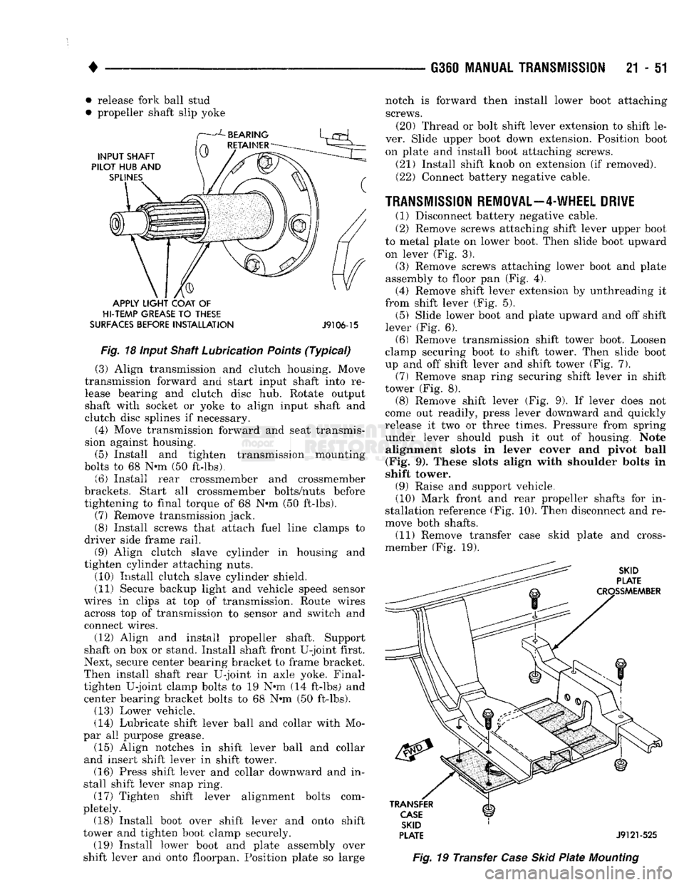
• release fork ball stud
• propeller shaft slip yoke
APPLY
LIGHT
COAT
OF
HI-TEMP
GREASE
TO
THESE
SURFACES
BEFORE
INSTALLATION
J9106-15
Fig.
18 input Shaft Lubrication
Points
(Typical)
(3) Align transmission and clutch housing. Move
transmission forward and start input shaft into re lease bearing and clutch disc hub. Rotate output
shaft with socket or yoke to align input shaft and
clutch disc splines if necessary.
(4) Move transmission forward and seat transmis
sion against housing. (5) Install and tighten transmission mounting
bolts to 68 N-m (50 ft-lbs). (6) Install rear crossmember and crossmember
brackets. Start all crossmember bolts/nuts before
tightening to final torque of 68 N»m (50 ft-lbs). (7) Remove transmission jack.
(8) Install screws that attach fuel line clamps to
driver side frame rail. (9) Align clutch slave cylinder in housing and
tighten cylinder attaching nuts. (10) Install clutch slave cylinder shield.
(11) Secure backup light and vehicle speed sensor
wires in clips at top of transmission. Route wires across top of transmission to sensor and switch and
connect wires.
(12) Align and install propeller shaft. Support
shaft on box or stand. Install shaft front U-joint first.
Next, secure center bearing bracket to frame bracket.
Then install shaft rear U-joint in axle yoke. Final- tighten U-joint clamp bolts to 19 N@m (14 ft-lbs) and center bearing bracket bolts to 68 N»m (50 ft-lbs). (13) Lower vehicle.
(14) Lubricate shift lever ball and collar with Mo
par all purpose grease. (15) Align notches in shift lever ball and collar
and insert shift lever in shift tower. (16) Press shift lever and collar downward and in
stall shift lever snap ring. (17) Tighten shift lever alignment bolts com
pletely. (18) Install boot over shift lever and onto shift
tower and tighten boot clamp securely. (19) Install lower boot and plate assembly over
shift lever and onto floorpan. Position plate so large G360
MANUAL TRANSMISSION
21 - 51
SKID
PLATE
J9121-525
Fig.
19 Transfer
Case
Skid
Plate
Mounting
notch is forward then install lower boot attaching
screws. (20) Thread or bolt shift lever extension to shift le
ver. Slide upper boot down extension. Position boot on plate and install boot attaching screws.
(21) Install shift knob on extension (if removed). (22) Connect battery negative cable.
TRANSMISSION REMOVAL—4-WHEEL DRIVE
(1) Disconnect battery negative cable.
(2) Remove screws attaching shift lever upper boot
to metal plate on lower boot. Then slide boot upward on lever (Fig. 3).
(3) Remove screws attaching lower boot and plate
assembly to floor pan (Fig. 4). (4) Remove shift lever extension by unthreading it
from shift lever (Fig. 5). (5) Slide lower boot and plate upward and off shift
lever (Fig. 6). (6) Remove transmission shift tower boot. Loosen
clamp securing boot to shift tower. Then slide boot
up and off shift lever and shift tower (Fig. 7).
(7)
Remove snap ring securing shift lever in shift
tower (Fig. 8). (8) Remove shift lever (Fig. 9). If lever does not
come out readily, press lever downward and quickly
release it two or three times. Pressure from spring under lever should push it out of housing. Note alignment slots in lever cover and pivot ball
(Fig. 9). These slots align with shoulder bolts in
shift tower.
(9) Raise and support vehicle.
(10) Mark front and rear propeller shafts for in
stallation reference (Fig. 10). Then disconnect and re
move both shafts. (11) Remove transfer case skid plate and cross-
member (Fig. 19).
Page 1053 of 1502
21 - 52 G360
MANUAL
TRANSMISSION
• (12) Disconnect wires at vehicle speed sensor and
backup light switch.
(13) Disconnect transfer case shift lever from lever
on transfer case.
(14) Temporarily support transmission with adjust
able jack stand. Then support transfer case with
transmission jack.
(15) Remove nuts attaching transfer case to trans
mission adapter and move transfer case away from
transmission rear retainer.
(16) Lower transfer case and move it from under
vehicle. Remove transfer case from transmission jack and place transfer case on workbench.
(17) Support transmission with transmission jack.
Secure transmission to jack with safety chains. Then
remove jack stand previously used to support trans
mission.
(18) Spread clamps that secure switch wires to
transmission top cover and remove wires from clamps. Move wires aside to protect them and pro
vide working clearance.
(19) Remove bolts attaching transmission rear
mount to crossmember.
(20) On some models, it is necessary to remove
screws attaching fuel line clamps to driver side
frame rail. Three clamps must be removed to so fuel lines can be moved for access to crossmember bolts at
this side of frame rail.
(21) Remove left and right crossmember-to-frame
braces and remove crossmember.
(22) Remove clutch slave cylinder shield.
(23) Loosen clutch slave cylinder attaching nuts
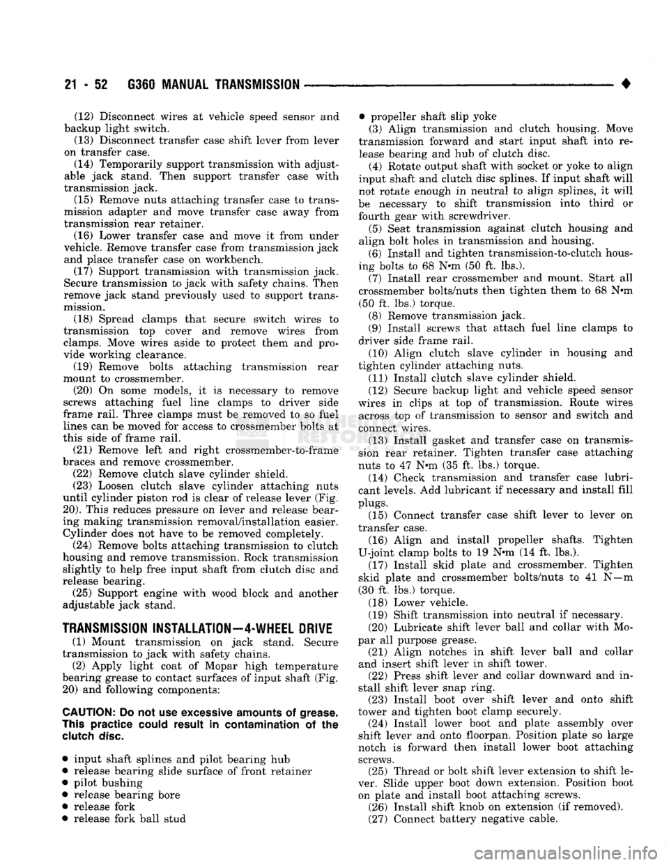
until cylinder piston rod is clear of release lever (Fig.
20).
This reduces pressure on lever and release bear
ing making transmission removal/installation easier. Cylinder does not have to be removed completely.
(24) Remove bolts attaching transmission to clutch
housing and remove transmission. Rock transmission slightly to help free input shaft from clutch disc and
release bearing.
(25) Support engine with wood block and another
adjustable jack stand.
TRANSMISSION
INSTALLATION—4-WHEEL
DRIVE
(1) Mount transmission on jack stand. Secure
transmission to jack with safety chains.
(2) Apply light coat of Mopar high temperature
bearing grease to contact surfaces of input shaft (Fig. 20) and following components:
CAUTION:
Do not use
excessive
amounts
of
grease.
This
practice
could
result in contamination of the
clutch
disc.
• input shaft splines and pilot bearing hub
• release bearing slide surface of front retainer
• pilot bushing
• release bearing bore
• release fork
• release fork ball stud • propeller shaft slip yoke
(3) Align transmission and clutch housing. Move
transmission forward and start input shaft into re lease bearing and hub of clutch disc. (4) Rotate output shaft with socket or yoke to align
input shaft and clutch disc splines. If input shaft will
not rotate enough in neutral to align splines, it will
be necessary to shift transmission into third or fourth gear with screwdriver. (5) Seat transmission against clutch housing and
align bolt holes in transmission and housing. (6) Install and tighten transmission-to-clutch hous
ing bolts to 68 N-m (50 ft. lbs.). (7) Install rear crossmember and mount. Start all
crossmember bolts/nuts then tighten them to 68 N*m (50 ft. lbs.) torque. (8) Remove transmission jack.
(9) Install screws that attach fuel line clamps to
driver side frame rail. (10) Align clutch slave cylinder in housing and
tighten cylinder attaching nuts. (11) Install clutch slave cylinder shield.
(12) Secure backup light and vehicle speed sensor
wires in clips at top of transmission. Route wires across top of transmission to sensor and switch and
connect wires.
(13) Install gasket and transfer case on transmis
sion rear retainer. Tighten transfer case attaching
nuts to 47 N-m (35 ft. lbs.) torque. (14) Check transmission and transfer case lubri
cant levels. Add lubricant if necessary and install fill
plugs.
(15) Connect transfer case shift lever to lever on
transfer case.
(16) Align and install propeller shafts. Tighten
U-joint clamp bolts to 19 N-m (14 ft. lbs.). (17) Install skid plate and crossmember. Tighten
skid plate and crossmember bolts/nuts to 41 N—m
(30 ft. lbs.) torque.
(18) Lower vehicle.
(19) Shift transmission into neutral if necessary.
(20) Lubricate shift lever ball and collar with Mo
par all purpose grease. (21) Align notches in shift lever ball and collar
and insert shift lever in shift tower. (22) Press shift lever and collar downward and in
stall shift lever snap ring. (23) Install boot over shift lever and onto shift
tower and tighten boot clamp securely. (24) Install lower boot and plate assembly over
shift lever and onto floorpan. Position plate so large
notch is forward then install lower boot attaching screws. (25) Thread or bolt shift lever extension to shift le
ver. Slide upper boot down extension. Position boot on plate and install boot attaching screws. (26) Install shift knob on extension (if removed).
(27) Connect battery negative cable.
Page 1083 of 1502
21
- 82
AUTOMATIC TRANSMISSION—32RH/36RH/37RH/42RH/46RH
————— •
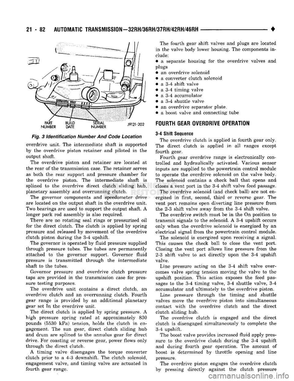
PART
NUMBER BUILD
DATE SERIAL
NUMBER The fourth gear shift valves and plugs are located
in the valve body lower housing. The components in
clude:
• a separate housing for the overdrive valves and
plugs • an overdrive solenoid
• a converter clutch solenoid
• a 3-4 shift valve
• a 3-4 timing valve
• a 3-4 accumulator • a 3-4 shuttle valve
• an overdrive separator plate. • a boost valve and connecting tube
J9121-202
FOURTH GEAR OVERDRIVE OPERATION Fig.
3
Identification
Number
And
Code
Location
overdrive unit. The intermediate shaft is supported
by the overdrive piston retainer and piloted in the output shaft.
The overdrive piston and retainer are located at
the rear of the transmission case. The retainer serves as both the rear support and pressure chamber for
the overdrive piston. The intermediate shaft is splined to the overdrive direct clutch sliding hub,
planetary assembly and overrunning clutch.
The governor components and speedometer drive
are located on the output shaft in the overdrive unit.
Two bearings are used to support the output shaft. A longer park rod assembly is also required.
There are no rotating seal rings or pressurized oil
for the direct clutch. The clutch is applied by spring
pressure and released by movement of the overdrive clutch piston during the 3-4 upshift.
The governor is operated by fluid pressure supplied
through pressure tubes. The tubes are permanently attached to the governor support. Governor fluid
pressure is transmitted through the intermediate shaft to the tubes.
Governor pressure and overdrive clutch pressure
taps are provided in the transmission case for pres sure testing purposes.
The overdrive unit contains a direct clutch, an
overdrive clutch and an overrunning clutch. Fourth
gear range is provided by an additional planetary
gear set In the overdrive unit.
The direct clutch is applied by spring pressure. A
high pressure spring rated at approximately 830
pounds (5530 kPa) tension, holds the clutch in en gagement. The sun gear, direct clutch sliding hub
and drum are splined to the annulus gear for direct
drive. For coasting or reverse gear, power flows only
through the direct clutch.
A timing valve disengages the torque converter
clutch prior to a 4-3 downshift. The clutch solenoid, engagement valve, and timing valve are actuated in
fourth gear range. 3-4
Shift
Sequence
The overdrive clutch is applied in fourth gear only.
The direct clutch is applied in all ranges except
fourth gear.
Fourth gear overdrive range is electronically con
trolled and hydraulically activated. Various sensor inputs are supplied to the powertrain control module
to operate the overdrive solenoid on the valve body. The solenoid contains a check ball that opens and closes a vent port in the 3-4 shift valve feed passage.
The overdrive solenoid (and check ball) are not en
ergized in first, second, third or reverse gear. The
vent port remains open diverting line pressure from
the 2-3 shift valve away from the 3-4 shift valve.
The overdrive switch must be in the On position to
transmit signals to the solenoid. A 3-4 upshift occurs only when the overdrive solenoid is energized by an electrical signal from the powertrain control module. The solenoid is energized upon receiving a signal.
This causes the check ball to close the vent port. Closing the vent port allows line pressure from the
2-3 shift valve to act directly upon the 3-4 upshift
valve.
Line pressure acting on the 3-4 shift valve over
comes valve spring tension moving the valve to the
upshift position. This action exposes the feed pas sages to the 3-4 timing valve, 3-4 shuttle valve, 3-4 accumulator and ultimately to the overdrive piston.
Line pressure through the timing and shuttle
valves move the overdrive piston into simultaneous
contact with the overdrive clutch and the direct clutch sliding hub.
The overdrive clutch is engaged and the direct
clutch is disengaged simultaneously to complete the 3-4 upshift.
The boost valve provides increased fluid apply pres
sure to the overdrive clutch during the 3-4 upshift and during fourth gear operation. The amount of
boost is determined by throttle opening and line pressure.
The overdrive piston engages the overdrive clutch
by pressing directly against the clutch pressure
Page 1084 of 1502
•
AUTOMATIC TRANSiISSIO|-32RH/8iRH/37RH/42RH/4iRH
21 - 83 plate. The overdrive clutch also disengages the direct
clutch during 3-4 upshifts. As fluid pressure extends
the overdrive piston, the piston contacts the direct clutch hub pressing it rearward. This action com
presses the direct clutch spring relieving spring load on the clutch pack. The clutch is disengaged once
spring load is relieved.
The 3-4 accumulator cushions overdrive clutch en
gagement to smooth the transition into fourth gear.
The accumulator is charged at the same time as ap
ply pressure acts against the overdrive piston.
Converter clutch engagement in overdrive fourth
gear is controlled by sensor inputs to the powertrain
control module. In third gear above 25 mph, sensor inputs to the control module that determine clutch
engagement and shift timing are:
• coolant temperature (verifies minimum of 60° F)
• engine speed • vehicle speed
• throttle position
• manifold vacuum (MAP sensor)
Gearshift
Mechanism
The gear shift mechanism provides the same shift
positions used with 3-speed Chrysler transmissions
(P-R-N-D-2-1).
The shift into overdrive fourth gear range occurs
only after the transmission has completed the shift into D third gear range. No further movement of the
shift mechanism is required to complete the 3-4 shift.
The fourth gear upshift occurs automatically when
the overdrive control switch is in the ON position. Shift timing is determined by sensor inputs to the
engine controller.
Overdrive Control
Switch
The overdrive control switch is located in the in
strument panel. In the On position, automatic shifts
into fourth gear overdrive will occur. In the Off posi
tion, the switch overrides the engine controller pre
venting a shift to overdrive fourth gear range.
The switch has an indicator light that illuminates
when overdrive is turned off. The switch also resets
when the ignition key is turned to the OFF position so that the automatic overdrive feature is restored.
The use of fault codes is employed to help diagnose
the electronic components that operate the overdrive
unit and converter clutch.
HYDRAULIC
CONTROLS
The 42REJ/46RH hydraulic control system provides
fully automatic operation. The system performs five
basic functions which are: pressure supply, pressure regulation, flow control, clutch/band application, and
lubrication. 42RH/46RH system operation is similar to that de
scribed in the 32RH/36RH/37RH General Informa tion section. The main difference being fourth gear
operation which is covered here.
Pressure
Regulation
The pressure regulator valve maintains line pres
sure.
The amount of pressure developed is controlled
by throttle pressure which is dependent on the de gree of throttle opening. The regulator valve is lo
cated in the valve body.
The throttle valve determines line pressure and
shift speed. Governor pressure increases in propor
tion to vehicle speed. The throttle valve controls up shift and downshift speeds by regulating pressure
according to throttle position.
Flow
Control And Lubrication The manual valve is operated by the gearshift link
age and provides the operating range selected by the
driver.
The 1-2 shift valve provides 1-2 or 2-1 shifts and
the 2-3 shift valve provides 2-3 or 3-2 shifts.
The kickdown valve provides forced 3-2 or 3-1
downshifts depending on vehicle speed. Downshifts
occur when the throttle is opened beyond downshift
detent position which is just before wide open throt
tle.
The 2-3 valve throttle pressure plug provides 3-2
downshifts at varying throttle openings depending on
vehicle speed.
The 1-2 shift control valve transmits 1-2 shift pres
sure to the accumulator piston. This controls kick-
down band capacity on 1-2 upshifts and 3-2 downshifts.
The 3-4 shift valve, shuttle valve, timing valve and
accumulator are only actuated when the overdrive
solenoid is energized.
The solenoid contains a check ball that controls a
vent port to the 3-4 valve. The check ball either di
verts line pressure away from or directly to, the 3-4 shift valve. Energizing the solenoid causes the check
ball to close the vent port allowing line pressure to act upon the 3-4 upshift valve.
The limit valve determines maximum speed at
which a 3-2 part throttle kickdown can be made. Some transmissions do not have the limit valve and
maximum speed for a 3-2 kickdown is at the detent
position.
The 2-3 shuttle valve has two functions. First is
fast front band release and smooth engagement dur ing lift-foot 2-3 upshifts. The second is to regulate
front clutch and band application during 3-2 down
shifts.
The 3-4 shuttle valve uses a combination of throt
tle and governor pressure to control the rate of over
drive piston apply and release. This is done to
maintain shift quality at varying throttle openings.