1993 DODGE TRUCK sensor
[x] Cancel search: sensorPage 908 of 1502
FUEL
SYSTEM
14-89
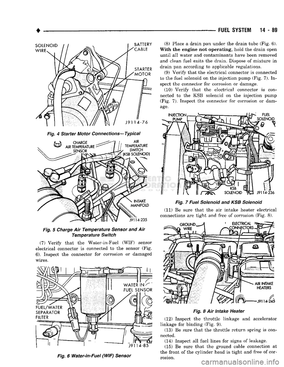
Fig.
4 Starter Motor Connections—Typical
Fig.
5
Charge
Air
Temperature
Sensor
and Air
Temperature
Switch
(7) Verify that the Water-in-Fuel (WIF) sensor
electrical connector is connected to the sensor (Fig.
6).
Inspect the connector for corrosion or damaged
wires.
Fig.
6 Water-in-Fuel (WIF)
Sensor
(8) Place a drain pan under the drain tube (Fig. 6).
With the engine not operating, hold the drain open
until all water and contaminants have been removed and clean fuel exits the drain. Dispose of mixture in
drain pan according to applicable regulations.
(9) Verify that the electrical connector is connected
to the fuel solenoid on the injection pump (Fig. 7). In spect the connector for corrosion or damage.
(10) Verify that the electrical connector is con
nected to the KSB solenoid on the injection pump (Fig. 7). Inspect the connector for corrosion or dam
age.
Fig.
8 Air Intake Heater
(12) Inspect the throttle linkage and accelerator
linkage for binding (Fig. 9).
(13) Be sure that the throttle return spring is con
nected. (14) Inspect all fuel lines for signs of leakage.
(15) Be sure that the ground cable connection at
the front of the cylinder head is tight and free of cor rosion.
Page 910 of 1502
(3) Check for battery voltage at both intake air
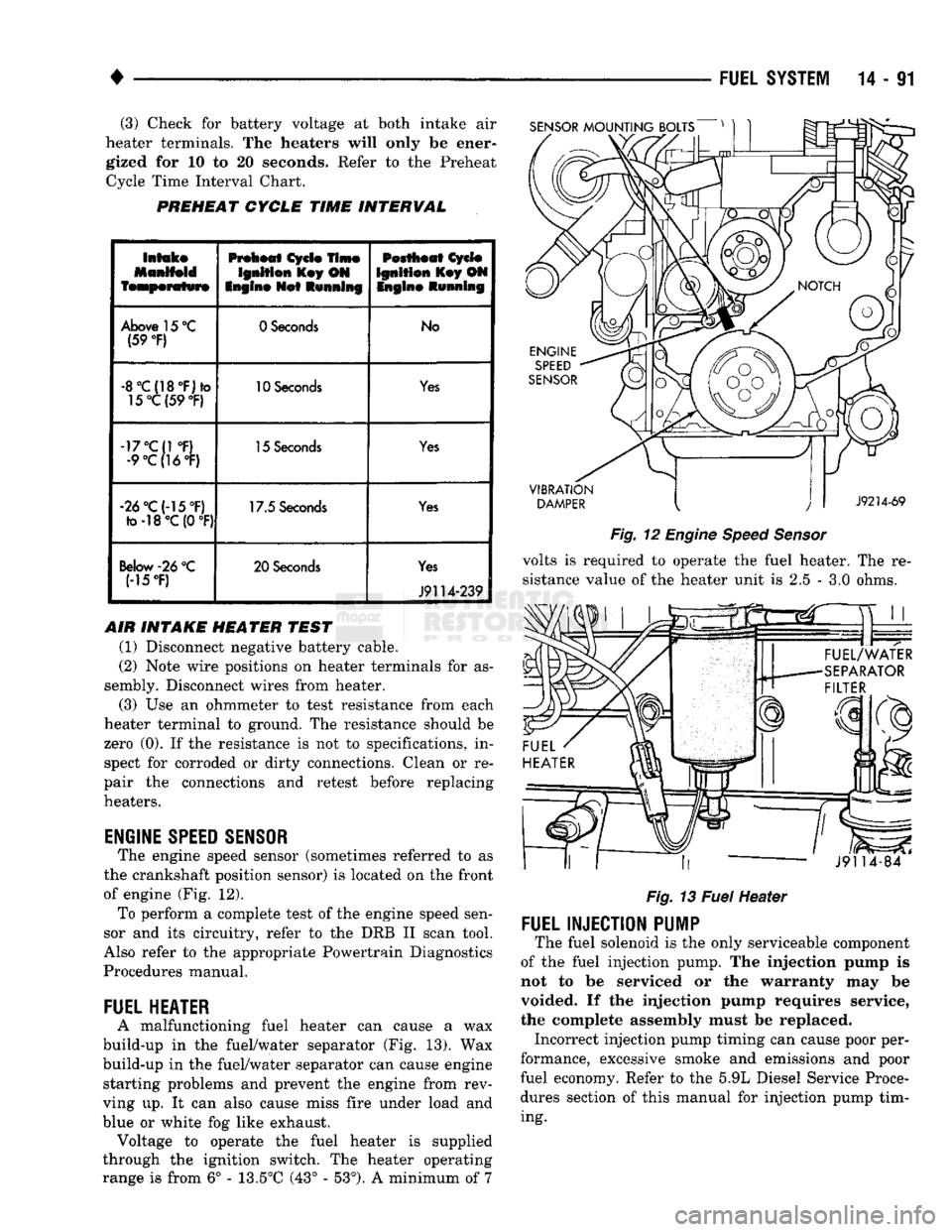
heater terminals. The heaters will only be ener gized for 10 to 20 seconds. Refer to the Preheat Cycle Time Interval Chart.
PREHEAT
CYCLE
TIME
INTERVAL
SENSOR
MOUNTING
BOLTS
Intake
Manifold
temperature
Preheat
Cycle
Time
Ignition
Key ON
Engine
Net
Running
Pestheat
Cycle
Ignition
Key ON Ingin©
Running
Above 15 °C (59
°F)
0 Seconds
No
-8°C{18°F)*o 15°C(59
°F)
10 Seconds
Yes
-17°C{1 °F) •9°C(16°F) 15 Seconds
Yes
-26°C(-15°F) fo-18°C (0
°F)
17.5 Seconds
Yes
Below
-26
°C
(15T) 20 Seconds
Yes
J9114-239
AIR INTAKE HEATER TEST (1) Disconnect negative battery cable.
(2) Note wire positions on heater terminals for as
sembly. Disconnect wires from heater.
(3) Use an ohmmeter to test resistance from each
heater terminal to ground. The resistance should be
zero (0). If the resistance is not to specifications, in spect for corroded or dirty connections. Clean or re
pair the connections and retest before replacing
heaters.
ENGINE
SPEED
SENSOR
The engine speed sensor (sometimes referred to as
the crankshaft position sensor) is located on the front
of engine (Fig. 12). To perform a complete test of the engine speed sen
sor and its circuitry, refer to the DRB II scan tool.
Also refer to the appropriate Powertrain Diagnostics
Procedures manual.
FUEL
HEATER
A malfunctioning fuel heater can cause a wax
build-up in the fuel/water separator (Fig. 13). Wax
build-up in the fuel/water separator can cause engine starting problems and prevent the engine from rev
ving up. It can also cause miss fire under load and
blue or white fog like exhaust. Voltage to operate the fuel heater is supplied
through the ignition switch. The heater operating
range is from 6° - 13.5°C (43° - 53°). A minimum of 7
VIBRATION
DAMPER
J9214-69
Fig.
12
Engine
Speed
Sensor
volts is required to operate the fuel heater. The re
sistance value of the heater unit is 2.5 - 3.0 ohms.
««.
* rr ,,
J9114-84
Fig.
13
Fuel
Heater
FUEL
INJECTION
PUMP
The fuel solenoid is the only serviceable component
of the fuel injection pump. The injection pump is
not to be serviced or the warranty may be
voided. If the injection pump requires service,
the complete assembly must be replaced. Incorrect injection pump timing can cause poor per
formance, excessive smoke and emissions and poor
fuel economy. Refer to the 5.9L Diesel Service Proce
dures section of this manual for injection pump tim
ing.
Page 913 of 1502
14
- 94
FUEL
SYSTEM
•
THROTTLE POSITION
SENSOR
TEST
CAUTION;
Before checking
the
TPS,
the
throttle
linkage must
be
checked
for
correct
adjustment.
The
throttle
lever must
contact
the low idle
speed screw.
The
throttle
lever must reach breakover when
the
throttle
is
wide
open. Refer
to the
Accelerator Pedal and
Throttle
Cable section
of
Group
14,
Fuel Systems.
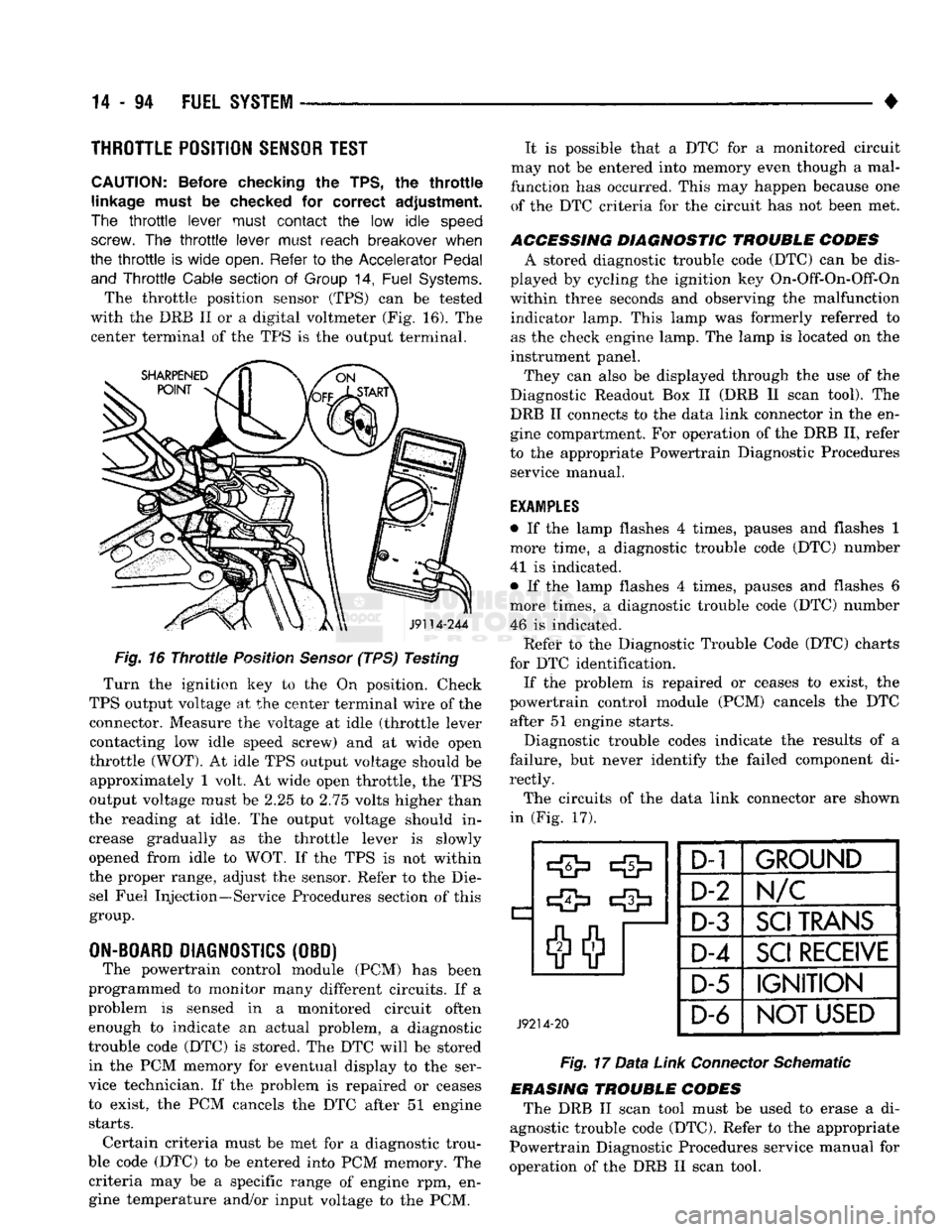
The throttle position sensor (TPS) can be tested
with the DRB II or a digital voltmeter (Fig. 16). The center terminal of the TPS is the output terminal.
J9114-244
Fig.
16
Throttle
Position
Sensor
(TPS) Testing
Turn the ignition key to the On position. Check
TPS output voltage at the center terminal wire of the connector. Measure the voltage at idle (throttle lever contacting low idle speed screw) and at wide open
throttle
(WOT).
At idle TPS output voltage should be approximately 1 volt. At wide open throttle, the TPS
output voltage must be 2.25 to 2.75 volts higher than
the reading at idle. The output voltage should in
crease gradually as the throttle lever is slowly
opened from idle to WOT. If the TPS is not within
the proper range, adjust the sensor. Refer to the Die sel Fuel Injection—Service Procedures section of this
group.
ON-BOARD
DIAGNOSTICS
(OBD) The powertrain control module (PCM) has been
programmed to monitor many different circuits. If a
problem is sensed in a monitored circuit often enough to indicate an actual problem, a diagnostic
trouble code (DTC) is stored. The DTC will be stored in the PCM memory for eventual display to the ser
vice technician. If the problem is repaired or ceases
to exist, the PCM cancels the DTC after 51 engine
starts.
Certain criteria must be met for a diagnostic trou
ble code (DTC) to be entered into PCM memory. The criteria may be a specific range of engine rpm, engine temperature and/or input voltage to the PCM. It is possible that a DTC for a monitored circuit
may not be entered into memory even though a mal
function has occurred. This may happen because one of the DTC criteria for the circuit has not been met.
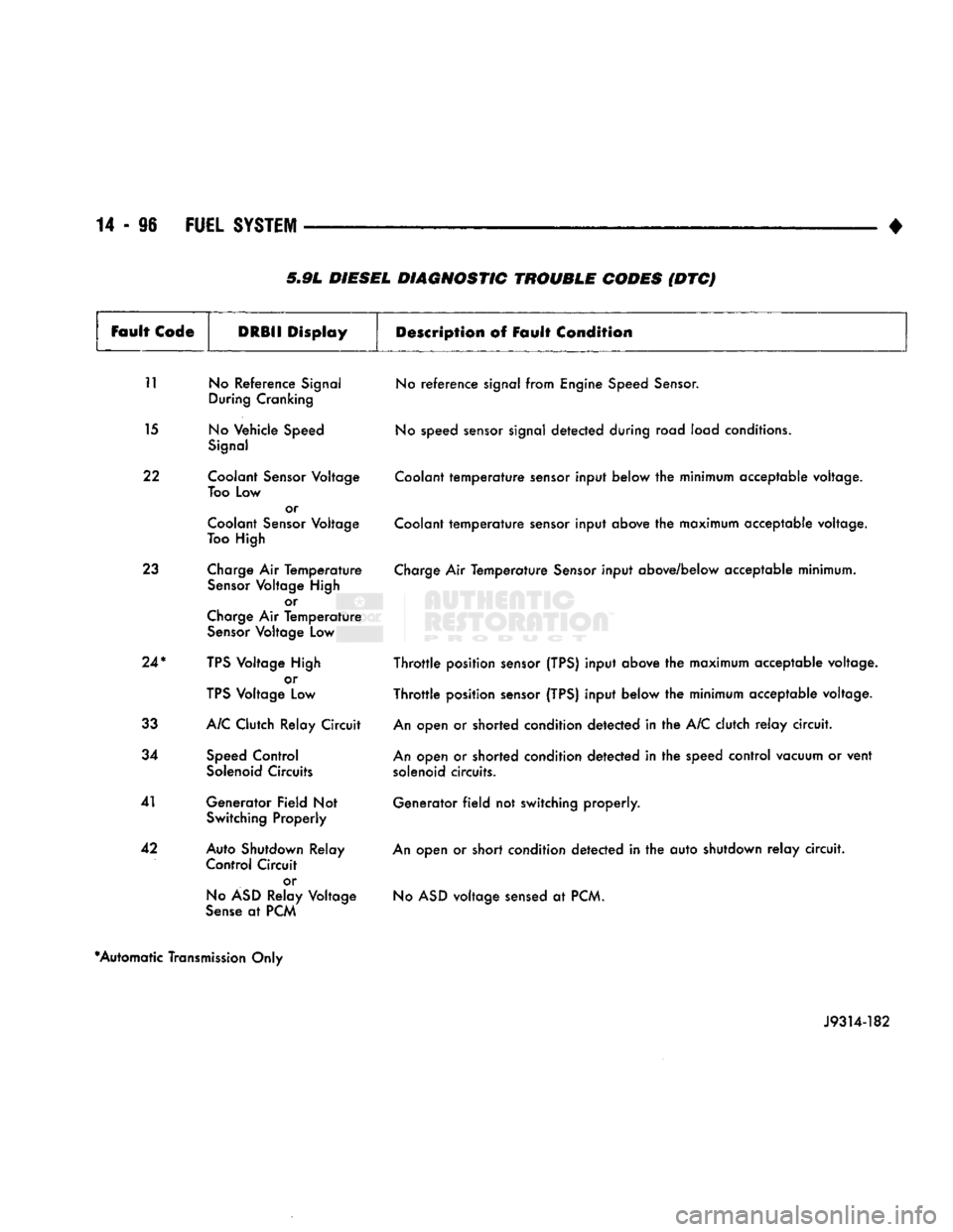
ACCESSING DIAGNOSTIC TROUBLE CODES A stored diagnostic trouble code (DTC) can be dis
played by cycling the ignition key On-Off-On-Off-On
within three seconds and observing the malfunction indicator lamp. This lamp was formerly referred to
as the check engine lamp. The lamp is located on the
instrument panel.
They can also be displayed through the use of the
Diagnostic Readout Box II (DRB II scan tool). The
DRB II connects to the data link connector in the en
gine compartment. For operation of the DRB II, refer
to the appropriate Powertrain Diagnostic Procedures service manual.
EXAMPLES
• If the lamp flashes 4 times, pauses and flashes 1
more time, a diagnostic trouble code (DTC) number
41 is indicated.
• If the lamp flashes 4 times, pauses and flashes 6
more times, a diagnostic trouble code (DTC) number 46 is indicated. Refet* to the Diagnostic Trouble Code (DTC) charts
for DTC identification. If the problem is repaired or ceases to exist, the
powertrain control module (PCM) cancels the DTC after 51 engine starts.
Diagnostic trouble codes indicate the results of a
failure, but never identify the failed component di
rectly.
The circuits of the data link connector are shown
in (Fig. 17).
J9214-20
D-1
1
GROUND
D-2
N/C
D-3
SCI
TRANS
D-4
SCI
RECEIVE
D-5 IGNITION
D-6
NOT USED
Fig.
17
Data
Link
Connector
Schematic
ERASING TROUBLE CODES The DRB II scan tool must be used to erase a di
agnostic trouble code (DTC). Refer to the appropriate
Powertrain Diagnostic Procedures service manual for
operation of the DRB II scan tool.
Page 915 of 1502
5.9L DIESEL DIAGNOSTIC TROUBLE CODES (DTC)
Fault
Code
DRBII
Display
Description
of Fault
Condition
11 No Reference Signal During Cranking
15 No Vehicle Speed Signal
22 Coolant Sensor Voltage Too Low or
Coolant Sensor Voltage
Too High
23 Charge Air Temperature Sensor Voltage High or
Charge Air Temperature Sensor Voltage Low
24*
TPS Voltage High or
TPS Voltage Low
33 A/C Clutch Relay Circuit
34 Speed Control Solenoid Circuits
41 Generator Field Not Switching Properly
42 Auto Shutdown Relay Control Circuit
or
No ASD Relay Voltage
Sense at PCM No reference signal from Engine Speed Sensor.
No speed sensor signal detected during road load conditions.
Coolant temperature sensor input below the minimum acceptable voltage.
Coolant temperature sensor input above the maximum acceptable voltage.
Charge Air Temperature Sensor input above/below acceptable minimum.
Throttle position sensor (TPS) input above the maximum acceptable voltage.
Throttle position sensor (TPS) input below the minimum acceptable voltage.
An open or shorted condition detected in the A/C clutch relay circuit.
An open or shorted condition detected in the speed control vacuum or vent solenoid circuits.
Generator field not switching properly.
An open or short condition detected in the auto shutdown relay circuit. No ASD voltage sensed at PCM.
*Automatic Transmission Only
J9314-182
Page 918 of 1502
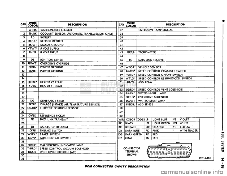
CAV
WIRE
COLOR DESCRIPTION
CAV
WIRE
COLOR DESCRIPTION
1 WT/BK
WATER-IN-FUEL SENSOR 37 OVERDRIVE LAMP SIGNAL
2 TN/BK
COOLANT SENSOR (AUTOMATIC TRANSMISSION ONLY) 38
3 RD BATTERY
39
4
BK/LB*
SENSOR RETURN 40
5 BK/WT
SIGNAL GROUND 41
6 VT/WT*
5 VOLT SUPPLY 42
7 TN/YL 8 VOLT INPUT 43 GR/LB TACHOMETER
8 44
9 DB
IGNITION SENSE 45 LG DATA LINK RECIEVE
10 RD/WT*
OVERDRIVE OVERRIDE 46
11 BK/TN POWER GROUND
47 WT/OR* VEHICLE SENSOR
12 BK/TN
POWER GROUND 48 BR/RD* SPEED CONTROL COAST/SET SWITCH
13 49 YL/RD* SPEED CONTROL ON/OFF SWITCH
14 50 WT/LG* SPEED CONTROL RESUME/ACCEL SWITCH
15 OR/BK* HEATER
#2
RELAY 51 DB/YL ASD RELAY
16 YL/BK HEATER #1 RELAY 52
17 53 LG/RD* SPEED CONTROL VENT SOLENOID
18 54 BK/PK* WATER-IN-FUEL LAMP
19 55 OR/LG* OVERDRIVE SOLENOID
20 DG GENERATOR FIELD 56 DG/WT WAIT-TO-START LAMP
21 BK/RD
CHARGE (INTAKE) AIR TEMPERATURE SENSOR 57 DG/OR ASD SENSE
22
OR/DB*
THROTTLE POSITION SENSOR 58
23 59
24 GY/BK
REFERENCE PICKUP 60
25 PK
DATA LINK TRANSMIT WIRE COLOR CODES LB
LIGHT BLUE VT VIOLET
26 BK BLACK LG LIGHT GREEN WT
WHITE
27 BR
A/C CLUTCH REQUEST BR BROWN OR ORANGE
YL YELLOW
28 LG/RD THERMO SWITCH DB DARK BLUE PK PINK *
WITH TRACER
29 WT/PK* BRAKE SWITCH DG DARK GREEN
RD RED
30 BR/YL*
PARK/NEUTRAL SWITCH GY GRAY TN TAN
31 ruin
32 BK/PK*
MALFUNCTION INDICATOR LAMP
n
33 TN/RD*
SPEED CONTROL VACUUM SOLENOID CONNECTOR
J//000OOOOOOO
1 1
HI
173456789
10 J/^"*\
Hi
oooooooooo (1 Oj]
VlX
21
22
23
24
25
26
27
28
29
30
\V~V//
oooooooooo
\
II
12 13
14 15
16 17 18
19 20
\
34 DB/OR
WIDE OPEN THROTTLE (A/C) TERMINAL
J//000OOOOOOO
1 1
HI
173456789
10 J/^"*\
Hi
oooooooooo (1 Oj]
VlX
21
22
23
24
25
26
27
28
29
30
\V~V//
oooooooooo)}
31
32 33 34 35 36 37 38 39 40
1JU
35 SHOWN \\\
41 42 43 44 45 46 47 48 49
SO
1
^m^^
|
oooooooooo
1
1
oooooooooo
J//
36
Li
J9314-185
PCM
CONNECTOR CAVITY DESCRIPTION
Page 925 of 1502
14
- 106
FUEL SYSTEi
DIESEL FUEL
INJECTION-SERVICE
PROCEDURES
INDEX
page
Air Bleed Procedure
106
Air Fuel Control Tube
107
Air Intake Heater
107
Engine
Speed
Sensor
108
Fuel Drain Manifold
109
Fuel Heater
. 110
Fuel
Injection
Pump
110
Fuel
Injection
Pump Supply Line
114
Fuel
Injectors
114
AIR BLEED PROCEDURE
A certain amount
of air
becomes trapped
in the
fuel system when fuel system components
are
ser
viced
or
replaced. Bleed
the
system after fuel system service according
to the
following procedures.
WARNING:
DO NOT
BLEED
AIR
FROM
THE
FUEL
SYSTEM
OF
A
HOT
ENGINE.
DO
NOT
ALLOW FUEL
TO SPRAY ONTO
THE
EXHAUST MANIFOLD WHEN BLEEDING
AIR
FROM
THE
FUEL SYSTEM.
MANUAL BLEEDING
Some
air
enters
the
fuel system when
the
filters
or
injection pump supply line
are
changed. This small
amount
of air is
vented automatically from
the
injec
tion pump through
the
fuel drain manifold. This
is if
the filter
was
changed according
to
instructions.
The system will have
to be
bleed manually
if:
•
The
fuel filter
is not
filled before installation
•
Injection pump
is
replaced
•
High pressure fuel line connections
are
loosened
or
lines replaced
•
Initial engine start-up
or
start-up after
an ex
tended period
of no
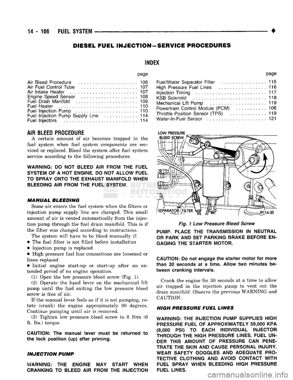
engine operation. (1) Open
the low
pressure bleed screw
(Fig. 1).
(2) Operate
the
hand lever
on the
mechanical lift
pump until
the
fuel exiting
the low
pressure bleed screw
is
free
of air.
If
the
manual lever feels
as if it is not
pumping,
ro
tate (crank)
the
engine approximately
90
degrees. Continue pumping until
air is
removed. (3) Tighten
low
pressure bleed screw
to 8 N»m (6
ft.
lbs.)
torque.
CAUTION:
The
manual lever must
be
returned
to
the lock position
(up) after
priming.
INJECTION
PUMP
WARNING:
THE
ENGINE
MAY
START WHEN
CRANKING
TO
BLEED
AIR
FROM
THE
INJECTION
page
Fuel/Water Separator
Filter
................
115
High
Pressure Fuel Lines
116
Injection
Timing
117
KSB
Solenoid
118
Mechanical
Lift
Pump
119
Powertrain Control Module (PCM)
108
Throttle
Position
Sensor
(TPS)
119
Water-ln-Fuel
Sensor
121
Fig.
1
Low
Pressure
Bleed Screw
PUMP.
PLACE
THE
TRANSMISSION
IN
NEUTRAL
OR
PARK
AND SET
PARKING BRAKE BEFORE
EN
GAGING
THE
STARTER MOTOR.
CAUTION:
Do
not
engage
the
starter
motor
for
more
than
30
seconds
at a
time.
Allow
two
minutes
be
tween cranking intervals.
Crank
the
engine
for 30
seconds
at a
time
to
allow
air trapped
in the
injection pump
to
vent
out the
drain manifold. Observe
the
previous WARNING
and
CAUTION.
HIGH PRESSURE FUEL LINES
WARNING:
THE
INJECTION PUMP SUPPLIES HIGH
PRESSURE
FUEL
OF
APPROXIMATELY
59,000
KPA
(8,000
PSI) TO
EACH INDIVIDUAL INJECTOR
THROUGH
THE
HIGH
PRESSURE
LINES. FUEL
UN
DER
THIS AMOUNT
OF
PRESSURE
CAN
PENE
TRATE
THE
SKIN
AND
CAUSE PERSONAL INJURY. WEAR SAFETY GOGGLES
AND
ADEQUATE PRO
TECTIVE CLOTHING
AND
AVOID CONTACT
WITH
FUEL SPRAY WHEN BLEEDING HIGH
PRESSURE
FUEL LINES.
Page 927 of 1502
(10) Install air intake heater (with new gasket) in
reverse order of removal.
AIR
INTAKE
HE
A TER
RELA YS
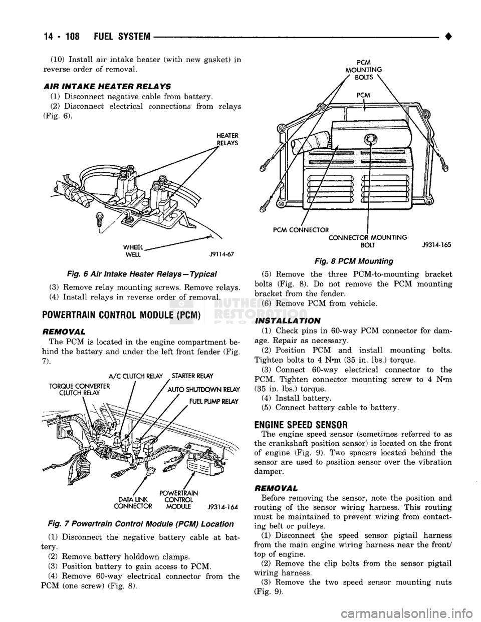
(1) Disconnect negative cable from battery.
(2) Disconnect electrical connections from relays
(Fig. 6).
HEATER
RELAYS
WHEEL..
WELL
J9114-67
Fig. 6 Air intake Heater Relays—Typical (3) Remove relay mounting screws. Remove relays.
(4) Install relays in reverse order of removal.
POWERTRAIN CONTROL MODULE
(PCI)
REMOWAL The PCM is located in the engine compartment be
hind the battery and under the left front fender (Fig.
7).
TORQUE CONVERTER
CLUTCH RELAY A/C CLUTCH RELAY STARTER RELAY
AUTO SHUTDOWN RELAY FUEL PUMP RELAY DATA LINK
CONNECTOR POWERTRAIN
CONTROL
MODULE
J9314-164
Fig. 7 Powertrain Control
Module
(PCM) Location (1) Disconnect the negative battery cable at bat
tery.
(2) Remove battery holddown clamps.
(3) Position battery to gain access to PCM,
(4) Remove 60-way electrical connector from the
PCM (one screw) (Fig. 8).
PCM
MOUNTING BOLTS
PCM CONNECTOR CONNECTOR MOUNTING
BOLT
J9314-165
Fig. 8 PCM Mounting (5) Remove the three PCM-to-mounting bracket
bolts (Fig. 8). Do not remove the PCM mounting
bracket from the fender.
(6) Remove PCM from vehicle.
INSTALLATION (1) Check pins in 60-way PCM connector for dam
age.
Repair as necessary.
(2) Position PCM and install mounting bolts.
Tighten bolts to 4 N*m (35 in. lbs.) torque.
(3) Connect 60-way electrical connector to the
PCM. Tighten connector mounting screw to 4 N#m (35 in. lbs.) torque. (4) Install battery. (5) Connect battery cable to battery.
ENGINE
SPEED SENSOR
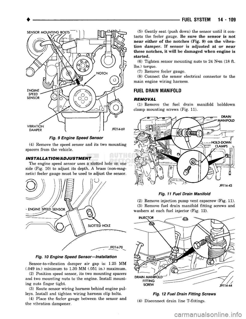
The engine speed sensor (sometimes referred to as
the crankshaft position sensor) is located on the front of engine (Fig. 9). Two spacers located behind the
sensor are used to position sensor over the vibration
damper.
REMOWAL Before removing the sensor, note the position and
routing of the sensor wiring harness. This routing must be maintained to prevent wiring from contact
ing belt or pulleys.
(1) Disconnect the speed sensor pigtail harness
from the main engine wiring harness near the front/
top of engine.
(2) Remove the clip bolts from the sensor pigtail
wiring harness. (3) Remove the two speed sensor mounting nuts
(Fig. 9).
Page 928 of 1502
SENSOR
MOUNTING BOLTS
VIBRATION
DAMPER
J9214-69
Fig.
9
Engine Speed Sensor
(4) Remove the speed sensor and its two mounting
spacers from the vehicle.
INST
ALL A
TION/ADJUSTMENT
The engine speed sensor uses a slotted hole on one
side (Fig. 10) to adjust its depth. A brass (non-mag
netic) feeler gauge must be used to adjust the sensor.
Fig.
10
Engine Speed
Sensor—Installation
Sensor-to-vibration damper air gap is: 1.25 MM
(.049 in.) minimum to 1.30 MM (.051 in.) maximum.
(2) Position speed sensor, its two mounting spacers
and two mounting nuts to the engine. Install mount
ing nuts finger tight.
(3) Route sensor wiring harness behind engine pul
leys.
Install and tighten wiring harness clip bolts. (4) Place the feeler gauge between the sensor and
the vibration dampener. (5) Gently seat (push down) the sensor until it con
tacts the feeler gauge. Be sure the sensor is not
near either of the notches (Fig. 9) on the vibra
tion damper. If sensor is adjusted at or near
these notches, it will be damaged when engine is started.
(6) Tighten sensor mounting nuts to 24 N#m (18 ft.
lbs.) torque.
(7) Remove feeler gauge.
(8) Connect the sensor electrical connector to the
main engine wiring harness.
FUEL
DRAIN
MANIFOLD
REMOVAL
(1) Remove the fuel drain manifold holddown
clamp mounting screws (Fig. 11).
DRAIN
MANIFOLD
J9114-43
Fig.
11
Fuel
Drain Manifold
(2) Remove injection pump vent capscrew (Fig. 11).
(3) Remove fuel drain manifold fitting screws and
washers at each fuel injector (Fig. 12).
INJECTOR
DRAIN
MANIFOLD
FITTING
SCREW
J9114-44
Fig.
12
Fuel
Drain
Fitting
Screws
(4) Disconnect drain line T-fittings.