1993 DODGE TRUCK sensor
[x] Cancel search: sensorPage 879 of 1502
14 - SO
FUEL
SYSTEM
•
HIGH
AND LOW
LIMITS
The powertrain control module (PCM) compares in
put signal voltages from each input device. It will es
tablish high and low limits that are programmed into it for that device. If the input voltage is not
within specifications and other diagnostic trouble code (DTC) criteria are met, a DTC will be stored in
memory. Other DTC criteria might include engine
rpm limits or input voltages from other sensors or switches. The other inputs might have to be sensed
by the PCM when it senses a high or low input volt age from the control system device in question.
ACCESSING DIAGNOSTIC TROUBLE CODES A stored diagnostic trouble code (DTC) can be dis
played by cycling the ignition key On-Off-On-Off-On
within three seconds and observing the malfunction indicator lamp. This lamp was formerly referred to
as the check engine lamp. The lamp is located on the
instrument panel.
They can also be displayed through the use of the
Diagnostic Readout Box II (DRB II scan tool). The
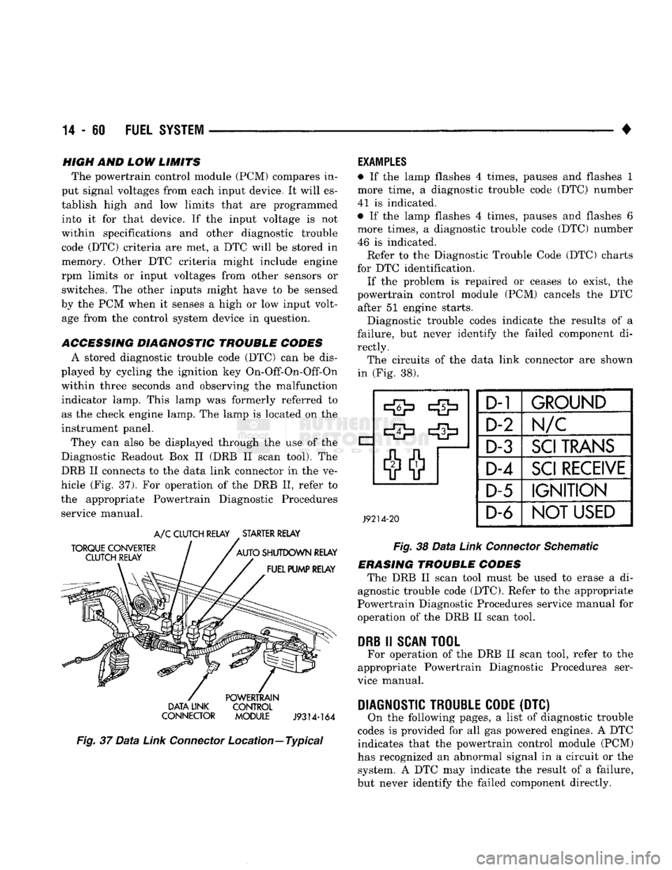
DRB II connects to the data link connector in the ve
hicle (Fig. 37). For operation of the DRB II, refer to
the appropriate Powertrain Diagnostic Procedures service manual.
TORQUE CONVERTER
CLUTCH RELAY
A/C
CLUTCH RELAY
.
STARTER RELAY
AUTO
SHUTDOWN RELAY FUEL PUMP RELAY POWERTRAIN
DATA LINK CONTROL
CONNECTOR MODULE
J9314-164
Fig.
37
Data
Link
Connector
Location—Typical
EXAMPLES
• If the lamp flashes 4 times, pauses and flashes 1
more time, a diagnostic trouble code (DTC) number
41 is indicated.
• If the lamp flashes 4 times, pauses and flashes 6
more times, a diagnostic trouble code (DTC) number
46 is indicated. Refer to the Diagnostic Trouble Code (DTC) charts
for DTC identification. If the problem is repaired or ceases to exist, the
powertrain control module (PCM) cancels the DTC after 51 engine starts.
Diagnostic trouble codes indicate the results of a
failure, but never identify the failed component di
rectly. The circuits of the data link connector are shown
in (Fig. 38).
J9214-20
D-1
GROUND
D-2 Im/c
D-3
SCI
TRANS
D-4
SCI
RECEIVE
D-5
IGNITION
D-6
NOT
USED
Fig.
38
Data
Link
Connector
Schematic
ERASING TROUBLE CODES The DRB II scan tool must be used to erase a di
agnostic trouble code (DTC). Refer to the appropriate
Powertrain Diagnostic Procedures service manual for operation of the DRB II scan tool.
DRB
II
SCAN
TOOL
For operation of the DRB II scan tool, refer to the
appropriate Powertrain Diagnostic Procedures ser
vice manual.
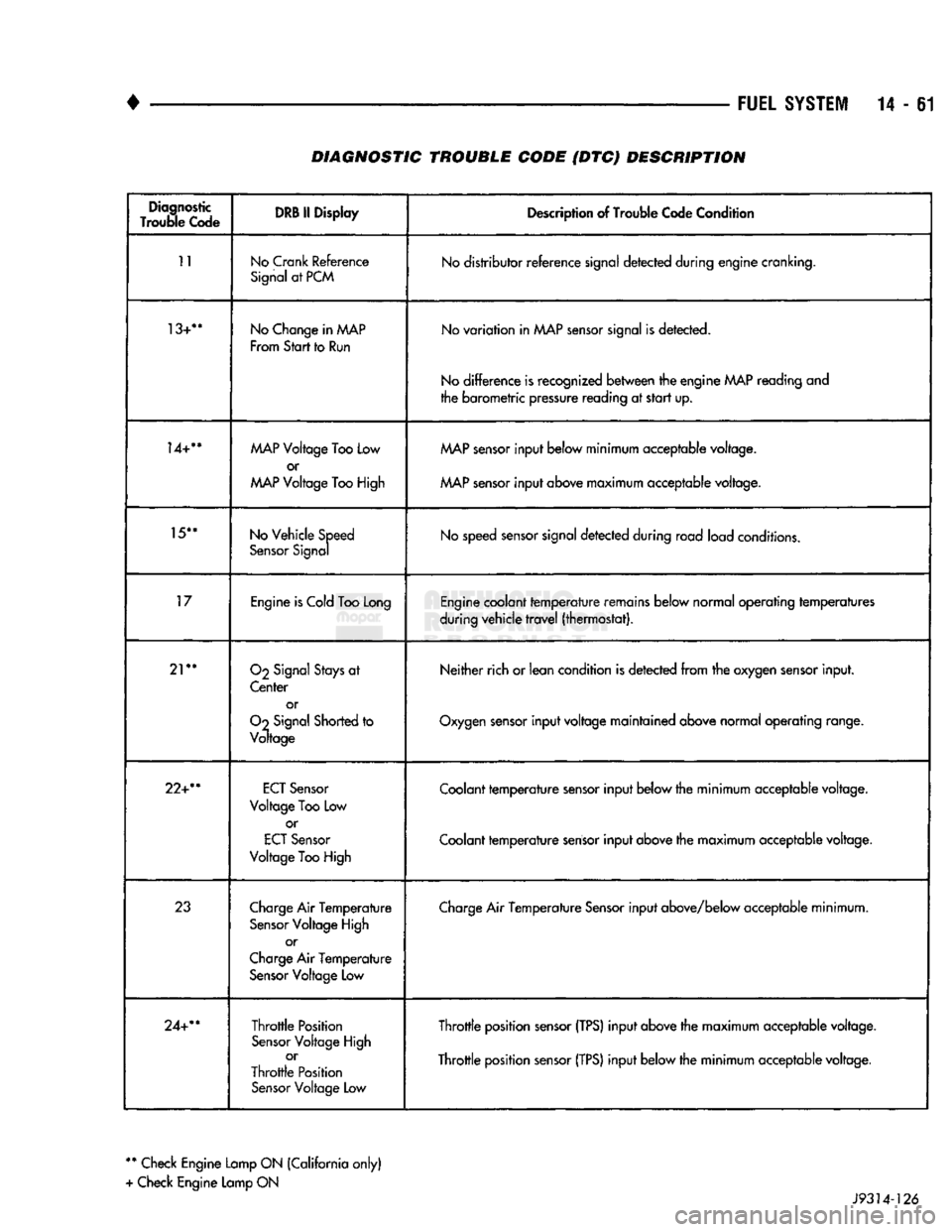
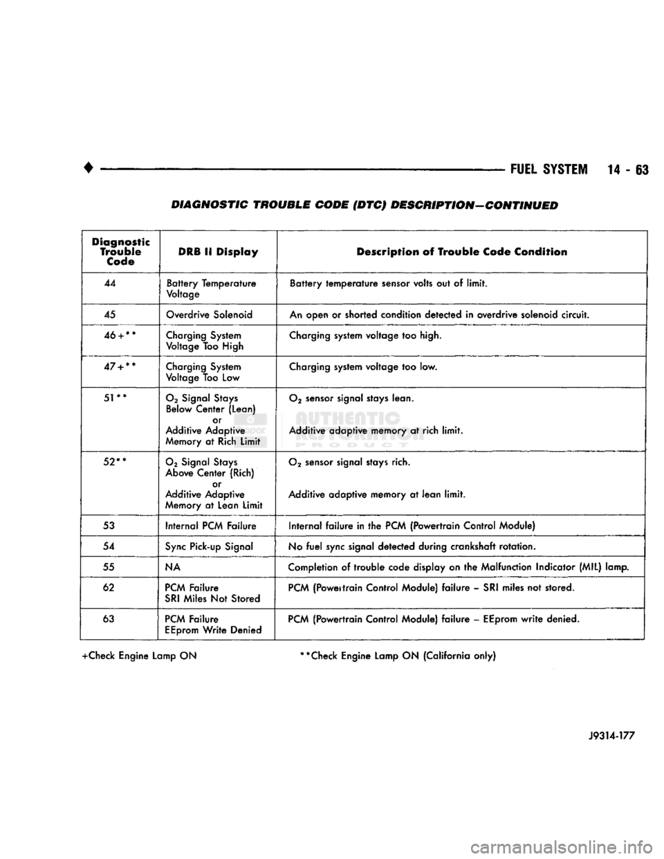
DIAGNOSTIC TROUBLE CODE
(DTC) On the following pages, a list of diagnostic trouble
codes is provided for all gas powered engines. A DTC indicates that the powertrain control module (PCM)
has recognized an abnormal signal in a circuit or the system. A DTC may indicate the result of a failure,
but never identify the failed component directly.
Page 880 of 1502
•
FUEL
SYSTEM
14-61 DIAGNOSTIC TROUBLE CODE {DTC) DESCRIPTION
Diagnostic
Trouble
Code DRB II
Display
Description of Trouble Code Condition
11
No
Crank
Reference
Signal at PCM No distributor reference signal detected during engine cranking.
13+**
No Change in
AAAP
From
Start
to Run No variation in MAP sensor signal is detected.
No difference is recognized between the engine
MAP
reading and
the barometric pressure reading at start up.
14+**
MAP
Voltage Too Low
or
MAP
Voltage Too High
MAP
sensor input below minimum acceptable voltage.
MAP sensor input above maximum acceptable voltage.
15**
No Vehicle Speed
Sensor Signal No speed sensor signal detected during road load conditions.
17
Engine is Cold Too Long Engine coolant temperature remains below normal operating temperatures
during vehicle travel (thermostat).
21**
O2
Signal Stays at
Center or
Oo
Signal Shorted to
Voltage Neither rich or lean condition
is
detected from the oxygen sensor input.
Oxygen sensor input voltage maintained above normal operating range.
22+**
ECT
Sensor
Voltage
Too
Low or
ECT
Sensor
Voltage
Too
High Coolant temperature sensor input below the minimum acceptable voltage.
Coolant temperature sensor input above the maximum acceptable voltage.
23
Charge Air Temperature
Sensor Voltage High or
Charge Air Temperature Sensor Voltage Low Charge Air Temperature Sensor input above/below acceptable minimum.
24+**
Throttle Position
Sensor Voltage High or
Throttle Position Sensor Voltage
Low
Throttle position sensor
(TPS)
input above the maximum acceptable voltage.
Throttle position sensor
(TPS)
input below the minimum acceptable voltage.
**
Check Engine Lamp ON (California only)
+ Check Engine Lamp ON J9314-126
Page 882 of 1502
•
FUEL
SYSTEM
14 - 63 DIAGNOSTIC TROUBLE CODE (DTC) DESCRIPTION-CONTINUED
Diagnostic
Trouble
Code
DRB
11
Display
Description
of
Trouble
Code
Condition
44
Battery Temperature
Voltage
Battery temperature
sensor
volts
out of
limit.
45
Overdrive
Solenoid
An
open
or
shorted condition detected
in
overdrive solenoid
circuit.
46
+
**
Charging
System
Voltage
Too High
Charging
system voltage
too
high.
47
+
**
Charging
System
Voltage
Too
Low
Charging
system voltage
too low.
51**
02
Signal
Stays
Below
Center (Lean) or
Additive Adaptive
Memory
at
Rich
Limit
02
sensor
signal
stays
lean.
Additive adaptive memory
at rich
limit.
52**
02
Signal
Stays
Above
Center (Rich) or
Additive Adaptive
Memory
at
Lean
Limit
02
sensor
signal
stays
rich.
Additive adaptive memory
at
lean
limit.
53
Internal
PCM
Failure Internal
failure in the
PCM
{Powertrain Control Module)
54
Sync
Pick-up
Signal
No
fuel
sync
signal detected during crankshaft rotation.
55
NA
Completion
of trouble
code display
on the
Malfunction Indicator (MIL) lamp.
62
PCM
Failure
SRI
Miles
Not
Stored
PCM
(Powertrain Control Module)
failure -
SRI
miles
not
stored.
63
PCM
Failure
EEprom
Write Denied
PCM
(Powertrain Control Module)
failure -
EEprom
write
denied.
+Check Engine Lamp ON **Check Engine Lamp ON (California only)
J9314-177
Page 883 of 1502
MULTI-PORT
FUEL
INJECTION
(MPI)-COMPONENT
REMOVAL/INSTALLATION
—EXCEPT DIESEL
INDEX
page
Accelerator Pedal
and Throttle
Cable
. 64
Air Conditioning (A/C) Clutch Relay
64
Air
Filter/Filter
Housing
64
Automatic Shut Down (ASD) Relay
. 64
Brake
Switch
64
Camshaft
Position
Sensor
..................
64
Charge
Air
Temperature
Sensor
64
Crankshaft Position
Sensor
64
Engine
Coolant Temperature
Sensor
65
EVAP
Canister Purge Solenoid
65
Fuel
Filter
65
Fuel Filter/Fuel Pressure Regulator—5.9L Engine
. 65
Fuel Injector(S)
67
Fuel Pressure Regulator
67
Fuel Pump Module
68
Fuel Pump Relay
68
ACCELERATOR
PEDAL
AND THROTTLE
CABLE
Refer
to
the
Accelerator Pedal
and
Throttle Cable
section
of
this group
for
removal/installation proce
dures.
AIR
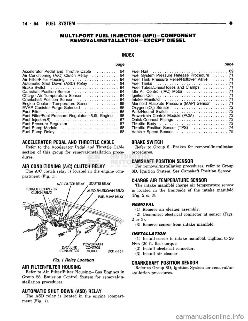
CONDITIONING (A/C) CLUTCH RELAY The A/C clutch relay
is
located
in
the
engine com
partment (Fig.
1).
A/C CLUTCH RELAY STARTER RELAY
DATA LINK CONTROL
CONNECTOR MODULE
J9314-164
Fig.
1 Relay Location
AIR
FILTER/FILTER
HOUSING
Refer
to
Air Filter/Filter Housing—Gas Engines
in
Group
25,
Emission Control System
for
removal/in
stallation procedures.
AUTOMATIC SHUT DOWN (ASD) RELAY The ASD relay
is
located
in
the
engine compart
ment (Fig.
1).
page
Fuel Rail
69
Fuel System Pressure Release Procedure
......
71
Fuel Tank Pressure Relief/Rollover Valve
71
Fuel Tanks
71
Fuel
Tubes/Lines/Hoses
and
Clamps
71
Idle
Air
Control (IAC) Motor
71
Ignition Coil
71
Intake Manifold
71
Manifold Absolute Pressure (MAP)
Sensor
71
Oxygen
(02)
Sensor
72
Park/Neutral Switch
. 73
Powertrain Control Module (PCM)
73
Quick-Connect
Fittings
73
Throttle
Body
73
Throttle
Position
Sensor
(TPS)
......
74
Vehicle
Speed
Sensor
75
BRAKE
SWITCH
Refer
to
Group
5,
Brakes
for
removal/installation
procedures.
CAMSHAFT
POSITION
SENSOR
For removal/installation procedures, refer
to
Group
8D,
Ignition System. See Camshaft Position Sensor.
CHARGE
AIR
TEMPERATURE SENSOR
The intake manifold charge
air
temperature sensor
is located
in the
front/side
of
the
intake manifold (Fig.
2
or
3).
REMOVAL
(1) Remove
air
cleaner assembly.
(2) Disconnect electrical connector
at
sensor (Figs.
2
or
3). (3) Remove sensor from intake manifold.
INSTALLATION
(1) Install sensor
to
intake manifold. Tighten
to 28
Nnn (20
ft.
lbs.) torque.
(2) Install electrical connector.
(3) Install
air
cleaner.
CRANKSHAFT
POSITION
SENSOR
Refer
to
Group 8D, Ignition System
for
removal/in
stallation procedures.
Page 884 of 1502
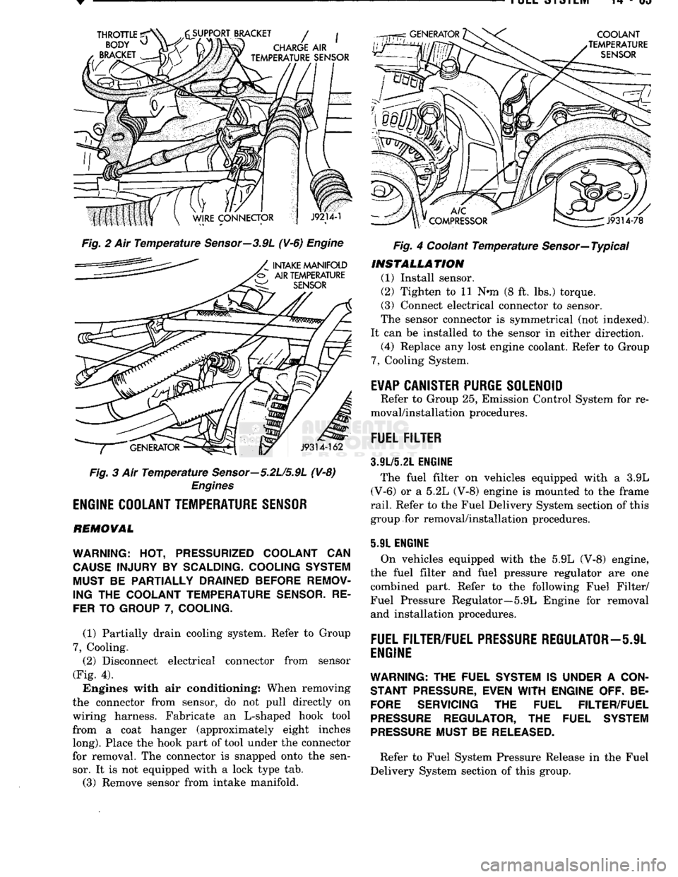
Fig. 2 Ait Temperature Sensor—3.9L (¥-6) Engine
Fig. 3 Air Temperature Sensor—5.2U5.9L (V-8)
Engines
ENGINE
COOLANT
TEMPERATURE
SENSOR
REMOVAL
WARNING:
HOT,
PRESSURIZED COOLANT
CAN
CAUSE
INJURY
BY
SCALDING- COOLING SYSTEM MUST
BE
PARTIALLY DRAINED BEFORE REMOV
ING
THE
COOLANT TEMPERATURE
SENSOR.
RE
FER
TO
GROUP
7,
COOLING.
(1) Partially drain cooling system. Refer to Group
7,
Cooling. (2) Disconnect electrical connector from sensor
(Fig. 4).
Engines with air conditioning: When removing
the connector from sensor, do not pull directly on
wiring harness. Fabricate an L-shaped hook tool from a coat hanger (approximately eight inches
long).
Place the hook part of tool under the connector
for removal. The connector is snapped onto the sen sor. It is not equipped with a lock type tab.
(3) Remove sensor from intake manifold. Fig. 4 Coolant Temperature Sensor—Typical
INSTALLATION
(1) Install sensor.
(2) Tighten to 11 Nnn (8 ft. lbs.) torque.
(3) Connect electrical connector to sensor.
The sensor connector is symmetrical (not indexed).
It can be installed to the sensor in either direction. (4) Replace any lost engine coolant. Refer to Group
7,
Cooling System.
E¥AP
CANISTER
PURGE
SOLENOID
Refer to Group 25, Emission Control System for re
moval/installation procedures.
FUEL
FILTER
3.9L/5.21.
ENGINE
The fuel filter on vehicles equipped with a 3.9L
(V-6) or a 5.2L (V-8) engine is mounted to the frame
rail.
Refer to the Fuel Delivery System section of this
group for removal/installation procedures.
5.91 ENGINE
On vehicles equipped with the 5.9L (V-8) engine,
the fuel filter and fuel pressure regulator are one combined part. Refer to the following Fuel Filter/
Fuel Pressure Regulator—5.9L Engine for removal and installation procedures.
FUEL
FILTER/FUEL
PRESSURE
REGULATOR—5JL
ENGINE
WARNING:
THE FUEL SYSTEM IS UNDER A
CON
STANT
PRESSURE,
EVEN
WITH
ENGINE OFF. BE
FORE
SERVICING THE FUEL FILTER/FUEL
PRESSURE
REGULATOR, THE FUEL SYSTEM
PRESSURE
MUST BE
RELEASED.
Refer to Fuel System Pressure Release in the Fuel
Delivery System section of this group.
Page 888 of 1502
FUEL
RAIL
WARNING:
THE
FUEL SYSTEM
IS
UNDER
A
CON STANT PRESSURE (EVEN
WITH
THE
ENGINE
TURNED
OFF).
BEFORE SERVICING
THE
FUEL RAIL ASSEMBLY,
THE
FUEL SYSTEM PRESSURE
MUST
BE
RELEASED.
To release fuel pressure, refer to the Fuel Delivery
System section of this group. See Fuel System Pres
sure Release.
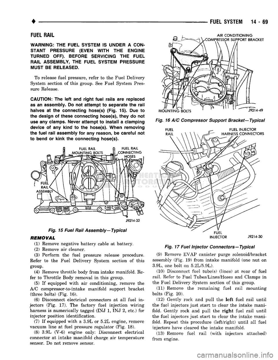
CAUTION:
The left and
right
fuel
rails
are
replaced
as
an
assembly.
Do not
attempt
to
separate
the
rail
halves
at the
connecting hose(s)
(Fig. 15). Due to
the design
of
these connecting hose(s),
they
do not
use
any
clamps. Never
attempt
to
install
a
clamping
device
of any
kind
to the
hose(s).
When
removing
the
fuel
rail
assembly
for any
reason,
be
careful
not
to bend
or
kink
the
connecting hose(s). FUEL RAIL
CONNECTING
HOSES
AIR
CONDITIONING
/COMPRESSOR
SUPPORT BRACKET
MOUNTING
BOLTS
' "
J9214-49
Fig.
16 A/C
Compressor
Support
Bracket—
Typical
FUEL RAIL FUEL INJECTOR
HARNESS
CONNECTORS
J9214-32
Fig.
15
Fuel
Rail
Assembly—
Typical
REMOVAL
(1) Remove negative battery cable at battery.
(2) Remove air cleaner.
(3) Perform the fuel pressure release procedure.
Refer to the Fuel Delivery System section of this group.
(4) Remove throttle body from intake manifold. Re
fer to Throttle Body removal in this group.
(5) If equipped with air conditioning, remove the
A/C compressor-to-intake manifold support bracket (three bolts) (Fig. 16). (6) Disconnect electrical connectors at all fuel in
jectors (Fig. 17). The factory fuel injection wiring harness is numerically tagged (INJ 1, INJ 2, etc.) for injector position identification. (7) If equipped with a 3.9L or 5.2L engine, remove
vacuum line at fuel pressure regulator (Fig. 18). (8) 3.9L (V-6) engine only: Disconnect electrical
connector at intake manifold charge air temperature sensor. Do not remove sensor. '
FUEL
INJECTOR
J9214-30
Fig.
17
Fuel
Injector Connectors—Typical
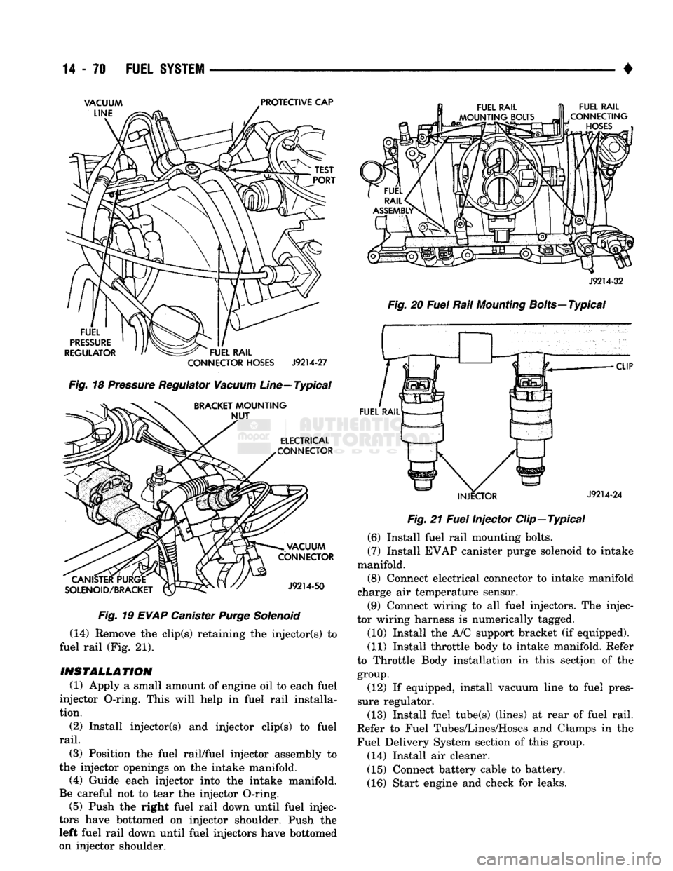
(9) Remove EVAP canister purge solenoid/bracket
assembly (Fig. 19) from intake manifold (one nut on
3.9L, one bolt on 5.2L/5.9L).
(10) Disconnect fuel tube(s) (lines) at rear of fuel
rail.
Refer to Fuel Tubes/Lines/Hoses and Clamps in
the Fuel Delivery System section of this group.
(11) Remove the remaining fuel rail mounting
bolts (Fig. 20).
(12) Gently rock and pull the left fuel rail until
the fuel injectors just start to clear the intake mani
fold. Gently rock and pull the right fuel rail until
the fuel injectors just start to clear the intake mani fold. Repeat this procedure (left/right) until all fuel injectors have cleared the intake manifold.
(13) Remove fuel rail (with injectors attached)
from engine.
Page 889 of 1502
14
- 70
FUEL
SYSTEM
•
CANISTER PURGE
SOLENOID/BRACKET VACUUM
CONNECTOR
J9214-50
Fig.
19
EVAP
Canister
Purge
Solenoid
(14) Remove the clip(s) retaining the injector(s) to
fuel rail (Fig. 21).
INSTALLATION
(1) Apply a small amount of engine oil to each fuel
injector O-ring. This will help in fuel rail installa
tion.
(2) Install injector(s) and injector clip(s) to fuel
rail.
(3) Position the fuel rail/fuel injector assembly to
the injector openings on the intake manifold.
(4) Guide each injector into the intake manifold.
Be careful not to tear the injector O-ring. (5) Push the right fuel rail down until fuel injec
tors have bottomed on injector shoulder. Push the
left fuel rail down until fuel injectors have bottomed
on injector shoulder.
INJECTOR
J9214-24
Fig.
21
Fuel
Injector Clip—Typical
(6) Install fuel rail mounting bolts.
(7) Install EVAP canister purge solenoid to intake
manifold. (8) Connect electrical connector to intake manifold
charge air temperature sensor.
(9) Connect wiring to all fuel injectors. The injec
tor wiring harness is numerically tagged.
(10) Install the A/C support bracket (if equipped).
(11) Install throttle body to intake manifold. Refer
to Throttle Body installation in this section of the
group.
(12) If equipped, install vacuum line to fuel pres
sure regulator.
(13) Install fuel tube(s) (lines) at rear of fuel rail.
Refer to Fuel Tubes/Lines/Hoses and Clamps in the
Fuel Delivery System section of this group.
(14) Install air cleaner. (15) Connect battery cable to battery.
(16) Start engine and check for leaks.
Page 890 of 1502
•
FUEL SYSTEM
14-71
FUEL SYSTEM PRESSURE RELEASE PROCEDURE
WARNING:
THE
FUEL
SYSTEM
IS
UNDER
A
CON
STANT
PRESSURE
(EVEN
WITH
THE
ENGINE
TURNED
OFF).
BEFORE
SERVICING
THE
FUEL
PUMP,
FUEL
LINES
(TUBES),
FUEL
FILTER,
OR
FUEL
INJECTOR(S),
THE
FUEL
SYSTEM
PRESSURE
MUST
BE
RELEASED.
To release fuel pressure, refer to the Fuel Delivery
System section of this group. See Fuel System Pres
sure Release Procedure.
FUEL TANKS
Refer to the Fuel Tank section of this group for re
moval/installation procedures.
FUEL TANK
PRESSURE
RELIEF/ROLLOVER VALVE
Refer to the Fuel Tank section of this group for re
moval/installation procedures.
FUEL
TUBES/LINES/HOSES
AND CLAMPS
Refer to Fuel Tubes/Lines/Hoses and Clamps in the
Fuel Delivery System section of this group for remov al/installation procedures. Also refer to Quick-Connect Fittings in the Fuel
Delivery System section of this group for removal/in
stallation procedures.
IDLE
AIR
CONTROL
(IAC)
MOTOR
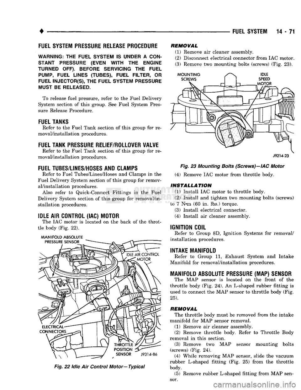
The IAC motor is located on the back of the throt
tle body (Fig. 22).
MANIFOLD ABSOLUTE
Fig.
22
idle
Air Control Motor—Typical
REMOVAL
(1) Remove air cleaner assembly.
(2) Disconnect electrical connector from IAC motor.
(3) Remove two mounting bolts (screws) (Fig. 23).
J9214-23
Fig.
23
Mounting
Bolts
(Screws)—IAC
Motor
(4) Remove IAC motor from throttle body.
INSTALLATION
(1) Install IAC motor to throttle body.
(2) Install and tighten two mounting bolts (screws)
to 7 N»m (60 in. lbs.) torque.
(3) Install electrical connector.
(4) Install air cleaner assembly.
IGNITION COIL
Refer to Group 8D, Ignition Systems for removal/
installation procedures.
INTAKE MANIFOLD
Refer to Group 11, Exhaust System and Intake
Manifold for removal/installation procedures.
MANIFOLD ABSOLUTE
PRESSURE
(MAP)
SENSOR
The MAP sensor is located on the front of the
throttle body (Fig. 24). An L-shaped rubber fitting is
used to connect the MAP sensor to throttle body (Fig.
25).
REMOVAL
The throttle body must be removed from the intake
manifold for MAP sensor removal.
(1) Remove air cleaner assembly.
(2) Remove throttle body. Refer to Throttle Body
removal in this section.
(3) Remove two MAP sensor mounting bolts
(screws) (Fig. 24). (4) While removing MAP sensor, slide the vacuum
rubber L-shaped fitting (Fig. 25) from the throttle
body.
(5) Remove rubber L-shaped fitting from MAP sen
sor.