1993 DODGE TRUCK sensor
[x] Cancel search: sensorPage 21 of 1502
0 - 2
LUBRICATION
AND
MAINTENANCE
• Commercial service
When a vehicle is continuously subjected to severe
driving conditions, lubricate:
• Body components
• All the driveline coupling joints
• Steering linkage More often than normal driving conditions
DUSTY
AREAS
With this type of severe driving condition, special
care should be given to the:
• Engine air cleaner filter
• PCV filter
• Crankcase ventilation system
• Brake booster control valve air filter. Verify that the filters and the associated compo
nents are clean. Also verify that they are functioning
effectively. This will minimize the amount of abra sive particles that enter the engine.
OFF-ROAD
(4WD)
OPERATION
After off-road (4WD) operation, inspect the under
side of the vehicle. Inspect the:
• Tires
• Body structure
• Steering components
• Suspension components • Exhaust system
• Threaded fasteners
HARSH
SURFACE ENVIRONMENTS
After extended operation in harsh environments,
the brake drums, brake linings, and rear wheel bear ings should be inspected and cleaned. This will pre
vent wear and erratic brake action.
ROUTINE MAINTENANCE
The following routine maintenance is recommended
on a monthly basis: TIRES—Inspect the tires for unusual wear/damage.
Determine if the inflation pressure is adequate for
the vehicle load. BATTERY—Inspect and clean the terminals.
Tighten the terminals if necessary. FLUIDS—Determine if the component fluid levels
are acceptable. Add fluid, if necessary. LIGHTS/ELECTRICAL—Test all the electrical sys
tems in the vehicle for proper operation. It is also recommended that the engine oil and the
washer fluid level be determined at each fuel fill-up.
VEHICLE
NOISE CONTROL
Vehicles with a GVWR of 4 535 kg (10,000 lbs), or
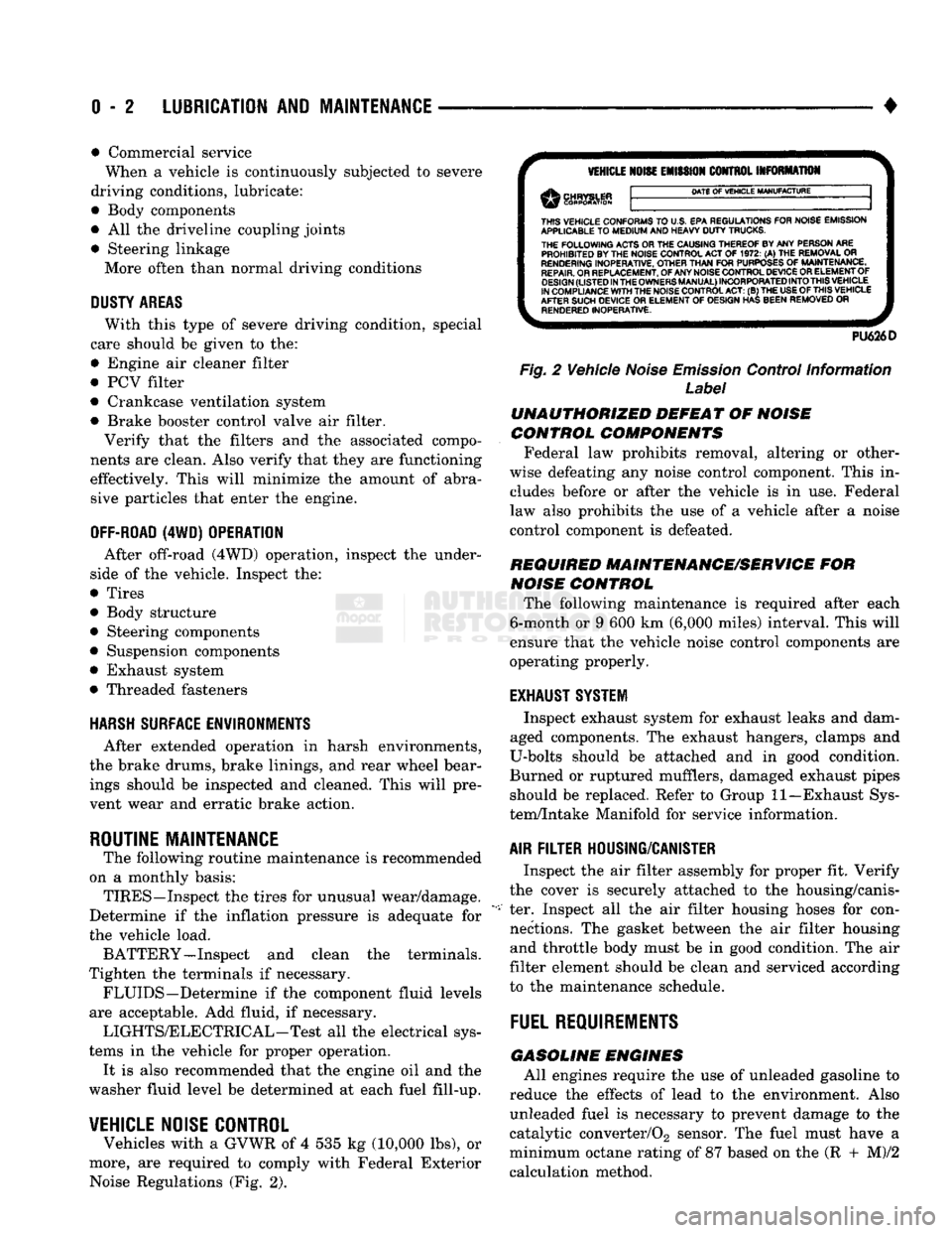
more, are required to comply with Federal Exterior Noise Regulations (Fig. 2).
VEHICLE
NOISE
EMISSION
CONTROL INFORMATION
DATE
OF
VEHICLE
MANUFACTURE
THIS
VEHICLE CONFORMS
TO
U.S. EPA REGULATIONS FOR NOISE EMISSION
APPLICABLE
TO
MEDIUM
AND HEAVY
DUTY
TRUCKS. THE
FOLLOWING
ACTS OR THE CAUSING THEREOF BY ANY PERSON ARE PROHIBITED BY THE NOISE CONTROL ACT
OF 1972. (A) THE
REMOVAL
OR
RENDERING
INOPERATIVE, OTHER
THAN
FOR
PURPOSES
OF
MAINTENANCE,
REPAIR.
OR REPLACEMENT, OF ANY NOISE CONTROL DEVICE OR ELEMENT OF
DESIGN
(LISTED
IN
THE
OWNERS
MANUAL)
INCORPORATED
INTO
THIS
VEHICLE
IN COMPLIANCE
WITH
THE NOISE CONTROL
ACT:
(B) THE
USE
OF
THIS
VEHICLE
AFTER SUCH DEVICE
OR
ELEMENT
OF
DESIGN HAS BEEN REMOVED
OR
RENDERED
INOPERATIVE.
PU626D
Fig.
2 Vehicle
Noise
Emission
Control Information
Label
UNAUTHORIZED
DEFEAT
OF
NOISE
CONTROL COMPONENTS
Federal law prohibits removal, altering or other
wise defeating any noise control component. This in
cludes before or after the vehicle is in use. Federal
law also prohibits the use of a vehicle after a noise
control component is defeated.
REQUIRED MAINTENANCE/SERVICE
FOR
NOISE
CONTROL
The following maintenance is required after each
6-month or 9 600 km (6,000 miles) interval. This will
ensure that the vehicle noise control components are
operating properly.
EXHAUST SYSTEM
Inspect exhaust system for exhaust leaks and dam
aged components. The exhaust hangers, clamps and
U-bolts should be attached and in good condition.
Burned or ruptured mufflers, damaged exhaust pipes should be replaced. Refer to Group 11—Exhaust Sys
tem/Intake Manifold for service information.
AIR
FILTER
HOUSING/CANISTER
Inspect the air filter assembly for proper fit. Verify
the cover is securely attached to the housing/canis
ter. Inspect all the air filter housing hoses for con nections. The gasket between the air filter housing and throttle body must be in good condition. The air
filter element should be clean and serviced according
to the maintenance schedule.
FUEL
REQUIREMENTS
GASOLINE
ENGINES
All engines require the use of unleaded gasoline to
reduce the effects of lead to the environment. Also unleaded fuel is necessary to prevent damage to the
catalytic converter/02 sensor. The fuel must have a
minimum octane rating of 87 based on the (R + M)/2
calculation method.
Page 25 of 1502

0 - 6
LUBRICATION
AND
MAINTENANCE
GASOLINE ENGINE MAINTENANCE SCHEDULE
HEAVY
DUTY
CYCLE
Inspection and service is also necessary anytime
a
malfunction is observed or suspected.
When both
time
and mileage
are
Miles (Thousand)
shewn,
follow
the
interval
which occurs first. Kilometers (Thousand) 6
12 18 24
30 36 42 48 54
60 66 72
78
82V2
84 90
96
102 108
When both
time
and mileage
are
Miles (Thousand)
shewn,
follow
the
interval
which occurs first. Kilometers (Thousand) 9.6 19 29
38 48 58 67 77
85 96 106 116
125 132
135
145
154 164
174
Coolant
Condition, Coolant
Hoses/Clamps
X
X X X
X X X X
X X X X
X X X
X X X
Exhaust
System
—
Check
X X X X X X X X X X X
X X X X X
X X
Oil
—
Change
(6
Months)
X X X X X X X
X X
X
X
X
X X X
X X
X
Oil
Filter
—
Change (2nd
Oil
Change)
X X X X
X X
X X
X
Drive Belt Tension
—
Inspect
&
Adjust
X' X
X1
X X' X
Drive Belts (V-Type)
—
Replace
X
Air
Filter/Air
Pump
Air
Filter
—
Replace
X X X
X
Crankcase
Inlet
Air
Filter
(6 &
8
Cyl.
Eng.
Only)
—
Clean
X X
X X
Spark
Plug
—
Replace
X X X
Fuel
Filter
—
Replace as necessary
Coolant
—
Flush/Replace
(36
months)
& 24
months/48
000 km
(30,000
miles)
thereafter
X
EGR
Valve
&
Tube
—
Replace X2
EGR
Tube
—
Clean Passengers
X2
PCV
Valve
—
Replace X2
Vacuum
Emission
Components
—
Replace
X
Ignition Timing
—
Adjust
to
Specs,
as necessary X
Ignition Cables, Distributor Cap
&
Rotor
—
Replace
X
Manifold Heat Control Valve
—
Lubricate
X
Battery
—
Replace X
Oxygen
Sensor
—
Replace
X2
1 For California vehicles, this maintenance is recommended
by
Chrysler Motors
to the
owner but, is not
required
to
maintain the
warranty
on the
air
pump drive
belt.
2 Requires
Emission
Maintenance Reminder Light.
If
so equipped, these parts
are to be
replaced
at the
indicated mileage,
or
when the
emissions
maintenance reminded light remains on continuously
with
the key in the
"on" position, whichever occurs first.
J9100-20
DIESEL
ENGINE
MAINTENANCE
SCHEDULE
HEAVY
DUTY
CYCLE
Inspection
and
service
is
also
necessary
any
time
a
malfunction
is
observed
or
suspected.
Iff both
time
and distance Miles (Thousand)
are listed, use the
interval
that
ends
first. Kilometers (Thousand) 6
12
18 24
30 36 42
4S
54
60 66
72 78
84 90 96
102 108
Iff both
time
and distance Miles (Thousand)
are listed, use the
interval
that
ends
first. Kilometers (Thousand) 9,6 19
29
38 48 58 67
77
85 96 106
116 125 135 145 154
164 174
Coolant
Condition, Coolant
Hoses/Clamps
(12 months)
Coolant
Flush/Replace (36 months) & 24 months/
48 000 km
(30,000
miles)
thereafter
O
Oil—Change
(6 months)
X X X
X X X
X X X X X
X X X X X X
X
Oil Filter—Replace (Every Oil Change)
X X X
X X X
X X
X X X
X
X X X X
X X
Drive Belts—Replace
As
Necessary
X X
X X X X
Air Filter—Replace
X X
X X
Air Filter—Clean (California Only) e
®
• •
Air
Filter
Canister—Clean
o o o
o
Fuel Filter—Service When Necessary
Injection
Pump
Timing & Engine Idle Speed—
Check
& Adjust
©
• 9 • • •
Underhood Rubber/Plastic Components—Inspect/Replace • • • • •
X
— All vehicles
O
— All
vehicles
except
California.
Recommended
for
California.
•
— California only.
Recommended
for all vehicles.
Page 33 of 1502

0 - 14
LUBRICATION
AND
MAINTENANCE
•
ENGINE
MAINTENANCE
INDEX
page
Air
Injection
Systems/Air Pump
. 17
Air-Conditioner
Compressor
21
Battery
19
Cooling System
15
Crankcase
Ventilation
System
17
Diesel Engine
Air Filter
Canister
17
Drive Belts
20
Engine
Air
Cleaner
Filter
Element
16
Engine Break-In
14
Engine
Oil 14
Engine
Oil
Change
and Filter
Replacement
15
Exhaust Gas
Recirculation
(EGR) System
...... 19
page
Exhaust
Manifold
Heat
Control
Valve
. 17
Exhaust System
, 21
Fuel System
18
Hoses
and
Fittings
16
Ignition
Cables,
Distributor
Cap and
Rotor
...... 19
Ignition
Timing
. 19
Oxygen
(02)
Sensor
19
Rubber/Plastic Components
20
Spark Plugs
. 19
Throttle
Control
Linkage
18
Vacuum Operated, Emission
Control
Components
19
ENGINE BREAK-IN
After first starting a new engine, allow it to idle
for 15 seconds before shifting into a drive gear. Also:
• Drive the vehicle at varying speeds less than 88
km/h (55 mph) for the first 480 km (300 miles).
• Avoid fast acceleration and sudden stops.
• Do not drive at full-throttle for extended periods of
time
• Do not drive at constant speeds
• Do not idle the engine excessively A special break-in engine oil is not required. The
original engine oil installed is a high quality lubri
cant. New engines tend to consume more fuel and oil un
til after the break-in period has ended.
ENGINE
OIL SPECIFICATIONS
API SERWICE
GRADE
Use an engine oil that conforms to API Service
Grade S5 SG/CD or SG/CE. MOPAR®provides engine
oils that conform to all of these service grades.
SULFATED ASH—DIESEL ENGINES
Oils that contain an excessive amount of sulfated
ash can cause deposits to develop on Diesel engine
valves. These deposits can result in valve wear.
SAE
WISC0SITY
An SAE viscosity grade is used to specify the vis
cosity of engine oil. SAE 30 specifies a single viscos
ity engine oil.
Engine oils also have multiple viscosities. 10W-30
<
5W-30
1
1 1
F
-20 0 10 20 32 60 80 100
C
-29 -18 -12 -7 0 16 27 38
ANTICIPATED
TEMPERATURE RANGE BEFORE
NEXT
OIL
CHANGE
J9000-39
Fig.
1 Temperature/Engine Oil Viscosity—Gasoline
Engines
-12°C
-18°C 10°F
0°F- 15W-40
-23°c(^-10eF
I
10W-30
WITH
WITHOUT
BLOCK HEATER
BLOCK
SYNTHETIC
OIL
HEATER
10W-30 5W-30
J9100-29
Fig.
2 Temperature/Engine Oil Viscosity—Diesel
Engines
ENERGY
G0NSERWING
OIL
An Energy Conserving type oil is recommended for
gasoline engines. They are designated as either EN
ERGY CONSERVING or ENERGY CONSERVING
II.
OIL
LEVEL
INDICATOR (DIPSTICK)
GASOLINE ENGINES
The engine oil indicator is located at the right
front of the engine.
Page 38 of 1502

•
LUBRICATION
AND
MAINTENANCE
0 - 19 ETBE— This fuel is a mixture of unleaded gasoline
and up to 17 percent ETBE (Ethyl Tertiary Butyl
Ether).
Unleaded gasoline blended with ETBE is ac ceptable.
METHANOL—Do not use unleaded gasoline
blended with methanol. The use of this type of alco hol can result in engine performance and damage to
critical components. Engine problems that result
from the use of methanol possibly will not be covered by the new vehicle warranty.
Certain brands of unleaded gasoline contain a per
centage of unidentified alcohol. These types of un
leaded gasoline are not recommended.
ADDITIVES MIXED
WITH
GASOLINE
Use of fuel system cleaning additives should be
avoided. Many of these solutions could contain highly
active solvents. This type of solvent can be harmful
to the gasket and diaphragm material within the fuel system.
DIESEL
ENGINE FUEL REQUIREMENTS
All Diesel engines normally can use number 2D
Diesel fuel for most year-round operations. A fuel
conforming to ASTM Specification D-975 is recom
mended. For extreme cold-weather operation (below
-18°C/0°F), or for prolonged cold-climate operation ei
ther:
• Use No. ID fuel, or
• Add an equal quantity of kerosene to No. 2D fuel (a 50/50 mixture).
Both methods provide protection against fuel gel
ling and waxing.
Diesel fuel seldom is without water contamination.
To help prevent fuel system malfunctions, drain all accumulated water from the separators periodically.
VACUUM OPERATED,
EMISSION
CONTROL
COMPONENTS
MAINTENANCE SCHEDULE
The following emission controls should be replaced
at the interval specified in the maintenance sched
ule:
• Bi-level purge check valves
• Delay valves
• Heated air temperature sensor (HATS)
• Air cleaner vacuum motors
EXHAUST
GAS RECIRCULATION (EGR)
SYSTEM
MAINTENANCE SCHEDULE
Replace the EGR valve and tube, and clean the
passages at the interval specified in maintenance schedule. If necessary, refer to Group 25—Emission
Control Systems for additional information.
OXYGEN
(02)
SENSOR
MAINTENANCE SCHEDULE
Replace the 02 sensor at the interval specified in
maintenance schedule.
IGNITION
CABLES,
DISTRIBUTOR CAP AND
ROTOR
MAINTENANCE SCHEDULE
Replace the ignition cables, distributor cap, and ro
tor at the interval specified in maintenance schedule.
Inspect the distributor for excessive wear and re
place, as necessary. Refer to Group 8D—Ignition Sys
tems for additional information.
IGNITION TIMING
MAINTENANCE SCHEDULE
Test and adjust, if necessary, the ignition timing at
the interval specified in maintenance schedule. Refer
to the specifications listed on the engine Emission Control Information label. Refer to Group 8D—Igni
tion Systems and to Group 25—Emission Control Systems for additional service information.
SPARK
PLUGS MAINTENANCE SCHEDULE
Replace the spark plugs at the interval specified in
maintenance schedule. Refer to the Spark Plugs
chart below and to Group 8D—Ignition Systems for additional service information.
SPARK
PLUGS
ENGINE
SPARK
PLUG
SPARK
PLUG
GAP
TORQUE
3.9L
5.2L
5.9L
RN12YC
RN12YC
RN12YC
0.9 mm
(0.035
in.)
0.9 mm
(0.035
in.)
0.9 mm
(0.035
in.) 41 N*m (30 ft. lb.)
41 NVn (30 ft. lb.)
41 N*m (30 ft. lb.)
J9100-17
BATTERY
MAINTENANCE SCHEDULE
Replace battery at interval specified in mainte
nance schedule.
Page 130 of 1502
•
REAR
SUSPENSION
AND
AXLE
3 - 1
CONTENTS
page
8
3/8 and 9 1/4
AXLE
11
GENERAL
INFORMATION
1
MODEL
60 and 70
AXLES
29
POWER-LOK DIFFERENTIAL
55
REAR
SUSPENSION—2WD
and
4WD VEHICLES
3
page
SERVICE
DIAGNOSIS
6
SPECIFICATIONS
27
SURE-GRIP
DIFFERENTIAL SERVICE
28
TORQUE SPECIFICATIONS
59
TRAC-LOK DIFFERENTIAL
51
GENERAL INFORMATION
SUSPENSION
Ram Truck rear suspensions
are
comprised
of;
• Drive axle
• Leaf springs
• Dual-action shock absorbers
• Jounce bumpers (used
to
limit
the
travel
of the
suspension) All
Ram
Truck
and
Ramcharger vehicles
are
equipped with leaf-type rear springs.
The
springs
have
a
one-piece, rubber bushing pressed into their main leaf front
eye.
Model
150 and
Ramcharger
ve
hicles
are
equipped with
a
fixed-rate type leaf spring. Progressive-rate type rear leaf springs
are
standard equipment
for all
Model
250 and 350
vehicles.
AXLES
The
8 3/8, 9
1/4-Inch
,
Model
60 and 70
axle hous
ings consist
of a
cast iron center section. They also
have
two
steel axle shaft tubes that
are
pressed into and welded
to the
differential housing. The removable, stamped steel cover provides
a
means
for
inspection
and
service without removing
the complete axle from
the
vehicle. Both axle types
are
equipped with
a
remote vent
fitting. A small, stamped metal axle gear ratio identifica
tion
tag is
attached
to the
housing cover. The rear wheel anti-lock (RWAL) brake speed sen
sor
is
attached
to the top,
forward exterior
of the dif
ferential housing.
A
seal
is
located between
the
sensor
and the
wire harness connector.
The
seal
must
be
in-plaee when
the
wire connector
is
connected
to the
sensor.
The
RWAL brake exciter
ring
is
press-fitted onto
the
differential case against
the flange. A rear axle equipped with
a
Sure-Grip differential
is optionally available
for
both
Ram
Truck
and
Ram
charger vehicles.
The
Sure-Grip
has a
two-piece case
that
is
interchangeable with
a
standard differential.
A limited-slip differential
is
optional
on
Model
60,
and
70
rear axles.
The
Model
60
uses
the
Trac-Lok
differential
and the
Model
70
uses
the
Power-Lok
dif
ferential.
The
Trac-Lok differential uses
a
one-piece case while
the
Power-Lok differential uses
a two-
piece case. Both
use the
same internal components
as
a standard differential, plus
two
clutch disc packs.
IDENTIFICATION The axle differential covers
can be
used
for
identi
fication (Fig.
1, 2, 3).
Model
60
axle
has the
assembly part number
and
gear ratio listed
on a tag. The tag is
attached
to the
left side
of the
housing cover
(Fig. 3).
Build date
identification codes
on
axles
are
stamped
on the
axle
shaft tube cover side.
LUBRICANTS
Multi-purpose, hypoid gear lubricant should
be
used
for
rear axles with either
a
standard
or a
Sure- Grip differential.
The
lubricant should have MIL-L-
2105-B
and by API GL 5
quality specifications.
MOPAR Hypoid Gear Lubricant conforms
to
both
of
these specifications.
In
addition,
4
ounces
of
Hypoid Additive must
be
included with
a
re-fill
for
Sure-Grip differentials.
If
the
rear axle
is
submerged
in
water,
the lu
bricant must
be
replaced immediately. Avoid axle failure resulting from water contamination
of
the
lubricant.
REAR
SUSPENSION
AND
AXLE
Page 144 of 1502
REAR SUSPENSION
ANi
AXLE
3 - 17
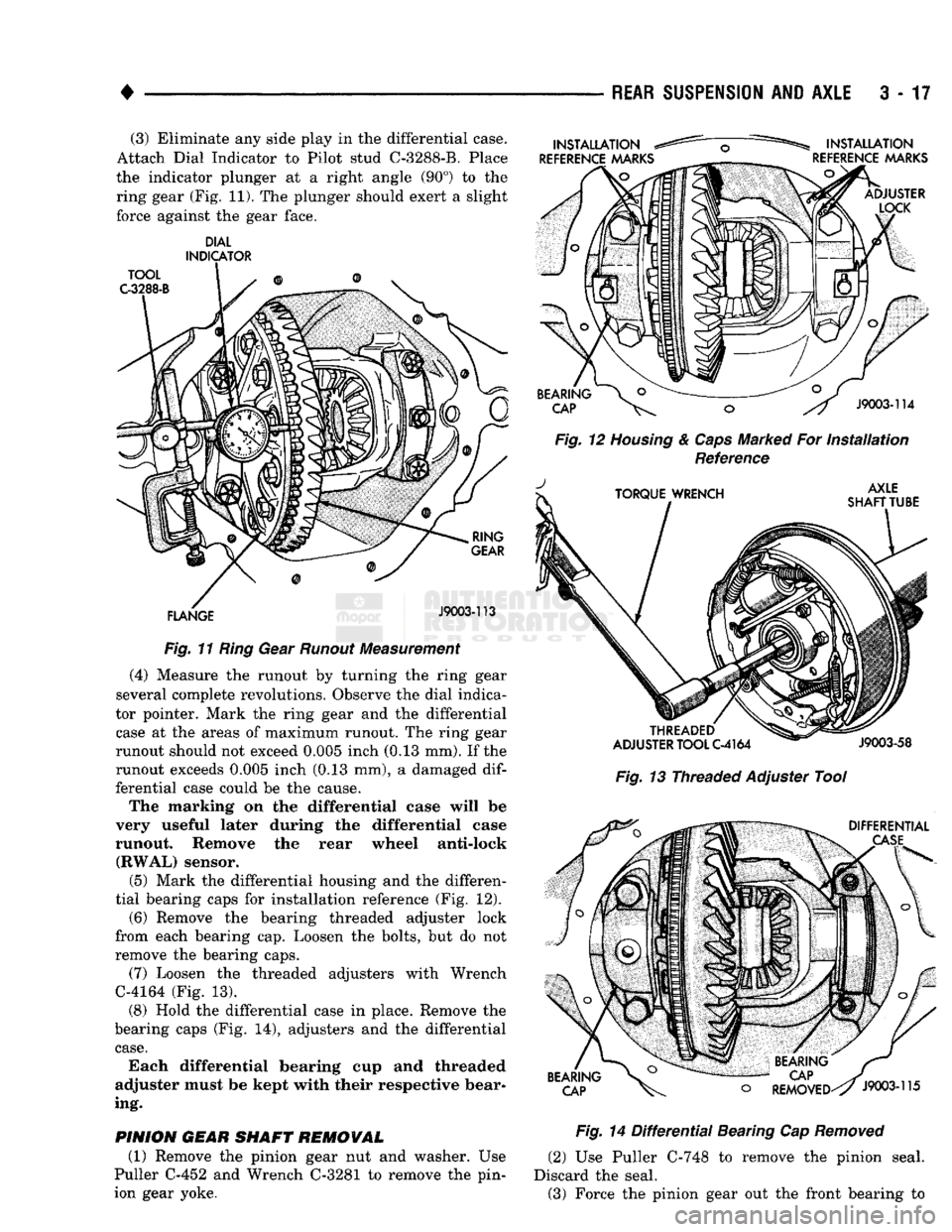
(3) Eliminate any side play in the differential case.
Attach Dial Indicator to Pilot stud C-3288-B. Place
the indicator plunger at a right angle (90°) to the ring gear (Fig. 11). The plunger should exert a slight
force against the gear face.
DIAL
INDICATOR
Fig.
11
Ring
Gear
Runout
Measurement
(4) Measure the runout by turning the ring gear
several complete revolutions. Observe the dial indica
tor pointer. Mark the ring gear and the differential
case at the areas of maximum runout. The ring gear
runout should not exceed 0.005 inch (0.13 mm). If the
runout exceeds 0.005 inch (0.13 mm), a damaged
dif
ferential case could be the cause.
The marking on the differential case will be
very useful later during the differential case
runout. Remove the rear wheel anti-lock (RWAL) sensor.
(5) Mark the differential housing and the differen
tial bearing caps for installation reference (Fig. 12).
(6) Remove the bearing threaded adjuster lock
from each bearing cap. Loosen the bolts, but do not
remove the bearing caps.
(7) Loosen the threaded adjusters with Wrench
C-4164 (Fig. 13).
(8) Hold the differential case in place. Remove the
bearing caps (Fig. 14), adjusters and the differential
case.
Each differential bearing cup and threaded
adjuster must be kept with their respective bear
ing.
PINION
GEAR
SHAFT
REMOVAL
(1) Remove the pinion gear nut and washer. Use
Puller C-452 and Wrench C-3281 to remove the pin
ion gear yoke.
Fig.
12
Housing
&
Caps
Marked For
Installation
Reference
Fig.
13 Threaded Adjuster Tool
Fig.
14
Differential
Bearing Cap
Removed
(2) Use Puller C-748 to remove the pinion seal.
Discard the seal. (3) Force the pinion gear out the front bearing to
Page 152 of 1502
REAR
SUSPENSION
AND
AXLE
3 - 2§
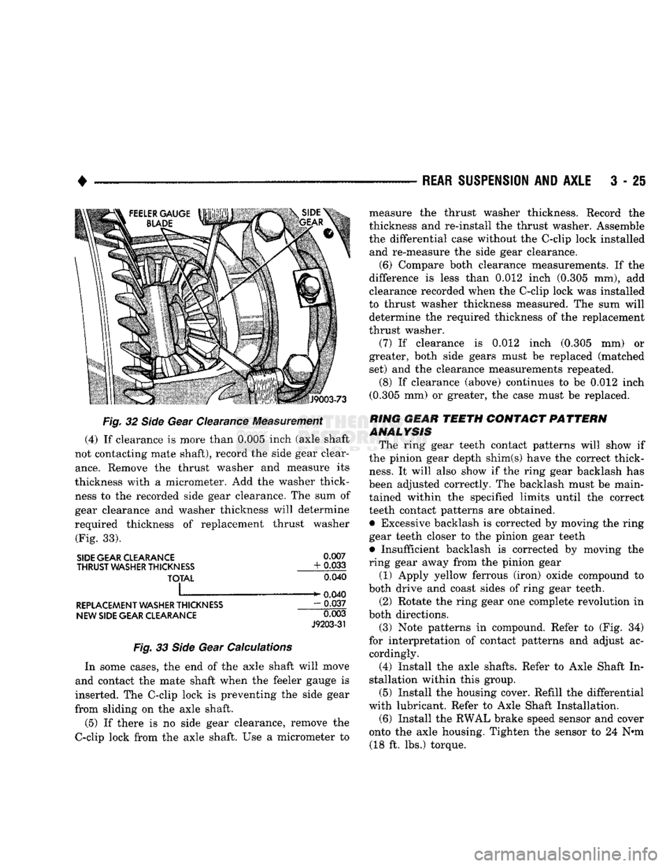
Fig.
32
Side
Gear Clearance Measurement
(4)
If
clearance
is
more than 0.005 inch (axle shaft
not contacting mate shaft), record
the
side gear clear
ance.
Remove
the
thrust washer
and
measure
its
thickness with
a
micrometer.
Add the
washer thick ness
to the
recorded side gear clearance.
The sum of
gear clearance
and
washer thickness will determine
required thickness
of
replacement thrust washer (Fig.
33).
SIDE GEAR CLEARANCE
0.007
THRUST
WASHER THICKNESS
+ 0.033
TOTAL
0.040
I ^ ^ 0.040
REPLACEMENT WASHER THICKNESS
- 0.037
NEW SIDE GEAR CLEARANCE
0.003
J9203-31
Fig.
33
Side
Gear Calculations
In some cases,
the end of the
axle shaft will move
and contact
the
mate shaft when
the
feeler gauge
is
inserted.
The
C-clip lock
is
preventing
the
side gear
from sliding
on the
axle shaft.
(5)
If
there
is no
side gear clearance, remove
the
C-clip lock from
the
axle shaft.
Use a
micrometer
to
measure
the
thrust washer thickness. Record
the
thickness
and
re-install
the
thrust washer. Assemble
the differential case without
the
C-clip lock installed and re-measure
the
side gear clearance.
(6) Compare both clearance measurements.
If the
difference
is
less than
0,012
inch (0.305
mm), add
clearance recorded when
the
C-clip lock
was
installed
to thrust washer thickness measured.
The sum
will determine
the
required thickness
of the
replacement
thrust washer.
(7)
If
clearance
is 0.012
inch (0.305
mm) or
greater, both side gears must
be
replaced (matched set)
and the
clearance measurements repeated.
(8)
If
clearance (above) continues
to be 0.012
inch
(0.305
mm) or
greater,
the
case must
be
replaced.
RING
GEAR
TEETH CONTACT PATTERN
ANALYSIS
The ring gear teeth contact patterns will show
if
the pinion gear depth shim(s) have
the
correct thick
ness.
It
will also show
if the
ring gear backlash
has
been adjusted correctly.
The
backlash must
be
main tained within
the
specified limits until
the
correct
teeth contact patterns
are
obtained.
• Excessive backlash
is
corrected
by
moving
the
ring gear teeth closer
to the
pinion gear teeth
• Insufficient backlash
is
corrected
by
moving
the
ring gear away from
the
pinion gear
(1) Apply yellow ferrous (iron) oxide compound
to
both drive
and
coast sides
of
ring gear teeth. (2) Rotate
the
ring gear
one
complete revolution
in
both directions.
(3) Note patterns
in
compound. Refer
to (Fig. 34)
for interpretation
of
contact patterns
and
adjust
ac
cordingly.
(4) Install
the
axle shafts. Refer
to
Axle Shaft
In
stallation within this group. (5) Install
the
housing cover. Refill
the
differential
with lubricant. Refer
to
Axle Shaft Installation.
(6) Install
the
RWAL brake speed sensor
and
cover
onto
the
axle housing. Tighten
the
sensor
to 24 N*m
(18
ft. lbs.)
torque.
Page 154 of 1502
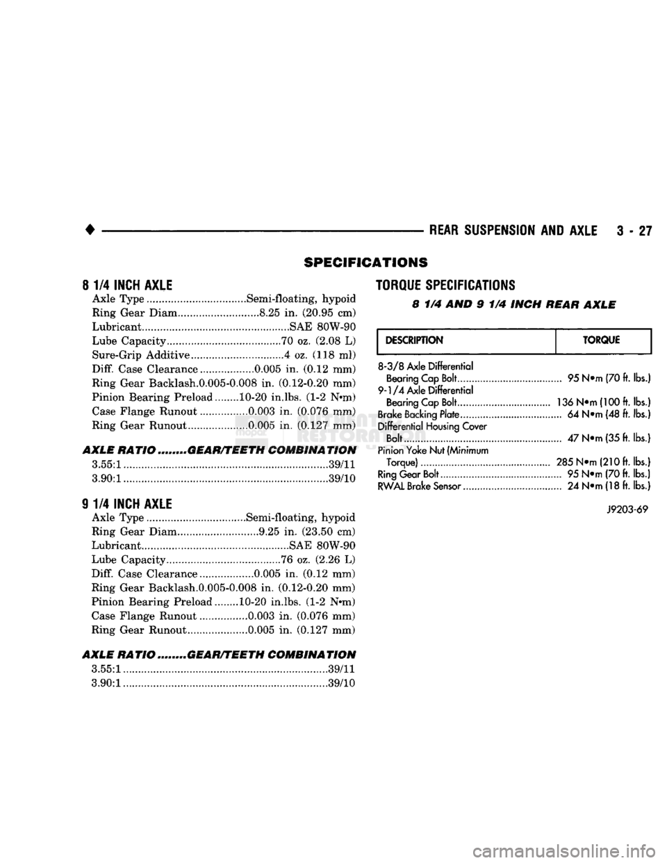
•
REAR
SUSPENSION
AND
AXLE
3 - 27
SPECIFICATIONS
8
1/4
INCH AXLE
Axle Type .Semi-floating, hypoid
Ring Gear Diam.. ....8.25
in.
(20.95 cm)
Lubricant............................. .........SAE 80W-90
Lube Capacity.....
70
oz. (2.08
L)
Sure-Grip Additive ....4 oz. (118
ml)
Diff.
Case Clearance.. 0.005
in.
(0.12 mm)
Ring Gear Backlash.0.005-0.008
in.
(0.12-0.20 mm)
Pinion Bearing Preload........ 10-20 in.lbs. (1-2 N*m) Case Flange Runout ................0.003
in.
(0.076 mm)
Ring Gear Runout ....0.005
in.
(0.127 mm)
AXLE
RATIOm„...,„GEAR/TEETH COMBINATION
3.55:1.....
39/11
3.90:1............
...............39/10
9
1/4
INCH AXLE
Axle Type .............Semi-floating, hypoid
Ring Gear Diam 9.25
in.
(23.50 cm)
Lubricant ....................SAE 80W-90
Lube Capacity ........76 oz. (2.26
L)
Diff.
Case Clearance 0.005
in.
(0.12 mm)
Ring Gear Backlash.0.005-0.008
in,
(0.12-0.20 mm)
Pinion Bearing Preload. 10-20 in.lbs. (1-2 Nnn) Case Flange Runout ................0.003
in.
(0.076 mm)
Ring Gear Runout..... .......0.005
in.
(0.127 mm)
AXLE
RATIO ........GEAR/TEETH COMBINATION
3.55:1.
.......39/11
3.90:1..............
39/10
TORQUE SPECIFICATIONS
8
1/4 AND 9 1/4
INCH
REAR AXLE
DESCRIPTION
TORQUE
8-3/8
Axle
Differential
Bearing Cap Bolt
9-1/4
Axle
Differential
Bearing Cap Bolt
Brake Backing
Plate
Differential
Housing
Cover
Bolt....
Pinion Yoke Nut (Minimum
Torque)
Ring
Gear Bolt
RWAL
Brake
Sensor...........
95 N*m (70 ft.
lbs.)
136 N»m(100ft.
lbs.!
... 64
N*m (48 ft. lbs.]
47
N»m
(35 ft.
lbs.)
285 N*m
(21
Oft. lbs.)
... 95
N*m (70 ft. lbs.)
... 24
N*m (18 ft.
lbs.)
J9203-69