1993 DODGE TRUCK sensor
[x] Cancel search: sensorPage 249 of 1502
i - 62
BRAKES
•
Isolation/Dump
Valve Cycle Times
Activation (opening/closing) of the isolation and
dump valves is continuous during antilock operation.
The valves cycle rapidly in response to speed sensor inputs and control module signal commands. Cycle
times are measured in milliseconds.
As the demand for antilock mode brake operation
is decreased, the module deactivates the hydraulic
valve components to restore normal brake operation.
ANTILOCK
SERVICE
DIAGNOSIS
GENERAL INFORMATION An antilock system malfunction will be indicated
by illumination of the amber antilock warning lamp.
The red brake warning lamp may also illuminate.
If a problem occurs, system diagnosis should begin
with a fluid level check followed by a visual exami
nation of the system electrical and hydraulic connec
tions.
If obvious defects (low fluid, leaks, loose connections, etc.) are not evident, road test the vehi
cle.
A road test should help determine if a malfunc
tion is actually related to an antilock component.
During the road test, note if other conditions are
evident such as a low pedal, pull, grab, or similar condition. Remember that brake malfunctions such as low fluid, system leaks, parking brakes partially
applied, will also affect the antilock system. The idea
is to determine if a malfunction is actually related to
an anti-lock component.
If a road test does reveal a problem, repeat the
road test with the owner driving. Make sure the owner is not riding the brake pedal, or has forgotten
to release the parking brakes. Either situation will
generate a fault and cause the antilock light to illu
minate.
SYSTEM FAULT
CODES
The antilock control module generates flash codes
to help identify the cause of an antilock system fault. Two different control modules are used with the
1992/1993 RWAL system. A type I module is used in
some early production models. All remaining produc
tion models are equipped with a type II module. The type I and II modules are identified by the way
fault codes 9 and 11 are processed. If the vehicle has a type I module, codes 9 and 11 are not erased when
the ignition switch is turned to Off position. If the vehicle has a type II module, codes 9 and 11 are
erased when the switch is turned to Off.
FAULT CODES WITH TYPE I CONTROL
MODULE
The microprocessor in the electronic control module
has a memory and a self test feature. The self test
feature is activated whenever the ignition switch is
turned to Accessory or Run position. If a system fault is detected, the control module il
luminates the antilock light and stores the fault code
in memory. Fault codes are retained in memory even after turning the ignition switch to Off position.
FAULT CODES WITH TYPE II CONTROL
MODULE The microprocessor in the electronic control module
has a memory and a self test feature. The self test
feature is activated whenever the ignition switch is
turned to Accessory or Run position.
If a system fault is detected, the control module
will illuminate the antilock indicator lamp and store
fault codes 1 through 8, 10 and 12 through 15 in the
microprocessor memory. When one of these fault
codes is generated, the control module will retain the code after the ignition switch is turned to the Off po
sition.
When fault code 9 is generated, the code only re
mains in microprocessor memory while the ignition switch is in Run position. Turning the ignition
switch to Off position erases fault code 9. However, if
the problem still exists when the switch is turned
back to Run position, code 9 will reappear in memory after 20 seconds and the antilock light will illumi
nate once again.
When fault code 11 is generated, the antilock light
will illuminate when vehicle speed exceeds approxi mately 60.35 km/h (37.5 mph). Code 11 only remains in memory while the ignition switch is in the Run
position and the fault is present.
When the cause of a fault code 11 is corrected, the
antilock light goes off. Code 11 is erased when the ig
nition switch is turned to Off position. However, if
the problem cause still exists when the ignition switch is turned to Run position, code 11 will reap
pear when vehicle speed exceeds approximately 60.35 km/h (37.5 mph).
FAULT
CODE
CAPACITY
The microprocessor memory will store and display
only one fault code at a time. The stored code can be
displayed by grounding the RWAL diagnostic connec
tor.
FAULT
CODE
IDENTIFICATION
To determine what the fault code is, momentarily
ground the RWAL diagnostic connector and count
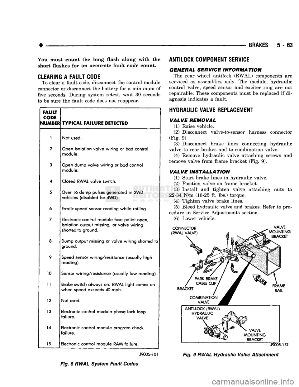
the number of times the amber antilock lamp flashes. Fault codes and typical malfunctions are outlined in Figure 8. Note that when a fault code is gen
erated, the red brake warning lamp will also
illuminate. The initial flash will be a long flash followed by a
number of short flashes. The long flash indicates the
beginning of the fault number sequence and the short flashes are a continuation of that sequence.
Page 250 of 1502
•
BRAKES
5 - 63 You must count the long flash along with the
short flashes for an accurate fault code count.
CLEARING
A
FAULT CODE
To clear a fault code, disconnect the control module
connector or disconnect the battery for a minimum of
five seconds. During system retest, wait 30 seconds
to be sure the fault code does not reappear.
FAULT
CODE
NUMBER
TYPICAL
FAILURE
DETECTED
1
Not used.
2
Open
isolation valve wiring
or
bad control
module.
3
Open
dump valve wiring
or
bad control
module.
4
Closed
RWAL
valve switch.
5
Over 16 dump pulses generated
in
2WD
vehicles (disabled
for
4WD).
6 Erratic speed sensor reading while rolling.
7 Electronic control module fuse
pellet
open,
isolation output
missing,
or
valve wiring
shorted to ground.
8
Dump
output
missing
or
valve wiring shorted
to
ground.
9
Speed
sensor wiring/resistance (usually high
reading).
10
Sensor
wiring/resistance (usually
low
reading).
11
Brake switch always on.
RWAL
light comes
on
when speed exceeds
40
mph.
12 Not used.
13 Electronic control module phase lock loop
failure.
14 Electronic control module program check
failure.
15 Electronic control module
RAM
failure.
J9005-101
Fig.
8
RWAL
System
Fault
Codes ANTILOCK COMPONENT SERVICE
GENERAL SERVICE INFORMATION
The rear wheel antilock (RWAL) components are
serviced as assemblies only. The module, hydraulic
control valve, speed sensor and exciter ring are not
repairable. These components must be replaced if di agnosis indicates a fault.
HYDRAULIC VALVE REPLACEMENT VALVE REMOVAL
(1) Raise vehicle.
(2)
Disconnect valve-to-sensor harness connector
(Fig. 9). (3) Disconnect brake lines connecting hydraulic
valve to rear brakes and to combination valve.
(4) Remove hydraulic valve attaching screws and
remove valve from frame bracket (Fig. 9).
VALVE INSTALLATION
(1) Start brake lines in hydraulic valve.
(2)
Position valve on frame bracket. (3) Install and tighten valve attaching nuts to
22-34 N-m (16-25 ft. lbs.) torque. (4) Tighten valve brake lines.
(5)
Bleed hydraulic valve and brakes. Refer to pro
cedure in Service Adjustments section.
(6)
Lower vehicle.
J9005-112
Fig.
9
RWAL
Hydraulic
Valve
Attachment
Page 251 of 1502
5
- 64
BRAKES
•
Fig.
10
Checking
CHECKING SPEED SENSOR
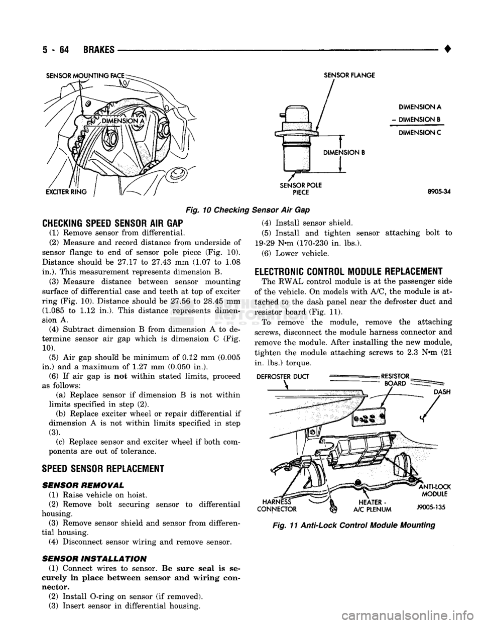
AIR GAP (1) Remove sensor from differential.
(2) Measure and record distance from underside of
sensor flange to end of sensor pole piece (Fig. 10).
Distance should be 27.17 to 27.43 mm (1.07 to 1.08
in.).
This measurement represents dimension B.
(3) Measure distance between sensor mounting
surface of differential case and teeth at top of exciter
ring (Fig. 10). Distance should be 27.56 to 28.45 mm (1.085 to 1.12 in,). This distance represents dimen
sion A.
(4) Subtract dimension B from dimension A to de
termine sensor air gap which is dimension C (Fig.
10).
(5) Air gap should be minimum of 0.12 mm (0.005
in.) and a maximum of 1.27 mm (0.050 in.). (6) If air gap is not within stated limits, proceed
as follows: (a) Replace sensor if dimension B is not within
limits specified in step (2). (b) Replace exciter wheel or repair differential if
dimension A is not within limits specified in step
(3).
(c) Replace sensor and exciter wheel if both com
ponents are out of tolerance.
SPEED
SENSOR REPLACEMENT
SENSOR
REMOVAL
(1) Raise vehicle on hoist.
(2) Remove bolt securing sensor to differential
housing.
(3) Remove sensor shield and sensor from differen
tial housing. (4) Disconnect sensor wiring and remove sensor.
SENSOR
INSTALLATION
(1) Connect wires to sensor. Be sure seal is se
curely in place between sensor and wiring con
nector. (2) Install O-ring on sensor (if removed). (3) Insert sensor in differential housing.
SENSOR
FLANGE
DIMENSION A
-
DIMENSION
B
DIMENSION C
SENSOR
POLE
PIECE
8905-34
Sensor
Air Gap (4) Install sensor shield.
(5) Install and tighten sensor attaching bolt to
19-29 Nnn (170-230 in. lbs.).
(6) Lower vehicle.
ELECTRONIC CONTROL MODULE REPLACEMENT
The RWAL control module is at the passenger side
of the vehicle. On models with A/C, the module is at
tached to the dash panel near the defroster duct and
resistor board (Fig. 11). To remove the module, remove the attaching
screws, disconnect the module harness connector and
remove the module. After installing the new module,
tighten the module attaching screws to 2.3 N»m (21 in. lbs.) torque.
Fig.
11
Anti-Lock
Control
Module
Mounting
Page 327 of 1502
8A
- 6
ELECTRICAL
•
Fig.
10
Load
50%
Cold
Crank
Rating Note Voltage
LOAD TEST TEMPERATURE
Minimum
Voltage
Temperature
Minimum
Voltage
P c°
9.6 70 and
above
21 and
above
9.5 60
16
9.4 50 10
9.3 40 4
9.1 30 -1
8.9 20 -7
8.7 10 -12
8.5 0
•
18
J908A-4
BATTERY
CHARGING
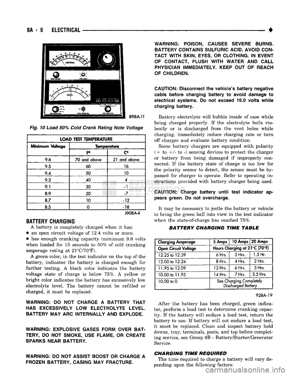
A battery is completely charged when it has:
• an open circuit voltage of 12.4 volts or more.
• has enough cranking capacity (minimum 9.6 volts
when loaded for 15 seconds to 50% of cold cranking amperage rating at 21°C/70°F). A green color, in the test indicator on the top of the
battery, indicates the battery is charged enough for
further testing. A black color indicates the battery
voltage state of charge is below 75%. A yellow or
bright color indicates the battery has excessively low electrolyte level. The battery cannot be refilled or
charged, it must be replaced.
WARNING:
DO NOT
CHARGE
A
BATTERY
THAT
HAS
EXCESSIVELY
LOW
ELECTROLYTE LEVEL.
BATTERY MAY ARC INTERNALLY AND EXPLODE.
WARNING: EXPLOSIVE GASES FORM OVER BAT
TERY,
DO NOT
SMOKE, USE FLAME,
OR
CREATE
SPARKS
NEAR BATTERY.
WARNING:
DO
NOT ASSIST BOOST
OR
CHARGE
A
FROZEN BATTERY, CASING MAY FRACTURE. WARNING: POISON, CAUSES SEVERE BURNS.
BATTERY CONTAINS SULFURIC ACID, AVOID CON
TACT WITH
SKIN,
EYES,
OR
CLOTHING.
IN
EVENT OF CONTACT, FLUSH
WITH
WATER
AND
CALL PHYSICIAN IMMEDIATELY. KEEP
OUT OF
REACH
OF CHILDREN.
CAUTION:
Disconnect
the
vehicle's
battery
negative
cable
before
charging
battery to
avoid
damage
to
electrical
systems.
Do not
exceed
16.0
volts
while
charging
battery.
Battery electrolyte will bubble inside of case while
being charged properly. If the electrolyte boils vio lently or is discharged from the vent holes while
charging, immediately reduce charging rate or turn
off charger and evaluate battery condition.
Some battery chargers are equipped with polarity
(+ to +/- to -) sensing devices to protect the charger
or battery from being damaged if improperly con
nected. If the battery state of charge is too low for
the polarity sensor to detect, the sensor must be by
passed for charger to operate. Refer to operating in structions provided with battery charger being used.
CAUTION:
Charge
battery
until
test
indicator
ap
pears
green.
Do not
overcharge.
It may be necessary to jostle the battery or vehicle
to bring the green ball into view in the test indicator
when the state-of-charge has reached 75%.
BATTERY CHARGING TIME TABLE
Charging
Amperage
5 Amps
10 Amps
20 Amps
Open
Circuit
Voltage
Hours
Charging
at21°C
(70°F)
12.25
to
12.39
6Hrs.
3Hrs.
1.5
Hr.
12.00
to
12.24
8Hrs.
4Hrs.
2Hrs
11.95
to
12.09
12Hrs.
6Hrs.
3Hrs.
10.00
to
11.95
14Hrs.
7Hrs.
3.5 Hrs.
10.00 to
0
See
Charging
Completely
Discharged
Battery
928A-19
After the battery has been charged, green indica
tor, perform a load test to determine cranking capac ity. If the battery will endure a load test, return the
battery to use. If battery will not endure a load test, it must be replaced. Clean and inspect battery hold
downs, tray, terminals, posts, and top before complet
ing service, see Group 8B - Battery/Starter/Generator Service.
CHARGING TIME REQUIRED The time required to charge a battery will vary de
pending upon the following factors:
Page 338 of 1502
•
ELECTRICAL
8A - 17
DIAGNOSTIC
TROUBLE
CODES
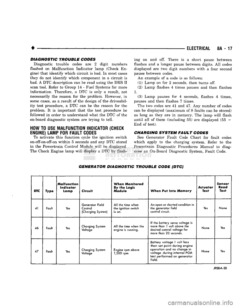
Diagnostic trouble codes are 2 digit numbers
flashed on Malfunction Indicator lamp (Check En
gine) that identify which circuit is bad. In most cases
they do not identify which component in a circuit is
bad. A DTC description can be read using the DRB II scan tool. Refer to Group 14 - Fuel Systems for more
information. Therefore, a DTC is only a result, not
necessarily the reason for the problem. However, in
some cases, as a result of the design of the driveabil- ity test procedure, a DTC can be the reason for the
problem. It is important that the test procedure be followed in order to understand what the DTC of the
on-board diagnostic system are trying to tell.
HOW
TO
USE
MALFUNCTION
INDICATOR
(CHECK
ENGINE)
LAMP
FOR
FAULT
CODES
To activate this function cycle the ignition switch
on-off-on-off-on within 5 seconds and any DTC stored
in the Powertrain Control Module will be displayed.
The Check Engine lamp will display a DTC by flash ing on and off. There is a short pause between
flashes and a longer pause between digits. All codes
displayed are two digit numbers with a four second
pause between codes. An example of a code is as follows:
(1) Lamp on for 2 seconds, then turns off.
(2) Lamp flashes 4 times pauses and then flashes
1.
(3) Lamp pauses for 4 seconds, flashes 4 times,
pauses and then flashes 7 times.
The two codes are 41 and 47. Any number of codes
can be displayed (maximum of 8 faults can be stored) as long as they are in memory. The lamp will flash
until all of them (including 55) are displayed (55 =
End of test).
CHARGING
SYSTEM
FAULT
CODES
See Generator Fault Code Chart for fault codes
which apply to the charging system. Refer to the
Powertrain Diagnostic Procedures Manual to diag
nose an On-Board Diagnostic System, Fault Code.
GENERATOR
DIAGNOSTIC
TROUBLE
CODE
(DTC)
DTC
Type
Malfunction
Indicator
Lamp
Circuit
When
Monitored
By
the
Logic
Module
When
Put Into
Memory
Actuator
Test
Sensor
Read
Test
41 Fault
Yes
Generator Field
Control
(Charging
System)
All the
time
when
the ignition switch
is
on.
An
open or shorted condition in
the generator
field
control circuit.
Yes
None
46 Fault
Yes
Charging
System
Voltage
All the
time
when the
engine
is
running.
If the
battery
sense
voltage is
more than 1 volt
above
the
desired
control voltage for
more than 20
seconds.
None
Yes
47 Fault
Yes
Charging
System
Voltage
Engine
rpm
above
1,500 rpm Battery voltage
1
volt
less
than set point during engine
operation and no
change
in
voltage
during
internal
PCM
test performed on generator field.
None
Yes
J938A-20
Page 352 of 1502
•
IGNITION
SYSTEMS
8D
- 1
CONTENTS
page page
COMPONENT IDENTIFICATION/SYSTEM DIAGNOSTICS/SERVICE PROCEDURES
7
OPERATION
1
IGNITION SWITCH
25
COMPONENT REMOVAL/INSTALLATION
..... 18
SPECIFICATIONS
28
COMPONENT
IDENTIFICATION/SYSTEM OPERATION
INDEX
page
Automatic
Shut Down (ASD) Relay
1
Camshaft Position Sensor
2
Crankshaft Position Sensor
2
Distributors
3
Engine Coolant
Temperature
Sensor
...........
4
General
Information
1
page
Ignition
Coil
3
Intake
Manifold Charge
Air
Temperature
Sensor
. . 4
Manifold Absolute Pressure (MAP) Sensor
4
Powertrain
Control
Module (PCM)
. 5
Throttle
Position Sensor
5
GENERAL
INFORMATION
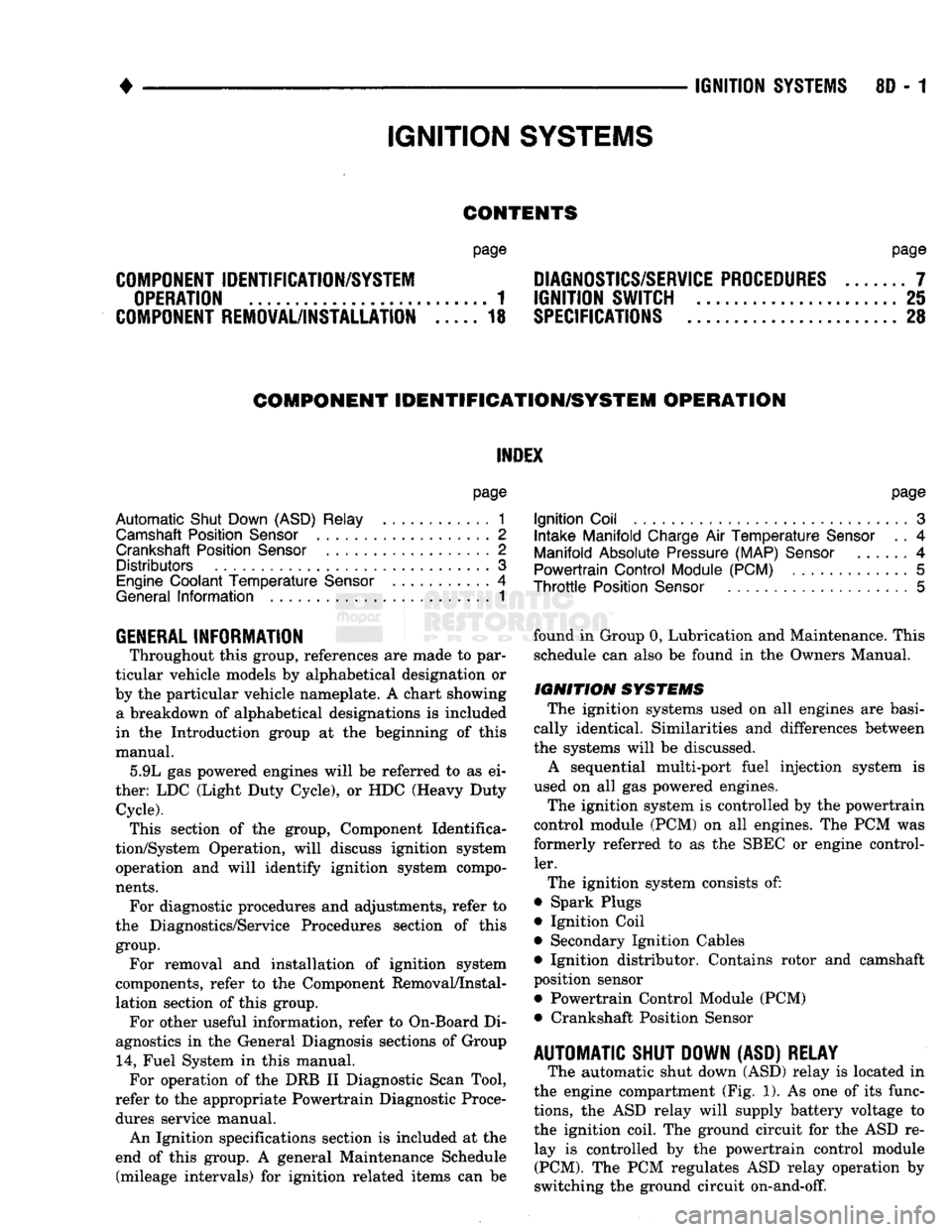
Throughout this group, references
are
made
to
par
ticular vehicle models
by
alphabetical designation
or
by
the
particular vehicle nameplate.
A
chart showing a breakdown
of
alphabetical designations
is
included
in
the
Introduction group
at the
beginning
of
this
manual. 5.9L
gas
powered engines will
be
referred
to as ei
ther: LDC (Light Duty Cycle),
or
HDC (Heavy Duty Cycle). This section
of the
group, Component Identifica
tion/System Operation, will discuss ignition system operation
and
will identify ignition system compo
nents.
For diagnostic procedures
and
adjustments, refer
to
the Diagnostics/Service Procedures section
of
this
group.
For removal
and
installation
of
ignition system
components, refer
to the
Component Removal/Instal
lation section
of
this group. For other useful information, refer
to
On-Board
Di
agnostics
in the
General Diagnosis sections
of
Group
14,
Fuel System
in
this manual. For operation
of the DRB II
Diagnostic Scan Tool,
refer
to the
appropriate Powertrain Diagnostic Proce
dures service manual.
An Ignition specifications section
is
included
at the
end
of
this group.
A
general Maintenance Schedule (mileage intervals)
for
ignition related items
can be
found
in
Group
0,
Lubrication and Maintenance. This
schedule
can
also
be
found
in the
Owners Manual.
IGNITION
SYSTEMS
The ignition systems used
on all
engines
are
basi
cally identical. Similarities
and
differences between
the systems will
be
discussed.
A sequential multi-port fuel injection system
is
used
on all gas
powered engines.
The ignition system
is
controlled
by the
powertrain
control module (PCM)
on all
engines.
The
PCM
was
formerly referred
to as the
SBEC
or
engine control ler.
The ignition system consists
of:
• Spark Plugs
• Ignition Coil
• Secondary Ignition Cables
• Ignition distributor. Contains rotor
and
camshaft
position sensor • Powertrain Control Module (PCM)
• Crankshaft Position Sensor
AUTOMATIC SHUT DOWN (ASD) RELAY
The automatic shut down (ASD) relay
is
located
in
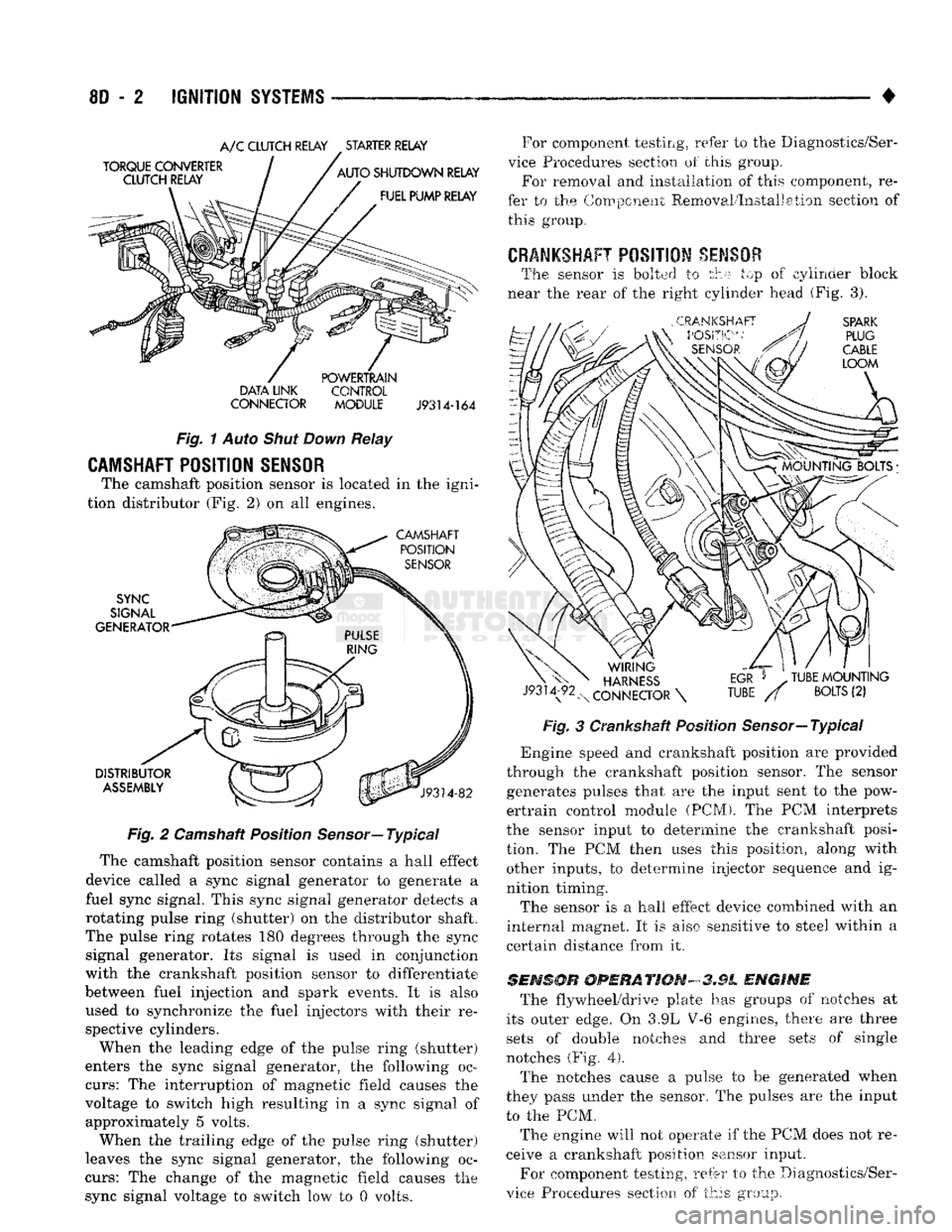
the engine compartment (Fig.
1). As one of its
func
tions,
the ASD
relay will supply battery voltage
to
the ignition coil.
The
ground circuit
for the
ASD
re
lay
is
controlled
by the
powertrain control module (PCM).
The PCM
regulates
ASD
relay operation
by
switching
the
ground circuit on-and-off.
IGNITION
SYSTEMS
Page 353 of 1502
8D
- 2
IGNITION
SYSTEMS
•
A/C
CLUTCH RELAY STARTER RELAY
DATA LINK CONTROL
CONNECTOR
MODULE J9314-164
Fig.
1
Auto
Shut Down
Relay
CAMSHAFT POSITION SENSOR
The camshaft position sensor is located in the igni
tion distributor (Fig. 2) on all engines.
Fig.
2 Camshaft Position
Sensor—
Typical
The camshaft position sensor contains a hall effect
device called a sync signal generator to generate a
fuel sync signal. This sync signal generator detects a
rotating pulse ring (shutter) on the distributor shaft.
The pulse ring rotates 180 degrees through the sync signal generator. Its signal is used in conjunction
with the crankshaft position sensor to differentiate
between fuel injection and spark events. It is also
used to synchronize the fuel injectors with their re spective cylinders.
When the leading edge of the pulse ring (shutter)
enters the sync signal generator, the following oc
curs:
The interruption of magnetic field causes the
voltage to switch high resulting in a sync signal of approximately 5 volts.
When the trailing edge of the pulse ring (shutter)
leaves the sync signal generator, the following oc
curs:
The change of the magnetic field causes the sync signal voltage to switch low to 0 volts. For component testing, refer to the Diagnostics/Ser
vice Procedures section of this group. For removal and installation of this component, re
fer to the Component Removal/Installation section of this group.
CRANKSHAFT
POSITION
SENSOR
The sensor is bolted to the top of cylinder block
near the rear of the right cylinder head (Fig. 3).
Fig.
3 Crankshaft Position Sensor—Typical
*
Engine speed and crankshaft position are provided
through the crankshaft position sensor. The sensor generates pulses that are the input sent to the pow
ertrain control module (PCM). The PCM interprets
the sensor input to determine the crankshaft posi
tion. The PCM then uses this position, along with other inputs, to determine injector sequence and ig
nition timing.
The sensor is a hall effect device combined with an
internal magnet. It is also sensitive to steel within a
certain distance from it.
SENSOR
OPERATION-3.9L
ENGINE
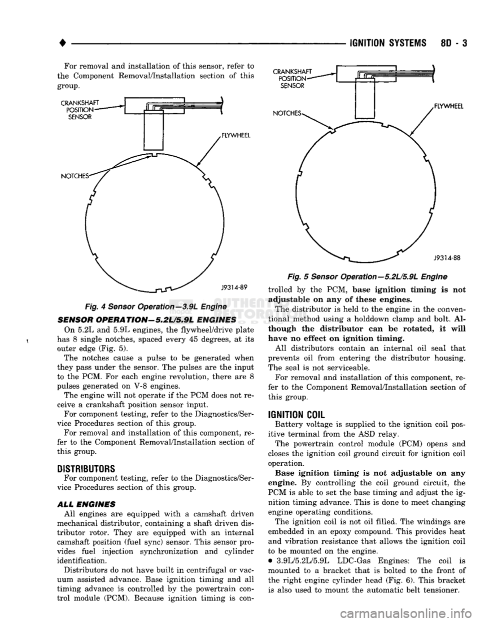
The flywheel/drive plate has groups of notches at
its outer edge. On 3.9L V-6 engines, there are three sets of double notches and three sets of single
notches (Fig.
4).
The notches cause a pulse to be generated when
they pass under the sensor. The pulses are the input to the PCM.
The engine will not operate if the PCM does not re
ceive a crankshaft position sensor input.
For component testing, refer to the Diagnostics/Ser
vice Procedures section of this group.
Page 354 of 1502
•
IGNITION
SYSTEMS
8D - 3 For removal and installation of this sensor, refer to
the Component Removal/Installation section of this
group.
CRANKSHAFT
POSITION
SENSOR
NOTCHES- FLYWHEEL CRANKSHAFT
POSITION-
SENSOR
NOTCHES* .FLYWHEEL
J9314-88
—^^j^jV^
J9314-89
Fig.
4
Sensor
Operation—3.9L
Engine
SENSOR
OPERATION'-5.2U5.9L
ENGINES On 5.2L and 5.9L engines, the flywheel/drive plate
has 8 single notches, spaced every 45 degrees, at its outer edge (Fig. 5).
The notches cause a pulse to be generated when
they pass under the sensor. The pulses are the input to the PCM. For each engine revolution, there are 8
pulses generated on V-8 engines.
The engine will not operate if the PCM does not re
ceive a crankshaft position sensor input. For component testing, refer to the Diagnostics/Ser
vice Procedures section of this group.
For removal and installation of this component, re
fer to the Component Removal/Installation section of
this group.
DISTRIBUTORS
For component testing, refer to the Diagnostics/Ser
vice Procedures section of this group.
ALL
ENGINES All engines are equipped with a camshaft driven
mechanical distributor, containing a shaft driven dis
tributor rotor. They are equipped with an internal camshaft position (fuel sync) sensor. This sensor pro
vides fuel injection synchronization and cylinder identification.
Distributors do not have built in centrifugal or vac
uum assisted advance. Base ignition timing and all
timing advance is controlled by the powertrain con
trol module (PCM). Because ignition timing is con-
Fig.
5
Sensor
Opera tion—5.2L/5.9L
Engine
trolled by the PCM, base ignition timing is not adjustable on any of these engines.
The distributor is held to the engine in the conven
tional method using a holddown clamp and bolt. Al
though the distributor can be rotated, it will
have no effect on ignition timing.
All distributors contain an internal oil seal that
prevents oil from entering the distributor housing.
The seal is not serviceable.
For removal and installation of this component, re
fer to the Component Removal/Installation section of
this group.
IGNITION
COIL
Battery voltage is supplied to the ignition coil pos
itive terminal from the ASD relay. The powertrain control module (PCM) opens and
closes the ignition coil ground circuit for ignition coil operation. Base ignition timing is not adjustable on any
engine. By controlling the coil ground circuit, the
PCM is able to set the base timing and adjust the ig nition timing advance. This is done to meet changing engine operating conditions. The ignition coil is not oil filled. The windings are
embedded in an epoxy compound. This provides heat and vibration resistance that allows the ignition coil
to be mounted on the engine. • 3.9L/5.2L/5.9L LDC-Gas Engines: The coil is
mounted to a bracket that is bolted to the front of the right engine cylinder head (Fig. 6). This bracket is also used to mount the automatic belt tensioner.