1993 DODGE TRUCK sensor
[x] Cancel search: sensorPage 391 of 1502
8E
- 10
INSTRUMENT
PANEL
AND
GAUGES
GROUND
OIL
PRESSURE
SENSOR
INPUT
J908E-70
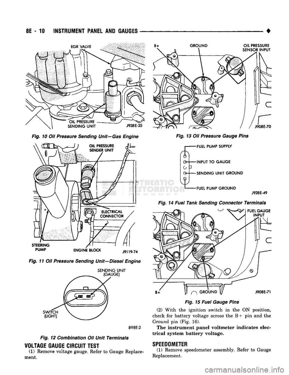
Fig.
10 Oil Pressure
Sending
Unit—Gas Engine
STEERING
PUMP
ENGINE
BLOCK
J9119-74
Fig.
11 Oil Pressure
Sending
Unit—Diesel Engine
SENDING
UNIT
(GAUGE)
SWITCH
(LIGHT)
898E-2
Fig.
12 Combination Oil Unit Terminals
VOLTAGE
GAUGE
CIRCUIT
TEST
(1) Remove voltage gauge. Refer to Gauge Replace
ment.
Fig.
13 Oil Pressure
Gauge
Pins
r— FUEL
PUMP
SUPPLY
0 INPUT TO
GAUGE
-SENDING
UNIT
GROUND
-FUEL
PUMP
GROUND
J928E-49
Fig.
14 Fuel Tank
Sending
Connector Terminals
FUEL
GAUGE
INPUT
^
GROUND
y
J908E-71
Fig.
15 Fuel
Gauge
Pins
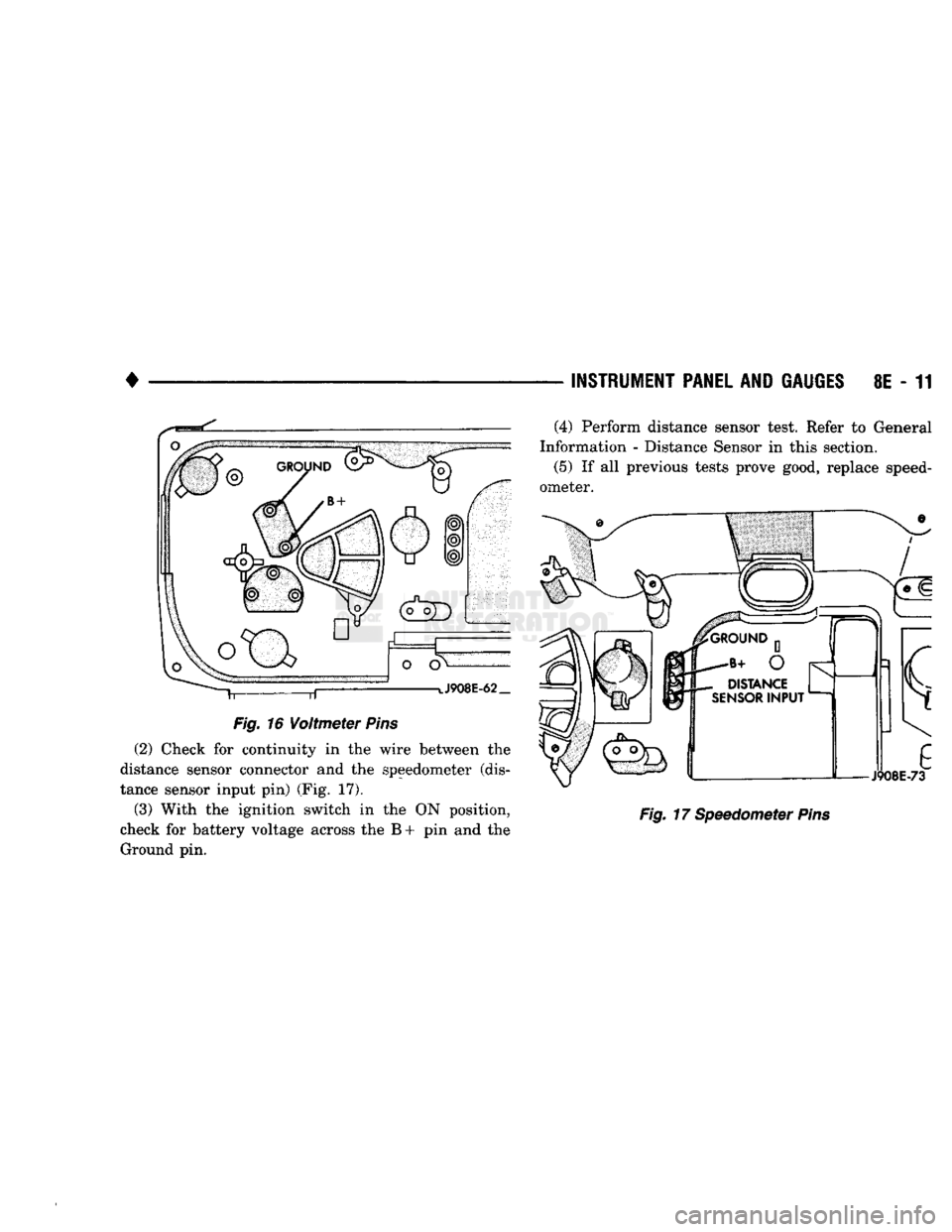
(2) With the ignition switch in the ON position,
check for battery voltage across the B+ pin and the Ground pin (Fig. 16).
The instrument panel voltmeter indicates elec
trical system battery voltage.
SPEEDOMETER
(1) Remove speedometer assembly. Refer to Gauge
Replacement.
Page 392 of 1502
•
Fig.
16
Voltmeter
Pins
(2) Check for continuity in the wire between the
distance sensor connector and the speedometer (dis
tance sensor input pin) (Fig. 17).
(3) With the ignition switch in the ON position,
check for battery voltage across the B + pin and the Ground pin. —
INSTRUMENT PANEL
AND
GAUGES
8E - 11
Fig.
17 Speedometer
Pins
(4) Perform distance sensor test. Refer to General
Information - Distance Sensor in this section.
(5)
If all previous tests prove good, replace speed
ometer.
Page 419 of 1502
8H - 4 VEHICLE
SPEED
CONTROL SYSTEM
GAS
ENGINE
CONTINUED
UNIT
DISENGAGES
ON ROUGH ROAD
IMPROPER
ADJUSTMENT OF STOP LAMP AND SPEED
CONTROL SWITCH*
FAULTY
ELECTRICAL CIRCUIT
£
ENGINE DOES
NOT RETURN TO NORMAL IDLE
SPEED
CONTROL
THROTTLE
CABLE
KINKED OR DAMAGED
STANDARD
THROTTLE
LINKAGE FAULTS 1
DRIVE VEHICLE OVER
ROUGH ROAD
TAP BRAKE PEDAL
LIGHTLY,
SPEED
CONTROL SHOULD
DISENGAGE
SPEED
CONTROL
DISENGAGES
PUSH RESUME/ACCEL SWITCH VEHICLE
SHOULD RESUME PREVIOUSLY
MEMORIZED SPEED
VEHICLE RESUMES
SPEED
DEPRESS
BRAKE
PEDAL,
SPEED CONTROL
SHOULD DISENGAGE NO SYSTEM
DISENGAGEMENT
WHEN MAKE PEDAL
IS
DEPRESSED
DEFECTIVE OR
IMPROPERLY ADJSUTED
STOP LAMP AND
SPEED
CONTROL SWITCH
y
f
SPEED
CONTROL
THROTTLE
CABLE
KINKED OR DAAAAGED
1
FAULTY
ELECTRICAL CIRCUIT*
f
DEFECTIVE SERVO NO RESUME WHEN
BUTTON
IS
PRESSED
SPEED
CONTROL
DISENGAGES
DEFECTIVE SWITCH
FAULTY
ELECTRICAL CIRCUIT* NO SYSTEM
DISENGAGE
WHEN BRAKE PEDAL IS
DEPRESSED
SPEED
CONTROL
SYSTEM OK
1
f
DEFECTIVE ENGINE CONTROLLER
1
FAULTY
ELECTRICAL CIRCUIT*
r
STICKY BRAKE SWITCH RESUM
ISPO
BELOW
2
E
SPEED
SSIBLE
10
M.P.H.
y t
DEFECTIVE DISTANCE
SENSOR
y f
DEFECTIVE
ENGINE CONTROLLER
J928H-14
Page 421 of 1502
- 6
VEHICLE SPEED CONTROL SYSTEM
• £
UNIT
DISENGAGES
ON ROUGH ROAD
IMPROPER
ADJUSTMENT
OF
STOP LAMP AND SPEED
CONTROL SWITCH*
i
FAULTY
ELECTRICAL CIRCUIT
ENGINE DOES
NOT RETURN
TO
NORMAL IDLE
SPEED
CONTROL
THROTTLE
CABLE
KINKED OR DAAAAGED
STANDARD
THROTTLE
LINKAGE FAULTS
NO RESUME WHEN
BUTTON
IS
PRESSED
DRIVE VEHICLE OVER
ROUGH ROAD
±
TAP BRAKE PEDAL
LIGHTLY,
SPEED
CONTROL SHOULD
DISENGAGE
SPEED
CONTROL
DISENGAGES
PUSH RESUME/ACCEL SWITCH VEHICLE
SHOULD RESUME PREVIOUSLY
MEMORIZED SPEED
VEHICLE RESUMES
SPEED
DEPRESS
BRAKE
PEDAL,
SPEED CONTROL
SHOULD DISENGAGE NO SYSTEM
DISENGAGEMENT
WHEN MAKE PEDAL
IS
DEPRESSED
DEFECTIVE OR
IMPROPERLY ADJSUTED STOP LAMP
AND
SPEED
CONTROL SWITCH
1
1
SPEED
CONTROL
THROTTLE
CABLE
KINKED
OR
DAAAAGED
1
FAULTY
ELECTRICAL CIRCUIT*
1
DEFECTIVE SERVO
SPEED
CONTROL
DISENGAGES
DEFECTIVE SWITCH
FAULTY
ELECTRICAL CIRCUIT*
1
NO SYSTEM
DISENGAGE
WHEN BRAKE PEDAL
IS
DEPRESSED
SPEED
CONTROL
SYSTEM
OK
1
r
DEFECTIVE ENGINE CONTROLLER
* r
FAULTY
ELECTRICAL CIRCUIT*
r
STICKY BRAKE SWITCH RESUM
ISPO
BELOW*
E
SPEED
SSIBLE
10
M.P.H.
1
DEFECTIVE DISTANCE
SENSOR
f
DEFECTIVE
ENGINE CONTROLLER
J928H-14 DIESEL ENGINE CONTINUED
Page 422 of 1502
•
VEHICLE
SPEED
CONTROL SYSTEM
8H - 7
TEST
PROCEDURES
INDEX
page
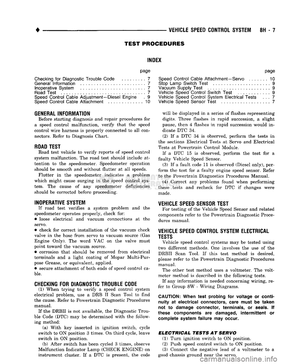
Checking
for
Diagnostic
Trouble
Code
7
General
Information
7
Inoperative
System
7
Road
Test
7
Speed
Control
Cable Adjustment—Diesel Engine
. 9
Speed
Control
Cable
Attachment
10
GENERAL
INFORMATION
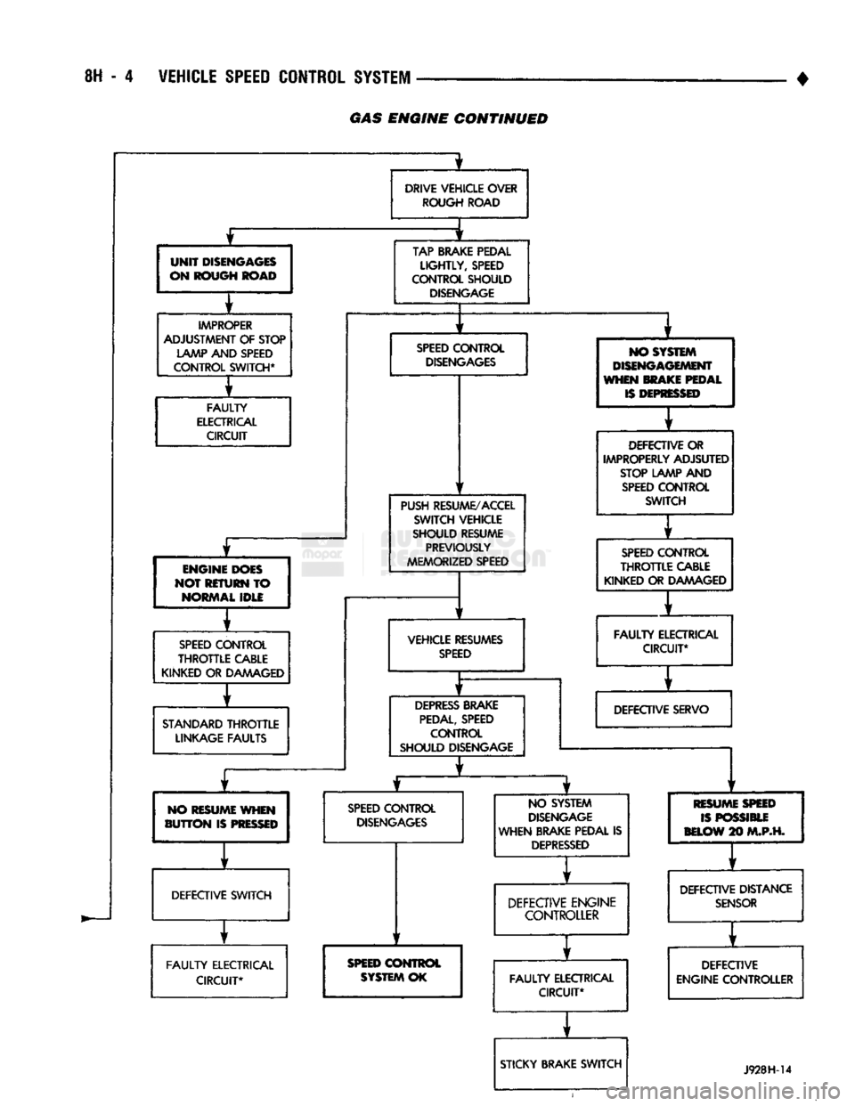
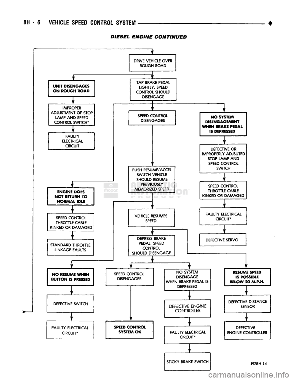
Before starting diagnosis and repair procedures for
a speed control malfunction, verify that the speed
control wire harness is properly connected to all con nectors. Refer to Diagnosis Chart.
ROAD
TEST
Road test vehicle to verify reports of speed control
system malfunction. The road test should include at
tention to the speedometer. Speedometer operation should be smooth and without flutter at all speeds. Flutter in the speedometer indicates a problem
which might cause surging in the speed control sys
tem. The cause of any speedometer deficiencies should be corrected before proceeding.
INOPERATIVE SYSTEM
If road test verifies a system problem and the
speedometer operates properly, check for:
• loose electrical and vacuum connections at the
servo.
• check for correct installation of the vacuum check
valve in the hose from servo to vacuum source (Gas
Engine Only). The word VAC on the valve must
point toward the vacuum source. • corrosion that should be removed from electrical
terminals and a light coating of Mopar Multi-Pur
pose Grease, or equivalent, applied. • secure attachment of both ends of speed control ca
ble.
CHECKING
FOR DIAGNOSTIC TROUBLE CODE
(1) When trying to verify a speed control system
electrical problem, use a DRB II Scan Tool to find
the cause. Refer to Powertrain Diagnostic Procedures manual. If the DRBII is not available, the Diagnostic Trou
ble Code (DTC) may be determined with the follow ing method: (a) With key inserted in ignition switch, cycle
switch to ON position 3 times. On third cycle, leave
switch in ON position. (b) After switch has been cycled 3 times, observe
Malfunction Indicator Lamp (CHECK ENGINE) on instrument cluster. If a DTC is present, the code
page
Speed
Control
Cable Attachment—Servo
10
Stop Lamp Switch Test
9
Vacuum Supply Test
....................... 9
Vehicle Speed
Control
Switch Test
. 9
Vehicle Speed
Control
System
Electrical
Tests
... 7
Vehicle Speed Sensor Test
7
will be displayed in a series of flashes representing
digits.
Three flashes in rapid succession, a slight
pause, then 4 flashes in rapid succession would in dicate DTC 34.
(2) If a DTC 34 is observed, perform the tests in
the sections Electrical Tests at Servo and Electrical
Tests at Powertrain Control Module.
If a DTC 15 is observed, perform the test for a
faulty Vehicle Speed Sensor.
(3) If a fault code 11 is observed (Diesel only), per
form the test for a faulty engine speed sensor. Refer
to the Powertrain Diagnostics Procedures Manual.
(4) Correct any problems found when performing
these tests and recheck for DTC if changes were made.
VEHICLE SPEED SENSOR TEST
For testing of the Vehicle Speed Sensor and related
components refer to the Powertrain Diagnostic Proce
dures manual.
VEHICLE SPEED CONTROL SYSTEM ELECTRICAL
TESTS
Vehicle speed control systems may be tested using
two different methods. One involves the use of the DRBII Scan Tool. If this test method is desired,
please refer to the Powertrain Diagnostic Procedures manual. The other test method uses a voltmeter. The volt
meter method is described in the following tests.
If any information is needed concerning wiring, re
fer to Group 8W - Wiring Diagrams.
CAUTION:
When test probing
for
voltage
or
continuity
at
electrical
connectors, care must
be
taken
not
to
damage connector, terminals,
or
seals.
If
these components
are
damaged,
intermittent
or
complete system
failure
may
occur.
ELECTRICAL
TESTS
AT
SERVO
(1) Turn ignition switch to ON position.
(2) Push speed control switch to ON position.
(3) Connect the negative lead of a voltmeter to a
good chassis ground near the servo.
Page 451 of 1502
8L
- 8
LAMPS
CONNECTOR
CUP
FRONT
LAMP
ASSEMBLY
LICENSE
PLATE
SCREW
LAMP
ASSEMBLY
LICENSE
PLATE
RR8LD24
Fig.
15
License
Plate
Lamps
-
Step
Bumper
TO
TAIL,
STOP,
TURN
SIG. AND
BACK
UP
LAMPS
LICENSE
PLATE
LICENSE
PLATE
LAMP
AND
LAMP
CONNECTOR
BRACKET
ASSEMBLY
J908L-74
Fig.
16
License
Plate
Lamp
Without Rear
Bumper
UNDERHOOD
LAMP
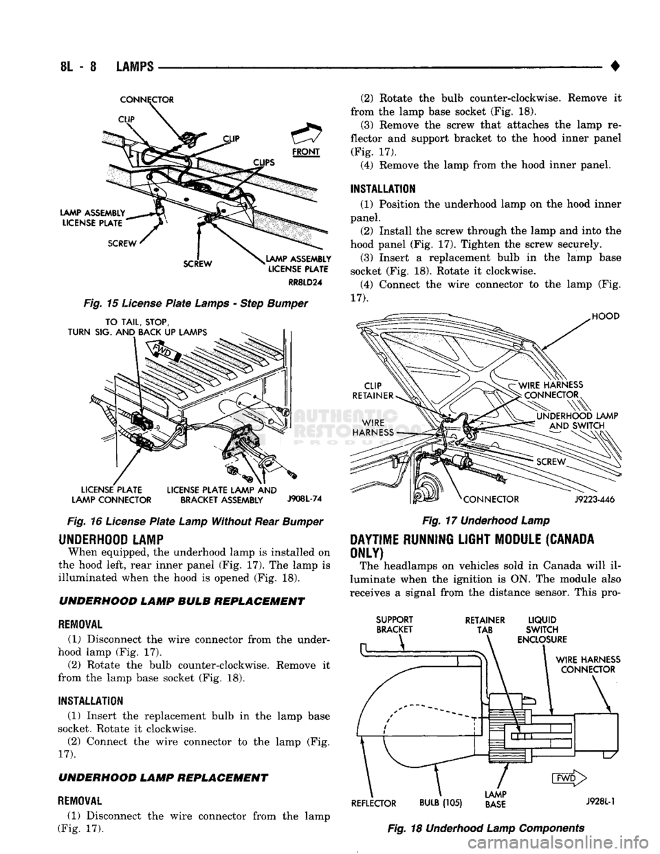
When equipped, the underhood lamp is installed on
the hood left, rear inner panel (Fig, 17). The lamp is
illuminated when the hood is opened (Fig. 18). UNDERHOOD LAMP BULB REPLACEMENT
REMOVAL
(1) Disconnect the wire connector from the under
hood lamp (Fig. 17).
(2) Rotate the bulb counter-clockwise. Remove it
from the lamp base socket (Fig. 18).
INSTALLATION
(1) Insert the replacement bulb in the lamp base
socket. Rotate it clockwise.
(2) Connect the wire connector to the lamp (Fig.
17).
UNDERHOOD LAMP REPLACEMENT
REMOVAL
(1) Disconnect the wire connector from the lamp
(Fig. 17). (2) Rotate the bulb counter-clockwise. Remove it
from the lamp base socket (Fig. 18). (3) Remove the screw that attaches the lamp re
flector and support bracket to the hood inner panel (Fig. 17).
(4) Remove the lamp from the hood inner panel.
INSTALLATION (1) Position the underhood lamp on the hood inner
panel. (2) Install the screw through the lamp and into the
hood panel (Fig. 17). Tighten the screw securely. (3) Insert a replacement bulb in the lamp base
socket (Fig. 18). Rotate it clockwise. (4) Connect the wire connector to the lamp (Fig.
17).
HOOD
J9223-446
Fig.
17
Underhood
Lamp
DAYTIME
RUNNING
LIGHT
MODULE
(CANADA
ONLY)
The headlamps on vehicles sold in Canada will il
luminate when the ignition is ON. The module also
receives a signal from the distance sensor. This pro-
SUPPORT
BRACKET RETAINER
LIQUID
TAB SWITCH
ENCLOSURE
WIRE
HARNESS
CONNECTOR
\
1
d1^—1—l
L/
CMD>
LAMP
REFLECTOR
BULB
(105)
BASE
J9281"1
Fig.
18
Underhood
Lamp
Components
Page 477 of 1502
8W
- 2
WIRING
DIAGRAMS
•
WIRE CODE
IDENTIFICATION
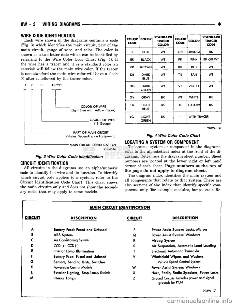
Each wire shown in the diagrams contains a code
(Fig. 3) which identifies the main circuit, part of the
main circuit, gauge of wire, and color. The color is shown as a two letter code which can be identified by
referring to the Wire Color Code Chart (Fig. 4). If
the wire has a tracer and it is a standard color an asterisk will follow the main wire color. If the tracer
is non-standard the main wire color will have a slash (/) after it followed by the tracer color. 18
LB/YL*
COLOR
OF
WIRE
(Light
Blue
with
Yellow
Tracer)
.
GAUGE
OF
WIRE
(18
Gauge)
PART
OF
AAAIN CIRCUIT
(Varies
Depending
on
Equipment)
AAAIN CIRCUIT
IDENTIFICATION
918W-16
Fig.
3
Wire
Color
Code
Identification
CIRCUIT IDENTIFICATION
All circuits in the diagrams use an alpha/numeric
code to identify the, wire and its function. To identify
which circuit code applies to a system, refer to the
Circuit Identification Code Chart. This chart shows
the main circuits only and does not show the second ary codes that may apply to some models.
COLOR
CODE COLOR
STANDARD
TRACER
COLOR COLOR
CODE
COLOR
STANDARD
TRACER
CODE
BL BLUE WT
OR ORANGE
BK
BK
BLACK
WT PK
PINK
BK
OR WT
BR
BROWN
WT RD
RED WT
DB DARK
BLUE WT
TN
TAN WT
DG DARK
GREEN WT
VT
VIOLET
WT
GY GRAY
BK
WT
WHITE
BK
LB
LIGHT
BLUE
BK
YL YELLOW
BK
LG
LIGHT
GREEN
BK
*
WITH
TRACER
918W-136
Fig.
4
Wire
Color
Code
Chart
LOCATING
A
SYSTEM
OR
COMPONENT
To locate a system or component in the diagrams,
refer to the alphabetical index at the front of the di agrams. Determine the diagram sheet number. Sheet
numbers are located at the lower right or left hand
corner of each sheet. Page numbers at the top of
the page do not apply to diagram sheets. The diagram index identifies the main system and
all components that relate to that system. There are
also sections of the index that identify specific com
ponents only (for example modules, lamps, etc.). Re-
MAIN
CIRCUIT IDENTIFICATION
CIRCUIT
DESCRIPTION
CIRCUIT
DESCRIPTION
A
Battery
Feed: Fused and Unfused
P
Power
Assist
System:
Locks,
Mirrors
B
ABS
System Q Power
Assist
System: Windows
C
Air Conditioning System
R
Airbag System
D
CCD
(+),
CCD
(-)
S
Air Suspension, Automatic Load Leveling
E
Interior
Lamp
Illumination
T Electronic Automatic Transaxle
F
Battery
Feed: Fused and Unfused
V
Windshield Wipers and Washers,
G
Sensors,
Sending Units, Switches Vehicle Speed Control System
K
Powertrain
Central
Module W Power
Assist
System: Windows
L
Exterior
Lighting, Stop Lamp Switch
X
Horn, Radio, Radio Speakers, Power Locks
M
Interior
Lamps
Z
Ground Circuits: Includes power and signal
Interior
Lamps
grounds
for PCM
938W-17
Page 481 of 1502
8W
-6
WIRING DIAGRAMS
•
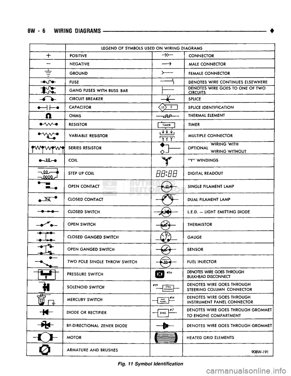
LEGEND
OF SYMBOLS
USED
ON
WIRING DIAGRAMS
+
POSITIVE
CONNECTOR
—
NEGATIVE
—>
MALE
CONNECTOR
_L_
GROUND
>
FEMALE CONNECTOR
FUSE
S DENOTES WIRE CONTINUES ELSEWHERE
GANG
FUSES
WITH
BUSS
BAR
DENOTES WIRE GOES
TO
ONE
OF TWO
CIRCUITS
CIRCUIT
BREAKER
SPLICE
CAPACITOR
<3>2
i
SPLICE
IDENTIFICATION
A
OHMS
cftP—
THERMAL ELEMENT
RESISTOR
| TIMER
|
TIMER
VARIABLE
RESISTOR
1
^ ^ ^ |
'YY Y1
MULTIPLE CONNECTOR
SERIES
RESISTOR
o-l
WIRING
WITH
OPTIONAL WIRING
WITHOUT
COIL Y "Y" WINDINGS
—o
STEP
UP COIL
BB-BB
DIGITAL READOUT
OPEN CONTACT
-0-
SINGLE
FILAMENT LAMP
M
K #
CLOSED
CONTACT
-(5-DUAL FILAMENT LAMP
CLOSED
SWITCH
LE.D.
-
LIGHT
EMITTING
DIODE
OPEN SWITCH —^— THERMISTOR
CLOSED
GANGED SWITCH
GAUGE
mi OPEN GANGED SWITCH
SENSOR
TWO POLE SINGLE THROW SWITCH FUEL INJECTOR
PRESSURE
SWITCH
E
|
#36
DENOTES WIRE
GOES
THROUGH
BULKHEAD DISCONNECT
3i
SOLENOID SWITCH
#" STRG
COLUMN DENOTES WIRE GOES THROUGH
STEERING
COLUMN CONNECTOR
frt
MERCURY
SWITCH
| PANEL
J
DENOTES WIRE GOES THROUGH
INSTRUMENT PANEL CONNECTOR
H«- DIODE
OR
RECTIFIER
j
ENG |
DENOTES WIRE GOES THROUGH GROMMET
TO ENGINE COMPARTMENT
BY-DIRECTIONAL ZENER DIODE DENOTES WIRE GOES THROUGH GROMMET
-o-
MOTOR
HEATED GRID ELEMENTS
0 ARMATURE AND BRUSHES
908W-191
Fig.
11
Symbol
identification