1993 DODGE TRUCK sensor
[x] Cancel search: sensorPage 499 of 1502
CRANKSHAFT
POSITION
SENSOR
TO CRANKSHAFT POSITION
(SEE
VIEW
X)
VEHICLE
SPEED
SENSOR
CONVERTER
CLUTCH
SOLENOID
TO
VEHICLE SPEED SENSOR BEYOND THIS POINT
SEE MAIN VIEW
TO HEATED OXYGEN SENSOR
(SEE VIEW X)
VIEW
A
4X4 TRANSFER
CASE
(TYPICAL)
VEHICLE
SPEED
SENSOR
1 >
a
so
>
w
J938W-102
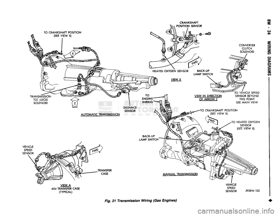
Fig. 21 Transmission Wiring (Gas Engines) 2
Page 501 of 1502
FUEL
INJECTOR
#6
FUEL
INJECTOR
#4
FUEL
INJECTOR
#2
BEYOND
THIS
POINT
SEE
VIEW
Z
EGR
SOLENOID/
TRANSDUCER
ASSEMBLY
A/C
COMPRESSOR
CLUTCH
GENERATOR
GROUND
POWER
STEERING
PUMP
AAAP
SENSOR
THROTTLE
EVAP/
POSITION
PURGE
(SENSOR)
SOLENOID IDLE
AIR
CONTROL MOTOR
TO
A/C
COMPRESSOR
CLUTCH
DISTRIBUTOR
IGNITION
COIL
ENGINE
COOLANT
TEMPERATURE
ENGINE
COOLANT
SENSOR
(PCM)
TEMPERATURE
SENSOR
(GAUGE)
ENGINE
OIL
PRESSURE
SENDING
UNIT/
SWITCH
DISTRIBUTOR
CONNER ,NJECTOR#1
INJECTOR
#3
VIEW
IN
DIRECTION OF ARROW
1
FUEL
INJECTOR
#5
TO
'TRANSMISSION
WIRING
J938W-85 INS
m
a
o
>
o
>
2
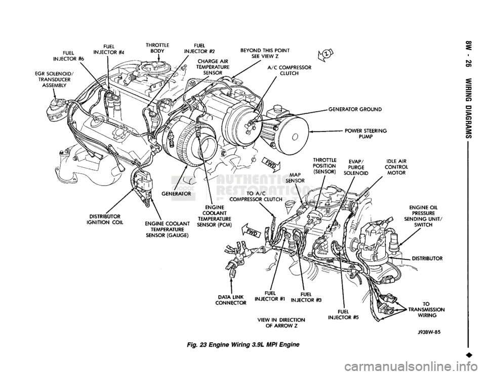
m Fig. 23 Engine
Wiring
3.9L MPI Engine
Page 502 of 1502
FUEL
INJECTOR
#8
FUEL
INJECTOR #4 FUEL
INJECTOR
#2
EGR
SOLENOID/
TRANSDUCER
DISTRIBUTOR
IGNITION
COIL
THROTTLE
BODY
CHARGE
AIR
TEMPERATURE
SENSOR
BEYOND
THIS
POINT
SEE
VIEW,
Z
TO
A/C
COMPRESSOR
CLUTCH ^DISTRIBUTOR
GENERATOR
GROUND
POWER
STEERING
PUMP ENGINE
OIL
PRESSURE
SENDING
UNIT/SWITCH
VIEW
IN
DIRECTION OF ARROW
Y
TO TRANSMISSION WIRING
THROTTLE
POSITION
(SENSOR)
IDLE AIR
CONTROL MOTOR
GENERATOR
ENGINE COOLANT
TEMPERATURE
SENSOR
(PCM)
ENGINE
COOLANT
TEMPERATURE
SENSOR
(GAUGE)
MAP
SENSOR
FUEL
INJECTOR
#3
EVAP/PURGE
SOLENOID
FUEL
INJECTOR #7
FUEL
INJECTOR.
#5
FUEL
INJECTOR
#1
A/C
CLUTCH VIEW
IN
DIRECTION
OF ARROW
Z
J938W-86
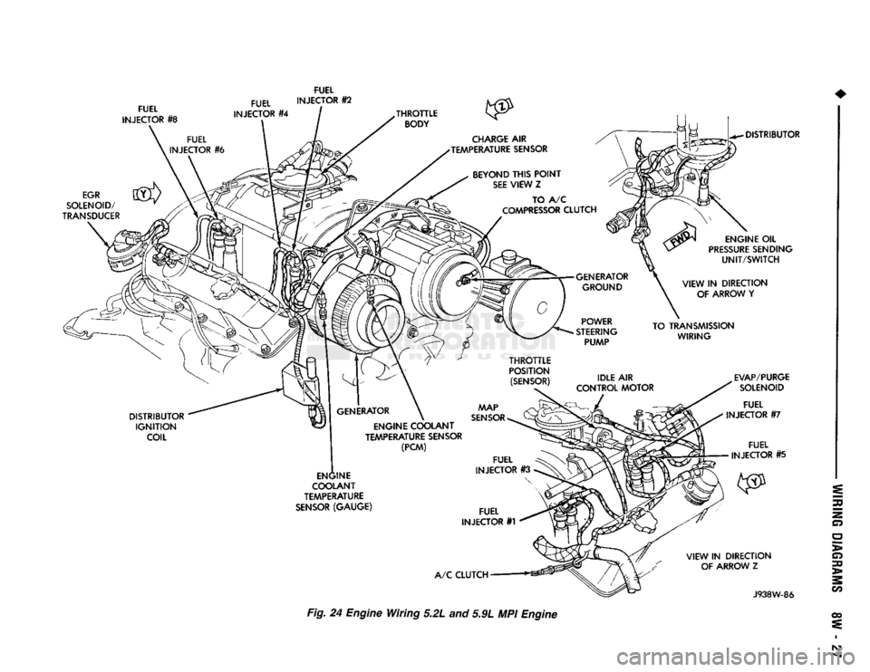
Fig.
24 Engine Wiring 5.2L and 5.9L MPI Engine o
>
30
>
2
w
oo !\3
Page 512 of 1502
WIRING
DIAGRAMS
8W
- 37
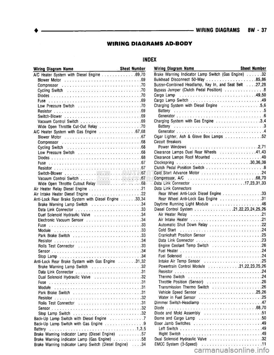
WIRING DIAGRAMS AD-BODY
INDEX
Wiring Diagram Name Sheet Number
A/C
Heater System
with
Diesel Engine ............ .69,70 Blower Motor
. .69
Compressor
.70
Cycling Switch
.70
Diodes
70
Fuse
69
Low Pressure Switch
70
Resistor
. 69
Switch-Blower
. 69
Vacuum
Control
Switch
.69
Wide Open
Throttle
Cut-Out Relay
70
A/C
Heater System
with Gas
Engine .67,68 Blower Motor
.67
Compressor
.68
Cycling Switch
68
Low Pressure Switch
.68
Diodes
. .68
Fuse
. .67
Resistor
67
Switch-Blower
67
Vacuum
Control
Switch
.67
Wide Open
Throttle
Cutout Relay
68
Air Heater Relay Diesel Engine
.21
Air
Intake
Heater Diesel Engine
22
Anti-Lock Rear Brake System
with
Diesel Engine
.....
.33,34 Brake Warning Lamp Switch
34
Data Link Connector
33
Duel Solenoid Hydraulic Valve
34
Electronic Vacuum
Sensor
.34
Fuse
33
Module
.33
Park
Brake Switch
.33
Resistor
34
Rolls
Test Connector
33
Sensor
34
Stop
Lamp
34
Anti-Lock Rear Brake System
with Gas
Engine .31,32 Brake Warning Lamp Switch
.32
Data Link Connector
. .31
Dual Solenoid Hydraulic Valve
32
Fuse
31
Module
31
Park
Brake Switch
.31
Resistor
32
Rolls
Test Connector
31
Sensor
32
Stop
Lamp Switch
32
Back-Up
Lamp Switch
with
Diesel Engine
.7
Back-Up
Lamp Switch
with Gas
Engine
.9
Battery
.1,3,5
Brake Warning
Indicator
Lamp (Diesel Engine)
.57
Brake Warning
Indicator
Lamp
(Gas
Engine)
58
Brake Warning
Indicator
Lamp Switch (Diesel Engine)
. . . .34
Wiring Diagram Name Sheet Number
Brake Warning
Indicator
Lamp Switch
(Gas
Engine)
32
Bulkhead Disconnect 50-Way .85,86
Buzzer-Combined Headlamp,
Key In, and
Seat
Belt
. . .
.27,28
Bypass
Jumper
(Clutch
Pedal Position)
8
Cargo
Lamp .49,50
Cargo
Lamp Switch
49
Charging System
with
Diesel Engine ..............
.5,6
Battery
5
Generator
. .6
Charging System
with
Gas Engine
.3,4
Battery
3
Generator
, . .4
Cigar
Lighter,
Ash &
Glove
Box
Lamps
52
Circuit
Breakers Power Windows
2,71
Clearance Lamps Duel Rear Wheels
.
.41,43 Clearance Lamps Roof Mounted
40
Clockspring 30,36,38
Clutch Pedal Position Switch
.8
Cold
Start
Advance Motor
24
Compressor,
A/C
68,70 Data Link Connector 17,23,31,33
Data Link Connectors
Rear
Wheel Anti-Lock Diesel Engine
.33
Rear
Wheel Anti-Lock Gas Engine
31
Daytime Running
Light
Module
46
Diesel
Control
System .21,22,23,24,25,26
Air Heater Relay
. .21
Air
Intake
Heater
21
Automatic
Shut Down Relay
22
Cold
Start
24
Crankshaft Position
Sensor
. .25
Data Link Connector
. .23
Engine
Coolant Temp Switch
.26
Fuel Heater
24
Fuel Solenoid
24
Intake
Air
Temp
Sensor
25
Powertrain
Control
Module 21,22,23,25,26
Resistor
.24
Thermo Switch
24
Throttle
Position (Sensor)
26
Transmission Thermo Switch
. . .26
Vehicle Speed
Sensor
25,26 Water
in
Fuel
Sensor
.25
Dimmer Switch-Headlamp
. .47
Diode 68,70
Diode
and
Mold Assembly
51
Dome
and
Cargo Lamp
50
Door
Jamb Switches
49
Left
Switch
.49
Right Switch
49
Dual Solenoid Hydraulic Valve
.32
EMCC
System (3-Speed)
. .11
Page 513 of 1502
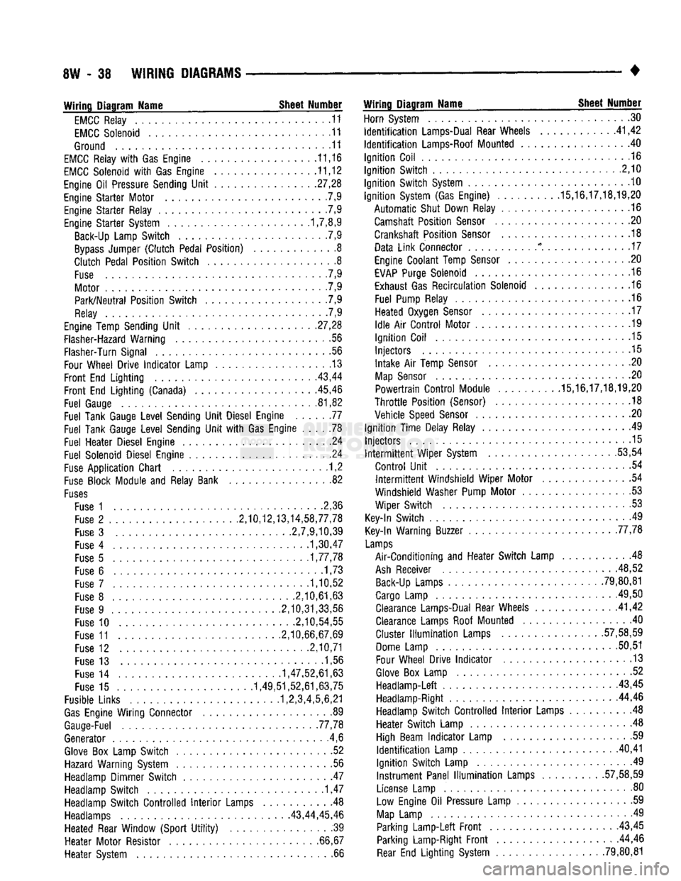
8W
- 38
WIRING
DIAGRAMS
• Wiring Diagram Name Sheet Number
EMCC
Relay
11
EMCC
Solenoid
11
Ground
11
EMCC
Relay
with Gas
Engine
11,16
EMCC
Solenoid
with Gas
Engine
11,12
Engine
Oil
Pressure Sending
Unit
.27,28
Engine
Starter
Motor
7,9
Engine
Starter
Relay
.7,9
Engine
Starter
System 1,7,8,9 Back-Up Lamp
Switch
.7,9
Bypass
Jumper
(Clutch
Pedal
Position)
8
Clutch
Pedal
Position
Switch
8
Fuse
. 7,9
Motor
7,9
Park/Neutral
Position
Switch
. .7,9
Relay
7,9
Engine Temp Sending
Unit
.
.27,28
Flasher-Hazard Warning
.56
Flasher-Turn Signal
56
Four Wheel
Drive
Indicator
Lamp
13
Front
End
Lighting
. .
.43,44
Front
End
Lighting
(Canada) 45,46
Fuel
Gauge
81,82
Fuel
Tank Gauge
Level
Sending
Unit
Diesel Engine
77
Fuel
Tank Gauge
Level
Sending
Unit
with Gas
Engine
78
Fuel
Heater
Diesel Engine
24
Fuel
Solenoid Diesel Engine
.24
Fuse
Application
Chart
1,2
Fuse
Block Module
and
Relay Bank
82
Fuses
Fuse
1 2,36
Fuse
2
.........
2,10,12,13,14,58,77,78
Fuse
3
2,7,9,10,39
Fuse
4
1,30,47
Fuse
5
1,77,78
Fuse
6
......
.1,73
Fuse
7
1,10,52
Fuse
8
.2,10,61,63
Fuse
9
.2,10,31,33,56
Fuse
10
.2,10,54,55
Fuse
11
2,10,66,67,69
Fuse
12
2,10,71
Fuse
13 1,56
Fuse
14
1,47,52,61,63
Fuse
15
1,49,51,52,61,63,75
Fusible Links 1,2,3,4,5,6,21
Gas
Engine
Wiring
Connector
89
Gauge-Fuel .77,78
Generator
.4,6
Glove
Box
Lamp
Switch
52
Hazard Warning System
. .56
Headlamp Dimmer
Switch
47
Headlamp
Switch
1,47
Headlamp
Switch
Controlled
Interior
Lamps
Headlamps 43,44,
Heated
Rear Window
(Sport
Utility)
Heater
Motor
Resistor
Heater
System Wiring Diagram Name Sheet Number
Horn System
30
Identification
Lamps-Dual Rear Wheels
41,42
Identification
Lamps-Roof Mounted
. 40
Ignition
Coil
.16
Ignition
Switch
.2,10
Ignition
Switch
System
10
Ignition
System (Gas Engine)
.........
.15,16,17,18,19,20
Automatic
Shut Down Relay
.16
Camshaft
Position
Sensor
20
Crankshaft
Position
Sensor
.18
Data
Link
Connector
* . . .17
Engine Coolant Temp
Sensor
20
EVAP
Purge Solenoid
16
Exhaust Gas
Recirculation
Solenoid
16
Fuel
Pump Relay
.16
Heated
Oxygen
Sensor
. . . 17
Idle
Air
Control
Motor
.19
Ignition
Coil
.15
Injectors
.15
Intake
Air
Temp
Sensor
. .20
Map
Sensor
. .20
Powertrain
Control
Module .15,16,17,18,19,20
Throttle
Position
(Sensor)
.18
Vehicle
Speed
Sensor
.20
Ignition
Time
Delay Relay
49
Injectors
.15 Intermittent
Wiper
System .53,54
Control
Unit
.54 Intermittent
Windshield
Wiper
Motor
54
Windshield
Washer Pump
Motor
53
Wiper
Switch
53
Key-In
Switch
49
Key-In Warning Buzzer 77,78
Lamps
Air-Conditioning
and
Heater
Switch
Lamp
48
Ash
Receiver .48,52 Back-Up Lamps
......
79,80,81
Cargo Lamp
.
.49,50 Clearance Lamps-Dual Rear Wheels .41,42
Clearance Lamps Roof Mounted
.40
Cluster
Illumination
Lamps
.
.57,58,59
Dome Lamp
50,51
Four Wheel
Drive
Indicator
.13
Glove
Box
Lamp
52
Headlamp-Left
43,45 Headlamp-Right 44,46
Headlamp
Switch
Controlled
Interior
Lamps
. 48
Heater
Switch
Lamp
.48
High Beam
Indicator
Lamp
.59
Identification
Lamp
.
.40,41
Ignition
Switch
Lamp
.49
Instrument
Panel
Illumination
Lamps
.
.57,58,59
License Lamp
. . . 80
.
.48 Low
Engine
Oil
Pressure Lamp
59
45,46
Map
Lamp
49
.
.39
Parking
Lamp-Left
Front
43,45
66,67 Parking Lamp-Right
Front
44,46 .
.66
Rear
End
Lighting
System .79,80,81
Page 514 of 1502
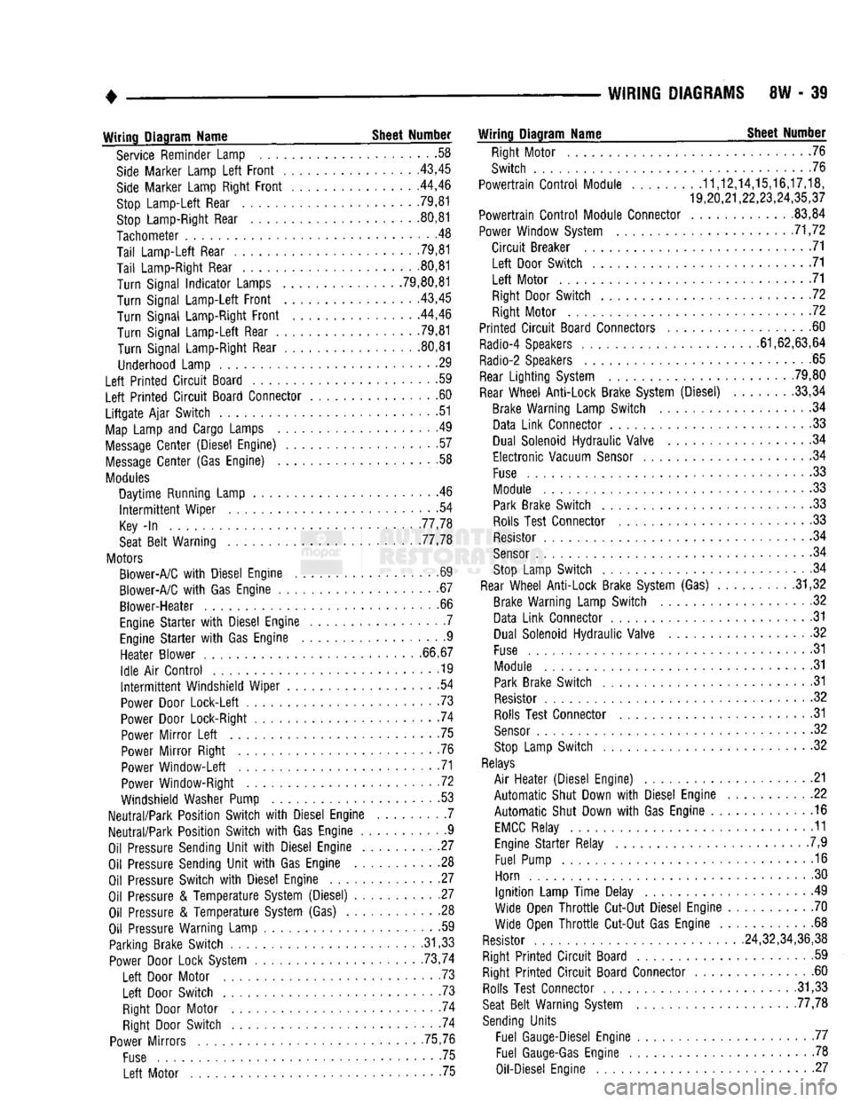
WIRING
DIAGRAMS
8W - 39
Wiring
Diagram
Name
Sheet
Number
Service Reminder Lamp .58
Side
Marker Lamp
Left
Front
43,45
Side
Marker Lamp Right
Front
. .44,46
Stop
Lamp-Left
Rear 79,81 Stop Lamp-Right Rear 80,81
Tachometer
.48
Tail
Lamp-Left
Rear .79,81
Tail
Lamp-Right Rear 80,81
Turn
Signal
Indicator
Lamps .79,80,81
Turn
Signal
Lamp-Left
Front
43,45
Turn
Signal Lamp-Right
Front
44,46
Turn
Signal
Lamp-Left
Rear .79,81
Turn
Signal Lamp-Right Rear 80,81
Underhood Lamp 29
Left
Printed
Circuit
Board .59
Left
Printed
Circuit
Board Connector 60
Liftgate
Ajar
Switch
51
Map
Lamp and Cargo Lamps .49
Message
Center
(Diesel Engine) 57
Message
Center
(Gas Engine) .58
Modules
Daytime
Running Lamp . .46
Intermittent
Wiper
.54
Key
-In
77,78
Seat
Belt
Warning 77,78
Motors Blower-A/C
with
Diesel Engine .69
Blower-A/C
with
Gas Engine 67
Blower-Heater
.66
Engine
Starter
with
Diesel Engine . .7 Engine
Starter
with
Gas Engine 9
Heater
Blower
66,67
Idle
Air
Control
............... ........
.19
Intermittent
Windshield
Wiper
54
Power Door
Lock-Left
.73
Power Door Lock-Right 74
Power
Mirror
Left
75
Power
Mirror
Right .76 Power
Window-Left
71
Power Window-Right .72
Windshield Washer Pump 53
Neutral/Park
Position
Switch
with
Diesel Engine 7
Neutral/Park
Position
Switch
with
Gas Engine 9
Oil Pressure Sending
Unit
with
Diesel Engine 27
Oil Pressure Sending
Unit
with
Gas Engine 28 Oil Pressure
Switch
with
Diesel Engine 27
Oil Pressure &
Temperature
System (Diesel) 27 Oil Pressure &
Temperature
System (Gas) . 28
Oil Pressure Warning Lamp • -59 Parking Brake
Switch
.31,33 Power Door Lock System . . 73,74
Left
Door Motor . .73
Left
Door
Switch
. 73
Right Door Motor . -74 Right Door
Switch
74
Power
Mirrors
75,76
Fuse
75
Left
Motor 75
Wiring
Diagram
Name
Sheet
Number
Right Motor 76
Switch
76
Powertrain
Control
Module
........
.11,12,14,15,16,17,18,
19,20,21,22,23,24,35,37
Powertrain
Control
Module Connector .83,84
Power Window System 71,72
Circuit
Breaker 71
Left
Door
Switch
71
Left
Motor 71 Right Door
Switch
72
Right Motor 72
Printed
Circuit
Board Connectors 60
Radio-4 Speakers 61,62,63,64
Radio-2 Speakers 65
Rear
Lighting
System 79,80
Rear
Wheel
Anti-Lock
Brake System (Diesel) 33,34 Brake Warning Lamp
Switch
.34 Data
Link
Connector 33
Dual Solenoid
Hydraulic
Valve 34
Electronic
Vacuum
Sensor
34
Fuse
.33 Module 33 Park Brake
Switch
33
Rolls Test Connector .33 Resistor .34
Sensor
. .34 Stop Lamp
Switch
. .34
Rear
Wheel
Anti-Lock
Brake System (Gas) . .31,32 Brake Warning Lamp
Switch
.32
Data
Link
Connector .31 Dual Solenoid
Hydraulic
Valve 32
Fuse
31
Module 31 Park Brake
Switch
31
Resistor 32 Rolls Test Connector 31
Sensor
32
Stop Lamp
Switch
32
Relays
Air
Heater
(Diesel Engine) .21
Automatic
Shut Down
with
Diesel Engine 22
Automatic
Shut Down
with
Gas Engine 16
EMCC
Relay 11 Engine
Starter
Relay .7,9
Fuel Pump 16
Horn 30
Ignition
Lamp
Time
Delay 49
Wide Open
Throttle
Cut-Out Diesel Engine 70
Wide Open
Throttle
Cut-Out Gas Engine 68
Resistor 24,32,34,36,38
Right
Printed
Circuit
Board 59 Right
Printed
Circuit
Board Connector 60 Rolls Test Connector .31,33
Seat
Belt
Warning System 77,78
Sending
Units
Fuel Gauge-Diesel Engine 77 Fuel
Gauge-Gas
Engine 78
Oil-Diesel Engine 27
Page 515 of 1502
8W
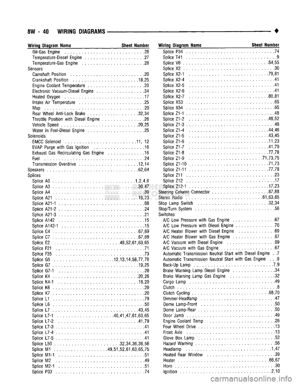
- 40
WIRING DIAGRAMS
Wiring Diagram Name Sheet Number
Oil-Gas
Engine
28
Temperature-Diesel Engine
. . . ., 27
Temperature-Gas Engine
. .28
Sensors
Camshaft Position
. . .20
Crankshaft Position
. .
.18,25
Engine
Coolant
Temperature
20
Electronic
Vacuum-Diesel Engine
. .34
Heated Oxygen
17
Intake
Air
Temperature
25
Map
20
Rear
Wheel Anti-Lock Brake 32,34
Throttle
Position
with
Diesel Engine
26
Vehicle Speed .20,25 Water
In
Fuel-Diesel Engine
25
Solenoids
EMCC
Solenoid
11, 12
EVAP
Purge
with
Gas
Ignition
.16
Exhaust
Gas
Recirculating
Gas Engine
.16
Fuel
.24
Transmission Overdrive
12,14
Speakers
62,64
Splices
Splice AO 1,2,4,6
Splice
A3
30,47
Splice
A4 39
Splice A21
16,23
Splice A21-1
. .68
Splice
A21-2 24
Splice A21-3
21
Splice A142
.15
Splice
A142-1 15
Splice
C4
.67,69
Splice
C7
.67,69
Splice
E2
.48,52,61,63,65
Splice F21
. , 71
Splice
F35 73
Splice
G5
12,13,14,58,77,78 Splice
G7
........... .19,25
Splice G7-1
. . .20
Splice
K4
20,26 Splice K4-1
.... ..... ; . 18,20
Splice
K6 , 20
Splice
K7 .20
Splice
L1 .79
Splice
L6 . .50
Splice
L7
43,45
Splice L7-1 40,41,47,61,63,65
Splice
L7-2
.41,79
Splice
L7-3 .41
Splice
L7-4 41
Splice
L7-5 .41
Splice
L50
......
.
........... .32,34,36,38,56
Splice
M1
49,51,52,61,63,65,75 Splice M1-1
51
Splice
M2 . .49
Splice M2-1
.51
Splice
P33 . 74
Wiring Diagram Name Sheet Number
Splice
P34 .... .74
Splice T41 ..............
.9
Splice
V6 . .
.54,55
Splice
X2 . .30
Splice X2-1
. . . .
.79,81
Splice X2-4
41
Splice X2-5
.41
Splice X2-6
.... .41
Splice X2-7
80,81
Splice X53
.65
Splice
X54
..........
. . 65
Splice Z1-1
.48
Splice Z1-2 48,52
Splice Z1-3
. . 48
Splice Z1-4
...
.44,46
Splice
Z1-5 ..... . . . .
-43,45
Splice Z1-6
11,23
Splice
Z1-7 .
.41,79
Splice Z1-8 77,78 Splice Z1-9
. .
............ .71,73,75
Splice Z1-10
. 71,73
Splice Z1-11 .77,78
Splice Z11
23
Splice
Z12 ' 17
Splice Z12-1
17,23
Steering Column Connector
.
87,88
Stereo Radio 61,63,65
Stop
Lamp Switch 32,34
Stop/Turn System
.56
Switches
A/C
Low
Pressure
with
Gas Engine
67
A/C
Low
Pressure
with
Diesel Engine
70
A/C
Heater Blower
with
Diesel Engine
69
A/C
Heater Blower
with
Gas Engine
67
A/C
Vacuum
with
Diesel Engine
69
A/C
Vacuum
with
Gas Engine
67
Automatic
Transmission
Neutral
Start
with
Diesel Engine
. .7
Automatic
Transmission
Neutral
Start
with
Gas Engine
. . .9
Back-Up
Lamp
.7,9
Brake Warning Lamp Diesel Engine
34
Brake Warning Lamp Gas Engine
. .32
Cargo
Lamp
49
Clutch
8
Clutch
Cycling
...
.68,70 Dimmer-Headlamp
47
Dome
Lamp-Front
. .50
Dome
Lamp-Rear
50
Door
Jamb
. 49
Engine
Coolant Temp
.26
Four
Wheel Drive
13
Front
Axle
13
Glove
Box
Lamp
. .52
Hazard Warning
.56
Headlamp
1,47
Heated Rear Window
39
Heater
. .
.66,67
Horn
.30
Ignition
2,10
Page 516 of 1502
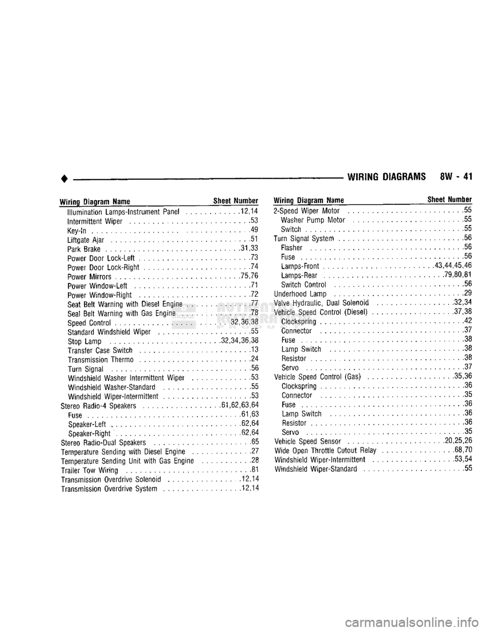
WIRING
DIAGRAMS
SW - 41
Wiring
Diagram Name _ Sheet Number
Illumination
Lamps-Instrument Panel ........... .12,14
Intermittent
Wiper ......................... .53
Key-In
. . . . . . . .49
Liftgate
Ajar
............................ .51
Park
Brake
.31,33
Power
Door Lock-Left ....................... .73
Power
Door Lock-Right .74
Power
Mirrors .75,76
Power
Window-Left 71
Power
Window-Right . .72
Seat
Belt
Warning
with
Diesel Engine 77
Seal
Belt
Warning
with
Gas Engine .78
Speed
Control
........... ,32,36,38
Standard
Windshield Wiper . .55
Stop
Lamp .32,34,36,38
Transfer
Case
Switch . 13
Transmission
Thermo ....................... .24
Turn Signal .56
Windshield Washer
Intermittent
Wiper . .53
Windshield Washer-Standard .55 Windshield
Wiper-Intermittent
53
Stereo
Radio-4 Speakers .61,62,63,64
Fuse
.61,63
Speaker-Left ......... ............ 62,64
Speaker-Right
. .62,64
Stereo
Radio-Dual Speakers .65
Temperature Sending
with
Diesel Engine . .27
Temperature Sending
Unit
with
Gas Engine .......... .28
Trailer
Tow Wiring 81
Transmission
Overdrive Solenoid ............... .12,14
Transmission
Overdrive System 12,14
Wiring
Diagram Name ^ Sheet Number
2-Speed
Wiper Motor 55
Washer
Pump
Motor
....................... .55
Switch 55
Turn
Signal
System
.......................... .56
Flasher
56
Fuse
.56
Lamps-Front
43,44,45,46
Lamps-Rear
. 79,80,81
Switch
Control
56
Underhood
Lamp 29
Valve
Hydraulic, Dual Solenoid .32,34
Vehicle
Speed
Control
(Diesel) .37,38
Clockspring 42 Connector .37
Fuse
................................. .38
Lamp
Switch . . .38
Resistor
.38
Servo
• .37
Vehicle
Speed
Control
(Gas) .35,36
Clockspring 36
Connector .35
Fuse
......... 36
Lamp
Switch .36
Resistor
.36
Servo
. 35
Vehicle
Speed
Sensor
.20,25,26 Wide Open
Throttle
Cutout Relay . .68,70
Windshield
Wiper-intermittent
...... ....... .53,54
Windshield Wiper-Standard 55