1993 DODGE TRUCK sensor
[x] Cancel search: sensorPage 161 of 1502
3
- 34
REAR SUSPENSION
AND
AXLE
• (4) Install the spring U-bolts and tighten the nuts
with the specified torque.
(5) Install the shock absorbers.
(6) Connect the parking brake cables.
(7) Connect the brake lines. Install the hubs and
brake drums. Adjust the wheel bearings (refer to Wheel Bearing Adjustment).
(8) Remove the block from the brake pedal. Bleed
and adjust the brakes.
(9) Connect the drive shaft to the pinion yoke with
the reference marks aligned. Tighten the U-joint clamp bolts to 21 N-m (16 ft. lbs./186 in. lbs.) torque.
(10) Install the rear wheels and tighten the lug
nuts with the specified torque (refer to Group 22,
Wheels And Tires). (11) Raise the rear of the vehicle, remove the sup
ports,
level the vehicle and position the supports. (12) Remove the fill hole plug from the differential
housing cover. Fill the differential housing to the correct level with MOPAR Hypoid Gear Lubricant, or
an equivalent product. Add 4 ounces of MOPAR Hypoid Gear Lubri
cant Additive for Trac-Lok equipped axles. (13) Install the fill hole plug. Remove the supports
and lower the vehicle. (14) Road test the vehicle to evaluate the results of
the repair.
DIFFERENTIAL
DISASSEMBLY
RE MO VA
L/DISA
SSEMBL Y
Remove the RWAL brake sensor
hold-down
bolt and pull the sensor from the differential
housing. The sensor must be removed to prevent damage when disassembling or assembling the differential components.
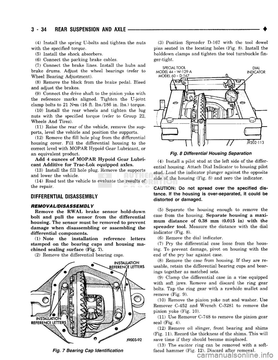
(1) Note the installation reference letters
stamped on the bearing caps and housing ma
chined sealing surface (Fig. 7). (2) Remove the differential bearing caps.
Fig.
7 Bearing Cap
identification
(3) Position Spreader D-167 with the tool dowel
pins seated in the locating holes (Fig. 8). Install the holddown clamps and tighten the tool turnbuckle fin
ger-tight.
SPECIAL TOOL DIAL
MODEL
44-W-129-A
INDICATOR
Fig.
8
Differential
Housing
Separation
(4) Install a pilot stud at the left side of the differ
ential housing. Attach Dial Indicator to housing pilot
stud. Load the indicator plunger against the opposite
side of the housing (Fig. 8) and zero the indicator.
CAUTION:
Do not
spread
over the specified
dis
tance. If the
housing
is over-separated, it
could
be distorted or
damaged.
(5) Separate the housing enough to remove the
case from the housing. Separate housing a maxi
mum distance of 0.38 mm (0.015 in) with the spreader tool. Measure the distance with the dial
indicator (Fig. 8).
(6) Remove the dial indicator. (7) Pry the differential case loose from the hous
ing. To prevent damage, pivot on housing with the
end of the pry bar against case.
(8) Remove the case from housing. If they are re
usable, retain the differential bearing cups and bear ings together as matched sets.
(9) Clamp the differential case in a vise equipped
with soft jaws. Remove and discard the ring gear
bolts.
Tap the ring gear with a rawhide mallet and
remove (Fig. 9).
(10) Remove the pinion yoke nut and washer. Use
Remover C-452 and Wrench C-3281 to remove the
pinion yoke (Fig. 10).
(11) Use Remover C-748 to remove the pinion gear
seal (Fig. 4).
(12) Remove oil slinger, front bearing and shims
(Fig. 11). Record the thickness of the shims. This will
save time if they should become misplaced.
(13) The excitor ring can be removed with a soft-
faced hammer (Fig. 12). Discard after removal.
Page 177 of 1502
3
- 50
REAR
SUSPENSION
AND
AXLE
• (6)
Install
the
RWAL brake
speed
sensor
and
cover
onto
the
axle
housing.
Tighten
the
sensor
to 24 Nsm (18 ft. lbs.)
torque.
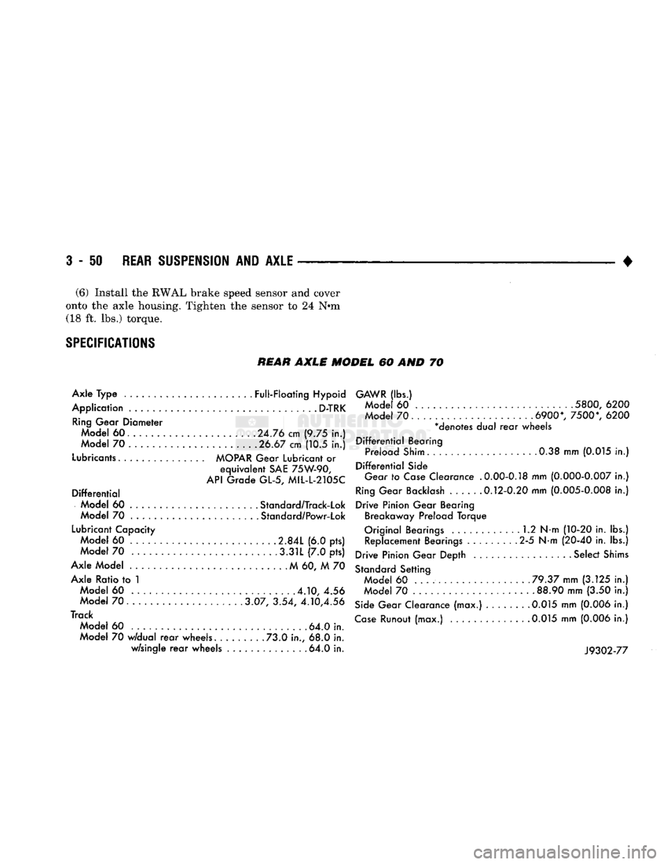
SPECIFICATIONS
REAR
AXLE MODEL 60 AND 70
Axle Type ......................
Full-Floating
Hypoid
Application
D-TRK
Ring
Gear Diameter Model 60. ............ .
.24.76
cm (9.75 in.)
Model 70 .................... .
.26.67
cm (10.5 in.)
Lubricants
MOPAR
Gear
Lubricant
or
equivalent
SAE
75W-90,
API
Grade GL-5, MIL-L-2105C
Differential
Model 60 .... . Standard/Track-Lok
Model 70 Standard/Powr-Lok
Lubricant
Capacity Model 60 .....
2.84L
(6.0 pts) Model 70 .3.31L (7.0 pts)
Axle Model M 60, M 70 Axle Ratio to 1 Model 60
.4.10,
4.56
Model
70......
3.07, 3.54,
4.10,4.56
Track Model 60 . 64.0 in.
Model 70
w/dual
rear
wheels. ....... .73.0 in., 68.0 in. w/single
rear
wheels ............. .64.0 in.
GAWR
(lbs.)
Mode
60
5800,
6200
Mode
70.
6900*,
7500*,
6200
*denotes dual
rear
wheels
Differential
Bearing Preload
Shim.
0.38 mm
(0.015
in.)
Differential
Side
Gear
to
Case
Clearance
.0.00-0.18
mm
(0.000-0.007
in.)
Ring
Gear
Backlash
.....
.0.12-0.20
mm
(0.005-0.008
in.)
Drive Pinion Gear Bearing Breakaway Preload Torque
Original Bearings 1.2 N-m
(10-20
in. lbs.) Replacement Bearings 2-5 N-m
(20-40
in. lbs.)
Drive Pinion Gear Depth ................. Select
Shims
Standard
Setting Model 60 ...
.79.37
mm
(3.125
in.)
Model 70 .
88.90
mm (3.50 in.)
Side
Gear Clearance (max.) 0.015 mm
(0.006
in.)
Case
Runout (max.)
.0.015
mm
(0.006
in.)
J9302-77
Page 186 of 1502
REAR
SUSPENSION
AND
AXLE
3 - 59
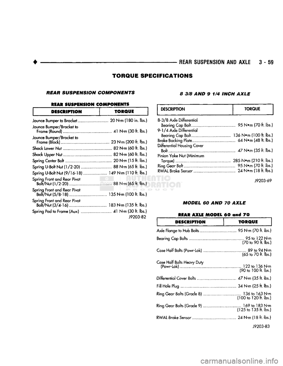
TORQUE
SPECIFICATIONS
REAR
SUSPENSION
COMPONENTS 8 3/8 AND 9 1/4 INCH
AXLE
REAR
SUSPENSION
COMPONENTS
DESCRIPTION
TORQUE
Jounce Bumper to Bracket 20 N-m (180 in. lbs.)
Jounce Bumper/Bracket to Frame (Round) 41 N-m (30 ft. lbs.)
Jounce Bumper/Bracket to Frame (Block)......... 23 N-m (200 ft. lbs.)
Shock
Lower Nut 82 N-m (60 ft. lbs.)
Shock
Upper Nut 82 N-m (60 ft. lbs.)
Spring
Center Bolt 20 N-m (15 ft. lbs.)
Spring
U-Bolt Nut
(1/2-20)
88 N-m (65 ft. lbs.)
Spring
U-Bolt Nut
(9/16-18)
149 N-m (110 ft. lbs.)
Spring
Front and Rear Pivot Bolt/Nut
(1/2-20)
88 N-m (65 ft. lbs.)
Spring
Front and Rear Pivot Bolt/Nut(5/8-18).... 135 N-m
(100ft.
lbs.)
Spring
Front and Rear Pivot Bolt/Nut
(3/4-16)
183 N-m (135 ft. lbs.)
Spring
Pad to Frame (Aux) 41 N-m (30 ft. lbs.)
J9203-82
DESCRIPTION
TORQUE
8-3/8 Axle
Differential
Bearing Cap Bolt
9-1/4 Axle
Differential
Bearing Cap Bolt
Brake
Backing
Plate ,
Differential
Housing
Cover
Bolt
Pinion Yoke Nut (Minimum Torque)
Ring
Gear Bolt...
RWAL
Brake
Sensor
95 N*m (70 ft. lbs.)
136
N*m(100
ft. lbs.)
... 64 N*m (48 ft. lbs.)
47 N*m (35 ft. lbs.;
285Ntti
(210 ft. lbs.)
... 95 N*m (70 ft. lbs.) ... 24 N*m (18 ft. lbs.)
J9203-69
MODEL
60 AND 70
AXLE
REAR
AXLE
MODEL
60 and 70
DESCRIPTION
TORQUE
Axle Flange to Hub Bolts. Bearing Cap Bolts 95 N-m (70 ft. lbs.)
... 95 to 122 N-m (70 to 90 ft. lbs.)
Case
Half
Bolts
(Powr-Lok) ..
Case
Half
Bolts
Heavy Duty (Powr-Lok)
Differential
Cover Bolts
Fill
Hole Plug
Ring
Gear
Bolts
(Grade 8)
Ring
Gear
Bolts
(Grade 9)
RWAL
Brake
Sensor
89 to 94 N-m
(65 to 70 ft. lbs.)
122 to 136 N-m
(90 to 100 ft. lbs.)
47 N-m (35 ft. lbs.) 34 N-m (25 ft. lbs.) 136 to 163 N-m
(100 to 120 ft. lbs.) 169 to 183 N-m
(125 to 135 ft. lbs.)
24 N-m (18 ft. lbs.)
J9203-83
Page 204 of 1502
TUBE ASSEMBLY MASTER
CYLINDER TO BRAKE
VALVE REAR (SECONDARY)
BRACKET
AND SHIELD
BRAKE
HOSE AND RWAL
SENSOR
WIRING LET.
TORQUE
LET. POUNDS NEWTON
METRES
x!^ 145 IN.
16
XX 35 FT.
47
170 IN. 19
100 IN.
11
125
IN.
14
BRAKE
VALVE TUBE
TO RIGHT FRONT
BRAKE
HOSE
VIEW IN DIRECTION OF ARROW A
SCREW
<§>
GASKET
8905-54
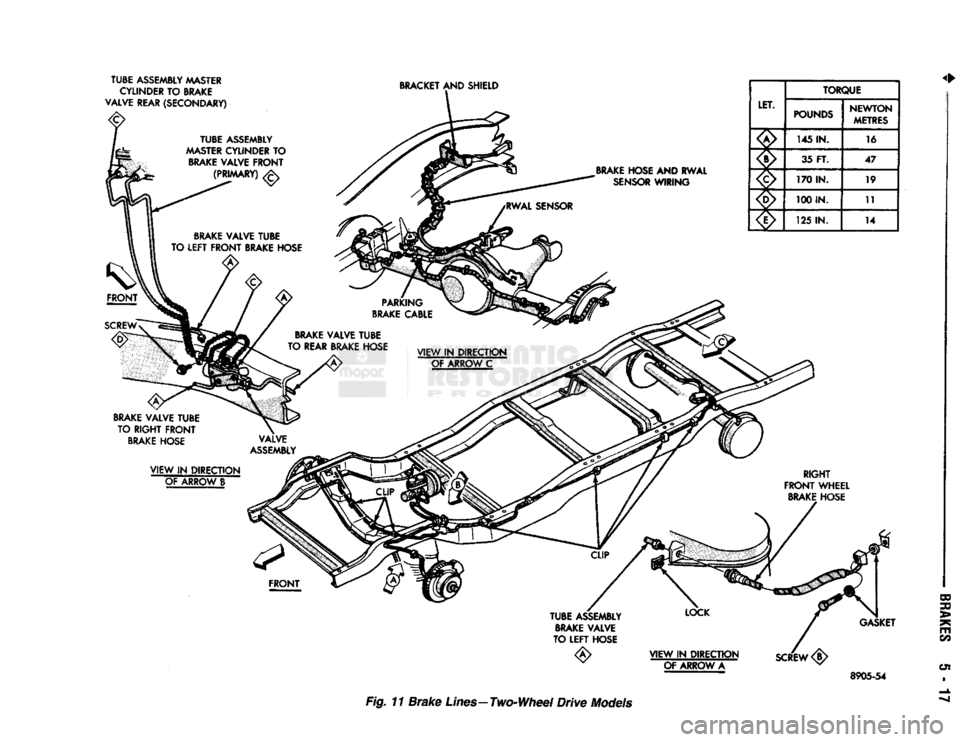
Fig. 11
Brake
Lines—Two-Wheel
Drive
Models
Page 210 of 1502
•
BRAKES
5 - 23
VACUUM PUMP OPERATION
Vacuum pump output is transmitted to the power
brake booster through a supply hose. The hose is con nected to an outlet port on the pump housing and to
the check valve in the power brake booster.
Pump output ranges from a minimum of 8.5 to 25
inches vacuum. The pump rotor and vanes are rotated by the pump
drive gear. The drive gear is operated by the cam
shaft gear. Booster vacuum level is monitored by a warning
switch (Fig. 2). The switch consists of a vacuum
chamber that measures vacuum level and a sensor in
circuit with the brake warning light. The vacuum chamber is connected to the booster
check valve by a vacuum supply hose. A wire har
ness connects the switch sensor to the brake warning
light. If booster vacuum falls below 8.5 inches for 8-10 seconds or more, the switch sensor completes
the circuit to the warning light causing it to illumi
nate.
VACUUM PUMP DIAGNOSIS
Vacuum pump diagnosis involves checking pump
output with a vacuum gauge. The low vacuum warn
ing switch can also be checked with a vacuum gauge.
Refer to the diagnosis procedure in this section. A standard vacuum gauge can be used to check
pump output when necessary. Simply disconnect the
pump supply hose and connect a vacuum gauge to
the outlet port for testing purposes. Vacuum should
hold steady in a range of approximately 8.5 to 25 inches at various engine speeds.
DIAGNOSING LOW VACUUM OUTPUT CONDITION A low booster vacuum condition or a faulty low
vacuum warning switch will cause the brake warn ing light to illuminate. If the light does go on and in
dicates the existence of a low vacuum condition,
check the vacuum pump, booster and warning switch
as follows:
(1) Check vacuum pump oil feed line. Verify that
line connections are secure and not leaking. If leak age is noted and pump is noisy, replace pump.
(2) Disconnect supply hose to booster. Connect vac
uum gauge to this hose and run engine at various
throttle openings. Output should range from 8.5 to 25 inches vacuum. If vacuum is consistently below
8.5 inches, problem is with vacuum hoses or pump
component. If output is within specified limits, con
tinue testing.
(3) Check booster operation as described in diagno
sis section. Replace check valve, vacuum hoses, or
booster if necessary. However, if booster operation is correct but warning light is still on, continue testing. (4) Disconnect vacuum hose at warning switch.
Plug hose and connect hand vacuum pump to switch. (5) Start and run engine.
(6) Apply 8.5 to 9 inches of vacuum to warning
switch and observe warning light. If light goes out,
switch vacuum hose is either loose or leaking. If
light remains on, leave engine running and continue
testing.
(7) Apply 20-25 inches vacuum to switch and ob
serve warning light operation. If light now goes out,
switch is at fault and should be replaced. If light re
mains on, continue testing.
(8) Reconnect vacuum hoses and replace original
warning switch with known good switch. Run engine and observe warning light operation. If light is now
off, old switch is faulty. If light remains on, problem
is in wiring between switch and warning light.
VACUUM-STEERING PUMP
ASSEMBLY
REMOVAL
(1) Disconnect battery negative cable.
(2) Position drain pan under power steering pump.
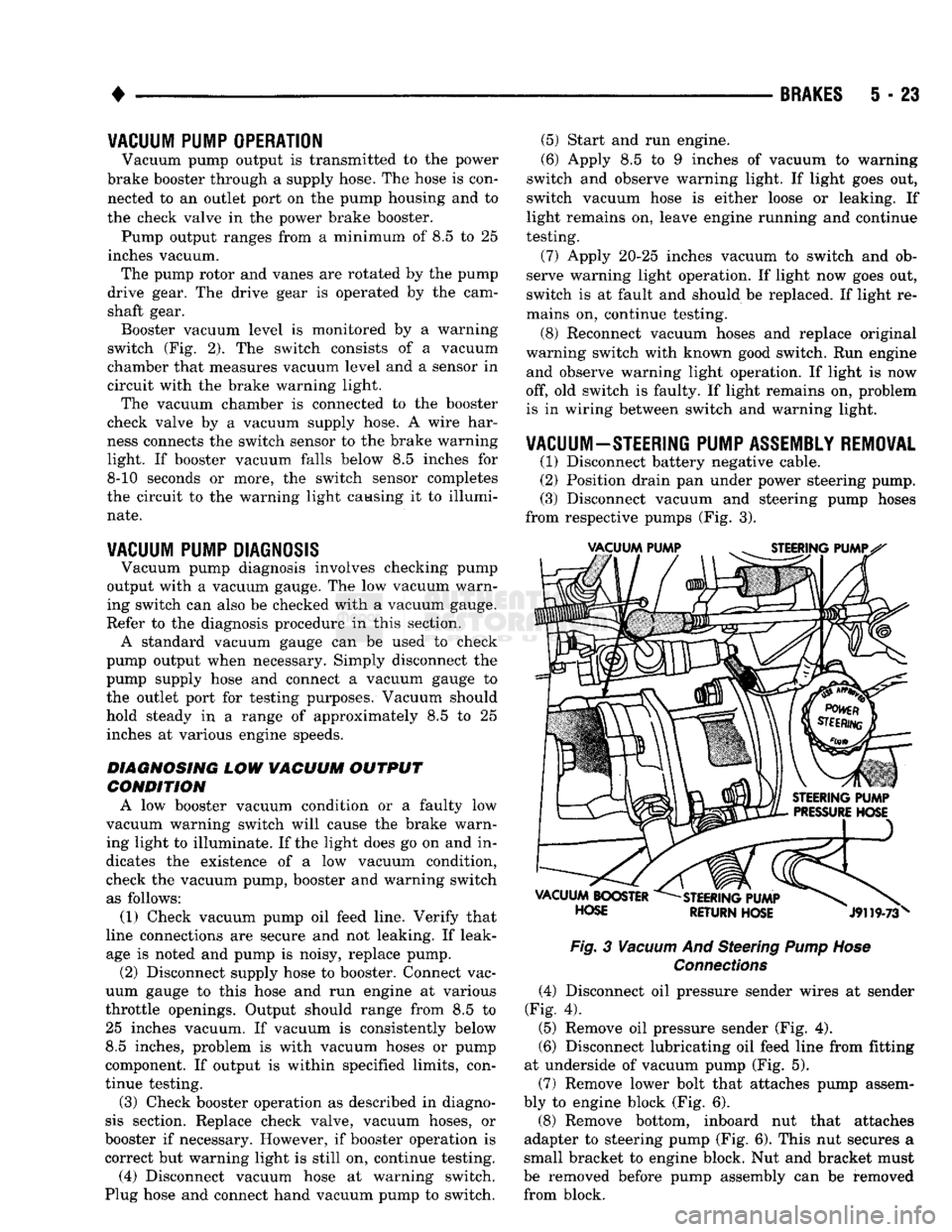
(3) Disconnect vacuum and steering pump hoses
from respective pumps (Fig. 3).
Fig.
3
Vacuum
And Steering
Pump Hose
Connections
(4) Disconnect oil pressure sender wires at sender
(Fig. 4).
(5) Remove oil pressure sender (Fig. 4).
(6) Disconnect lubricating oil feed line from fitting
at underside of vacuum pump (Fig. 5).
(7) Remove lower bolt that attaches pump assem
bly to engine block (Fig. 6).
(8) Remove bottom, inboard nut that attaches
adapter to steering pump (Fig. 6). This nut secures a
small bracket to engine block. Nut and bracket must
be removed before pump assembly can be removed from block.
Page 246 of 1502
•
BRAKES
5 - 59
REAR
WHEEL
ANTILOCK
(RWAL) BRAKES
page
Antilock
Component Service
63
Antilock
Service Diagnosis
62
Checking
Speed
Sensor
Air
Gap .............
64
Clearing
A
Fault
Code .....................
63
Electronic
Control
Module Replacement
........
64
Fault Code Capacity
62
Fault Code
Identification
62
page
General
Information
59
Hydraulic Valve Replacement
63
Speed
Sensor
Replacement
................
64
System
Components
......................
59
System
Fault
Codes
......................
62
System
Operation
61
GENERAL
INFORMATION
A rear wheel antilock brake system
is
standard
equipment
on all AD
models.
It is an
electronically operated system designed
to
retard rear wheel lockup
during periods
of
high wheel slip
and
deceleration.
Retarding lockup
is
accomplished
by
modulating
fluid pressure
to the
rear brake units. Rear brake fluid apply pressure
is
modulated
ac
cording
to
wheel speed, degree
of
wheel slip
and
rate
of deceleration.
A
sensor located
in the
rear axle
housing converts differential rotating speed into elec
tronic signals.
The
signals
are
transmitted
to the
electronic brake control module
for
processing.
The
control unit determines rate
of
deceleration
and
wheel slip from these signals.
SYSTEM
COMPONENTS
Basic system components include
an
electronic
brake control module,
a
hydraulic pressure control
valve,
a
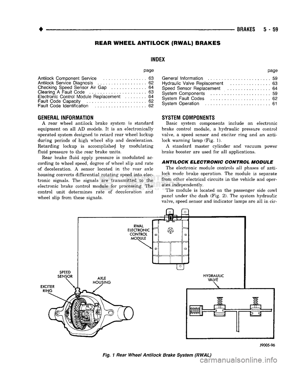
speed sensor
and
exciter ring
and an
anti- lock warning lamp (Fig.
1).
A standard master cylinder
and
vacuum power
brake booster
are
used
for all
applications.
ANTILOCK ELECTRONIC CONTROL MODULE
The electronic module controls
all
phases
of
anti-
lock mode brake operation.
The
module
is
separate
from other electrical circuits
in the
vehicle
and
oper ates independently.
The module
is
located
on the
passenger side cowl
panel under
the
dash
(Fig.
2).
The
system hydraulic
valve, speed sensor
and
indicator lamps
are all in cir-
SPEED
SENSOR
EXCITER RING j3l
a
RWAL
ELECTRONIC
CONTROL MODULE AXLE
HOUSING HYDRAULIC
VALVE
J9005-96
Fig.
1
Rear
Wheel
Antilock
Brake
System
(RWAL)
Page 247 of 1502
5
- 60
BRAKES
Fig.
2
Antilock
Electronic Control
Module
RWAL
HYDRAULIC
VALVE
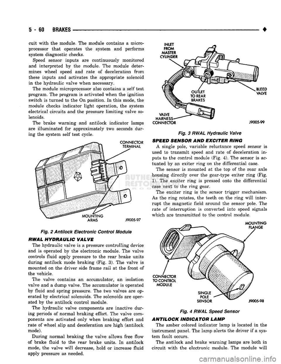
The hydraulic valve is a pressure controlling device
and is operated by the electronic module. The valve
controls fluid apply pressure to the rear brake units
during antilock mode braking (Fig. 3). The valve is
mounted on the driver side frame rail at the front of
the vehicle.
The valve contains an accumulator, an isolation
valve and a dump valve. The accumulator is operated
by fluid and spring pressure. The two valves are op erated by electrical solenoids. The solenoids are oper
ated by the antilock control module.
The hydraulic valve components are inactive dur
ing periods of normal braking effort. The valve com
ponents are activated only when braking effort and rate of wheel slip and deceleration are high (antilock
mode).
During normal braking the valve allows free flow
of brake fluid to the rear brake units. In antilock
mode, the valve will decrease, hold or increase fluid
apply pressure as needed. •
CONNECTOR
J9005-99
Fig. 3 RWAL Hydraulic Valve
SPEED
SENSOR
AND EXCITER RING
A single pole, variable reluctance speed sensor is
used to transmit speed and rate of deceleration in
puts to the control module (Fig. 4). The sensor is ac
tuated by an exiter ring on the differential case.
The sensor is mounted at the top of the rear axle
housing directly over the gear-type exiter ring (Fig.
1).
The exciter ring is pressed onto the differential
case next to the ring gear.
The exciter ring is the sensor trigger mechanism.
As the ring rotates, the teeth on the ring will inter
rupt the magnetic field around the sensor pole. The rate of interruption is converted into speed signals
which are transmitted to the control module.
Fig.
4
RWAL Speed Sensor
ANTILOCK INDICATOR LAMP The amber colored indicator lamp is located in the
instrument panel. The lamp alerts the driver if a sys
tem fault occurs.
The antilock and brake warning lamps are both in
circuit with the electronic module. The module will
cuit with the module. The module contains a micro
processor that operates the system and performs system diagnostic checks. Speed sensor inputs are continuously monitored
and interpreted by the module. The module deter
mines wheel speed and rate of deceleration from
these inputs and activates the appropriate solenoid in the hydraulic valve when necessary.
The module microprocessor also contains a self test
program. The program is activated when the ignition switch is turned to the On position. In this mode, the
module checks indicator light operation, the system
electrical circuits and the pressure limiting valve so
lenoids.
The brake warning and antilock indicator lamps
are illuminated for approximately two seconds dur
ing the system self test cycle.
Page 248 of 1502
•
BRAKES
5 - 61 cause the two lamps to illuminate or flash to alert
the driver that system operation is either normal or
that a fault has occurred.
SYSTEM
OPERATION
During light brake applications, rear wheel decel
eration and/or slip is not sufficient to activate the an
tilock system. Brake fluid apply pressure at the rear
wheels is normal. However, when braking effort, de gree of wheel slip and rate of deceleration approach
programmed limits, sensor inputs will cause the module to activate the system.
Normal
Braking
Mode
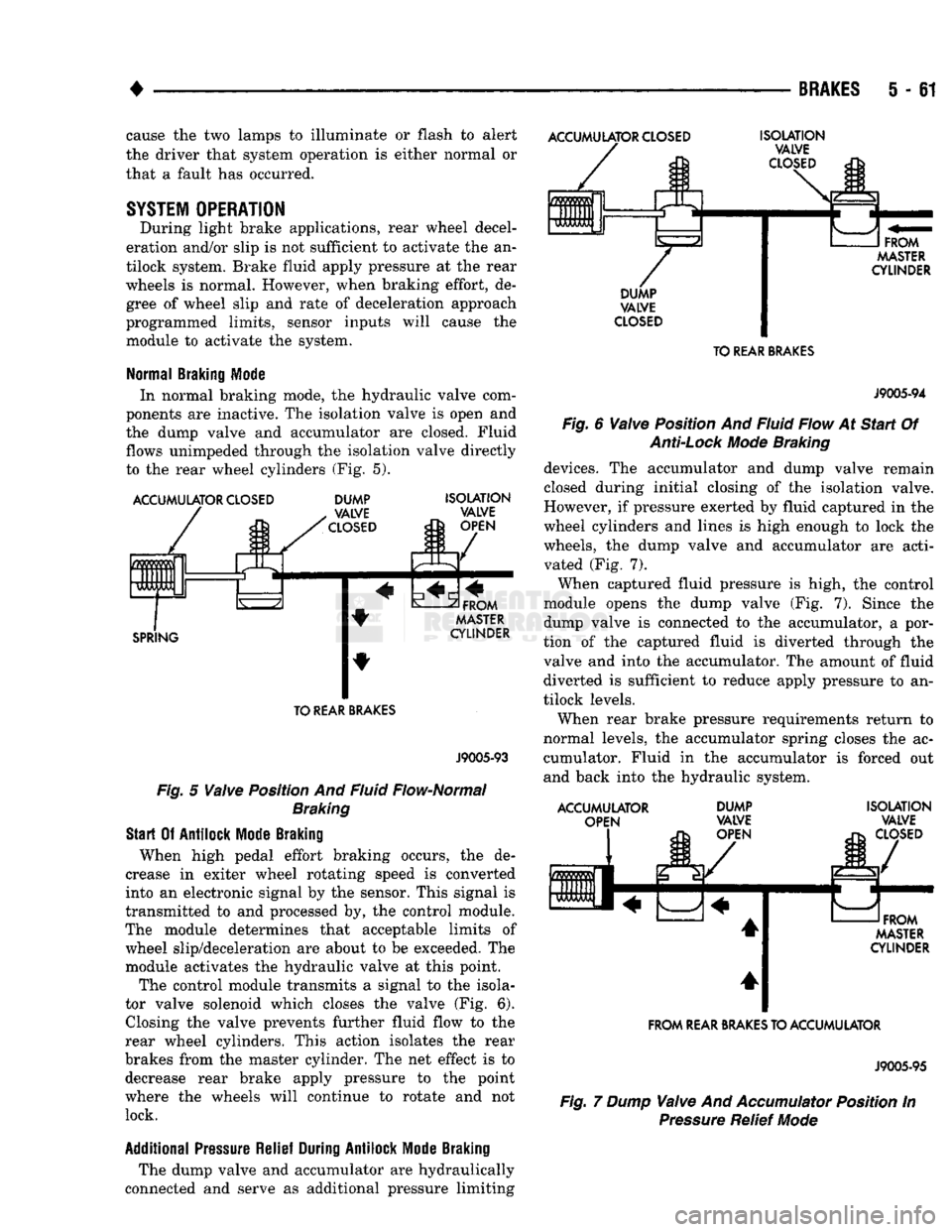
In normal braking mode, the hydraulic valve com
ponents are inactive. The isolation valve is open and
the dump valve and accumulator are closed. Fluid
flows unimpeded through the isolation valve directly
to the rear wheel cylinders (Fig. 5).
ACCUMULATOR
CLOSED
ACCUMULATOR
CLOSED
0 m
m
0 UUb Ft
L DUMP
VALVE
CLOSED
SPRING
ISOLATION
VALVE
OPEN
FROM
MASTER
CYLINDER TO
REAR
BRAKES
J9005-93
Fig.
5
Valve
Position And Fluid Flow-Normal
Braking
Start
Of
Antilock
Mode
Braking
When high pedal effort braking occurs, the de
crease in exiter wheel rotating speed is converted
into an electronic signal by the sensor. This signal is
transmitted to and processed by, the control module.
The module determines that acceptable limits of wheel slip/deceleration are about to be exceeded. The
module activates the hydraulic valve at this point.
The control module transmits a signal to the isola
tor valve solenoid which closes the valve (Fig. 6). Closing the valve prevents further fluid flow to the
rear wheel cylinders. This action isolates the rear
brakes from the master cylinder. The net effect is to decrease rear brake apply pressure to the point
where the wheels will continue to rotate and not lock.
Additional
Pressure
Relief
During
Antilock
Mode
Braking
The dump valve and accumulator are hydraulically
connected and serve as additional pressure limiting
ISOLATION
VALVE
CLOSED
FROM
MASTER
CYLINDER
DUMP
VALVE
CLOSED
TO
REAR
BRAKES
J9005-94
Fig.
6
Valve
Position And Fluid Flow At
Start
Of
Anti-Lock
Mode
Braking
devices. The accumulator and dump valve remain
closed during initial closing of the isolation valve.
However, if pressure exerted by fluid captured in the
wheel cylinders and lines is high enough to lock the
wheels, the dump valve and accumulator are acti vated (Fig. 7).
When captured fluid pressure is high, the control
module opens the dump valve (Fig. 7). Since the
dump valve is connected to the accumulator, a por
tion of the captured fluid is diverted through the
valve and into the accumulator. The amount of fluid diverted is sufficient to reduce apply pressure to an
tilock levels.
When rear brake pressure requirements return to
normal levels, the accumulator spring closes the ac cumulator. Fluid in the accumulator is forced out
and back into the hydraulic system.
ACCUMULATOR OPEN DUMP
VALVE
OPEN ISOLATION
VALVE
CLOSED
FROM
MASTER
CYLINDER
FROM
REAR
BRAKES
TO ACCUMULATOR
J9005-95
Fig.
7 Dump
Valve
And
Accumulator
Position In
Pressure
Relief
Mode