1993 DODGE TRUCK sensor
[x] Cancel search: sensorPage 1106 of 1502
•
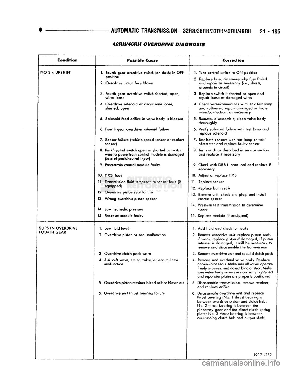
AUTOMATIC
TRANSMISSION—32RH/36RH/37RH/42RH/46RH
21-105 Condition
Possible
Co
use
Correction
NO
3-4 UPSHIFT
1.
Fourth
gear overdrive
switch
(on dash) in
OFF
1.
Turn control
switch
to ON position
2.
position
Overdrive
circuit
fuse
blown
2. Replace fuse; determine why fuse failed
and
repair as necessary
(i.e.,
shorts,
grounds
in
circuit)
3.
Fourth
gear
overdrive
switch
shorted, open,
wires
loose 3. Replace switch if shorted or open and
repair loose or damaged wires
4. Overdrive solenoid or circuit
wire
loose,
shorted, open 4. Check wires/connections
with
12V test lamp
and
voltmeter; repair damaged or loose
wires/connections as necessary
5. Solenoid
feed
orifice
in valve body is
blocked
5. Remove, disassemble, clean valve body
thoroughly
6.
Fourth
gear
overdrive
solenoid
failure
6. Verify solenoid
failure
with
test lamp and
replace solenoid
7.
Sensor
failure
(vehicle speed sensor or coolant
sensor)
7. Test both
sensors
with
test lamp or volt/
ohmmeter and replace
faulty
sensor
8. Park/neutral switch open or
shorted
or
switch
wire
to
powertrain
control
module is damaged
(loss
of park/neutral
input)
8. Test switch as described in service section
and
replace if necessary
9.
Powertrain
control module
faulty
9. Check
with
DRB II
scan
tool and replace if
necessary
10.
T.P.S.
fault
10. Adjust or replace
T.P.S.
11.
Transmission fluid
temperature
sensor
fault
(if equipped)
12. Overdrive piston seal
failure
13. Wrong
overdrive
piston
spacer
11.
Replace sensor
12. Replace both
seals
13. Remove unit, check end play, and install correct spacer
14.
Low
hydraulic pressure 14. Pressure test transmission to determine
cause
15. Set-reset module
faulty
15. Replace module (if equipped)
SUPS
IN
OVERDRIVE
FOURTH
GEAR
1.
2. Low
fluid
level
Overdrive piston or seal
malfunction
1.
Add fluid and check for leaks
2. Remove overdrive unit; replace piston
seals
if worn; replace piston if damaged, if piston
retainer
is damaged, it
will
be necessary to
remove and disassemble the transmission
3. Overdrive clutch pack
worn
3. Remove overdrive unit and rebuild clutch pack
4. 3-4
shift
valve,
timing
valve, or accumulator
malfunction
4. Remove and overhaul valve body. Replace
accumulator
seals.
Make sure all valves operate
freely
in bores, and do not bind or stick. Make
sure
valve body screws are correctly tightened
and
separator plates are properly positioned
5. Overdrive
piston
retainer
bleed
orifice
blown out 5. Disassemble transmission, remove
retainer,
and
replace orifice
6. Overdrive
unit
thrust
bearing
failure
6. Disassemble overdrive unit and replace
thrust bearing (No. 1 thrust bearing is between overdrive piston and clutch hub;
No.
2 thrust bearing is between the
planetary gear and the direct clutch spring plate; No. 3
thrust
bearing is between
overrunning clutch hub and output shaft)
J9321-252
42RH/46RH OVERDRIVE DIAGNOSIS
Page 1107 of 1502
21-106
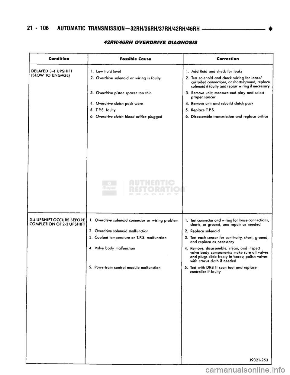
AUTOMATIC
TRANSMISSION—32RH/36RH/37RH/42RH/46RH
42RH/46RH OVERDRIVE DIAGNOSIS •
Condition
Possible
Cause
Correction
DELAYED
3-4
UPSHIFT
(SLOW
TO
ENGAGE)
1.
Low fluid
level
2. Overdrive solenoid or wiring is faulty
3.
Overdrive piston spacer too thin
4. Overdrive clutch pack worn
5.
T.P.S.
faulty
6. Overdrive clutch bleed orifice
plugged
1.
Add fluid and check for leaks
2. Test solenoid and check wiring for
loose/
corroded
connections,
or
shorts/ground;
replace
solenoid
if faulty and repiar wiring if
necessary
3.
Remove unit; measure end play and select proper spacer
4. Remove unit and rebuild clutch pack
5. Replace
T.P.S.
6.
Disassemble
transmission
and replace orifice
3-4
UPSHIFT
OCCURS
BEFORE
COMPLETION
OF 2-3
UPSHIFT
1.
Overdrive solenoid connector or wiring problem
2. Overdrive solenoid malfunction
3.
Coolant temperature or
T.P.S.
malfunction
4. Valve body malfunction
5. Powertrain control module malfunction
1.
Test connector and wiring for
loose
connections,
shorts,
or
ground,
and repair as needed
2. Replace solenoid
3.
Test each
sensor
for continuity, short,
ground,
and
replace as necessary
4. Remove,
disassemble,
clean, and inspect
valve
body components; make sure all valves
and
plugs
slide
freely
in bores; polish valves
with
crocus
cloth if needed
3. Test
with
DRB II
scan
tool and replace controller if faulty
J9321-253
Page 1108 of 1502
+
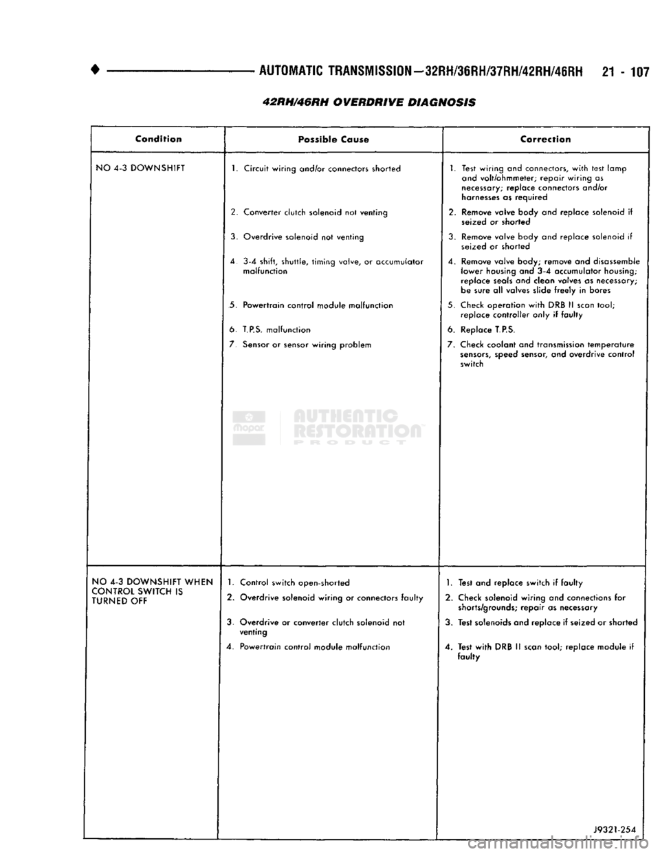
AUTOMATIC
TRANSMISSION-32RH/36RH/37RH/42RH/46RH
21-107
42RH/46RH
OVERDRIVE
DIAGNOSIS
Condition
Possible
Cause
Correction
NO
4-3 DOWNSHIFT 1. Circuit wiring and/or connectors shorted
2. Converter clutch solenoid not venting
3. Overdrive solenoid not venting
4.
3-4 shift, shuttle, timing
valve,
or accumulator malfunction
5. Powertrain control module malfunction
6.
T.P.S.
malfunction
7.
Sensor
or sensor wiring problem 1. Test wiring and connectors,
with
test lamp
and
volt/ohmmeter; repair wiring as
necessary;
replace connectors and/or
harnesses
as required
2. Remove valve body and replace solenoid if seized or shorted
3. Remove valve body and replace solenoid if seized or shorted
4. Remove valve body; remove and disassemble lower housing and 3-4 accumulator
housing;
replace
seals
and clean valves as necessary;
be sure all valves slide
freely
in bores
5. Check operation
with
DRB II
scan
tool; replace controller only if faulty
6. Replace
T.P.S.
7. Check coolant and transmission
temperature
sensors,
speed sensor, and overdrive control
switch
NO
4-3 DOWNSHIFT WHEN
CONTROL
SWITCH
IS
TURNED
OFF 1. Control switch open-shorted
2. Overdrive solenoid wiring or connectors faulty
3. Overdrive or converter clutch solenoid not venting
4. Powertrain control module malfunction
1.
Test and replace switch if faulty
2. Check solenoid wiring and connections for
shorts/grounds;
repair as necessary
3. Test solenoids and replace if seized or shorted
4. Test
with
DRB II
scan
tool; replace module if faulty
J9321-254
Page 1135 of 1502
21
- 134
IN-WEHiCLE SER¥iCE-32RH/3IRH/37RH/42RH/46RH
• • On 36RH/37RH746RH, back off adjusting screw
two turns. (6) Hold adjusting screw in place with backup
wrench. Then tighten locknut to 34 N*m (25 ft. lbs.) torque.
(7) Position new gasket on oil pan and install pan
on transmission. Tighten pan bolts to 17 N»m (13 ft.
lbs.) torque.
(8) Lower vehicle and refill transmission with Mo
par ATF Plus, type 7176, or Dexron II™ fluid.
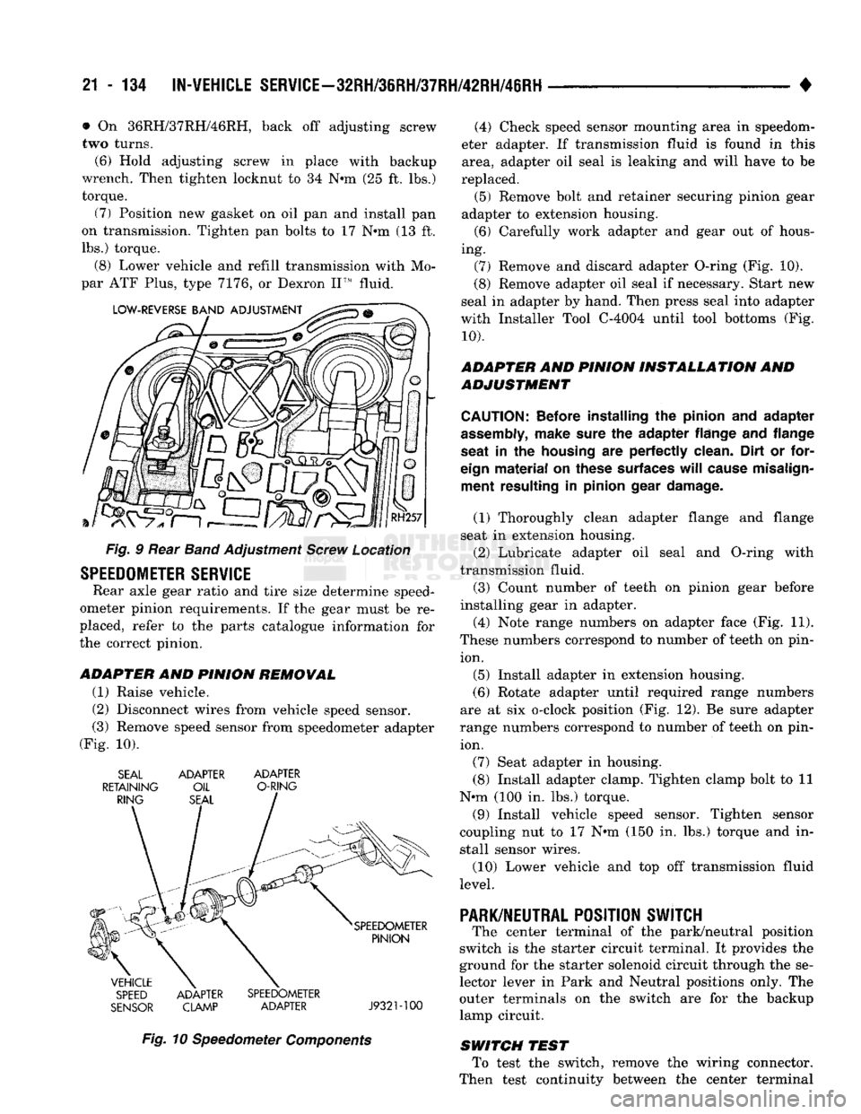
Fig. § Rear Band Adjustment Screw Location
SPEEDOMETER
SERVICE
Rear axle gear ratio and tire size determine speed
ometer pinion requirements. If the gear must be re
placed, refer to the parts catalogue information for
the correct pinion.
ADAPTER
AND
PINION REMOWAL
(1) Raise vehicle.
(2) Disconnect wires from vehicle speed sensor.
(3) Remove speed sensor from speedometer adapter
(Fig. 10). SEAL ADAPTER ADAPTER
RETAINING OIL O-RING
SPEED ADAPTER SPEEDOMETER
SENSOR CLAMP ADAPTER J932M00
Fig. 10 Speedometer Components (4) Check speed sensor mounting area in speedom
eter adapter. If transmission fluid is found in this area, adapter oil seal is leaking and will have to be
replaced. (5) Remove bolt and retainer securing pinion gear
adapter to extension housing. (6) Carefully work adapter and gear out of hous
ing. (7) Remove and discard adapter O-ring (Fig. 10).
(8) Remove adapter oil seal if necessary. Start new
seal in adapter by hand. Then press seal into adapter
with Installer Tool C-4004 until tool bottoms (Fig.
10).
ADAPTER AND PINION INSTALLATION AND
ADJUSTMENT
CAUTION:
Before installing
the
pinion
and
adapter
assembly,
make sure
the
adapter flange
and
flange
seat
in the
housing
are
perfectly clean. Dirt
or
for
eign
material
on
these surfaces
will
cause misalign ment resulting
in
pinion gear damage.
(1) Thoroughly clean adapter flange and flange
seat in extension housing.
(2) Lubricate adapter oil seal and O-ring with
transmission fluid.
(3) Count number of teeth on pinion gear before
installing gear in adapter.
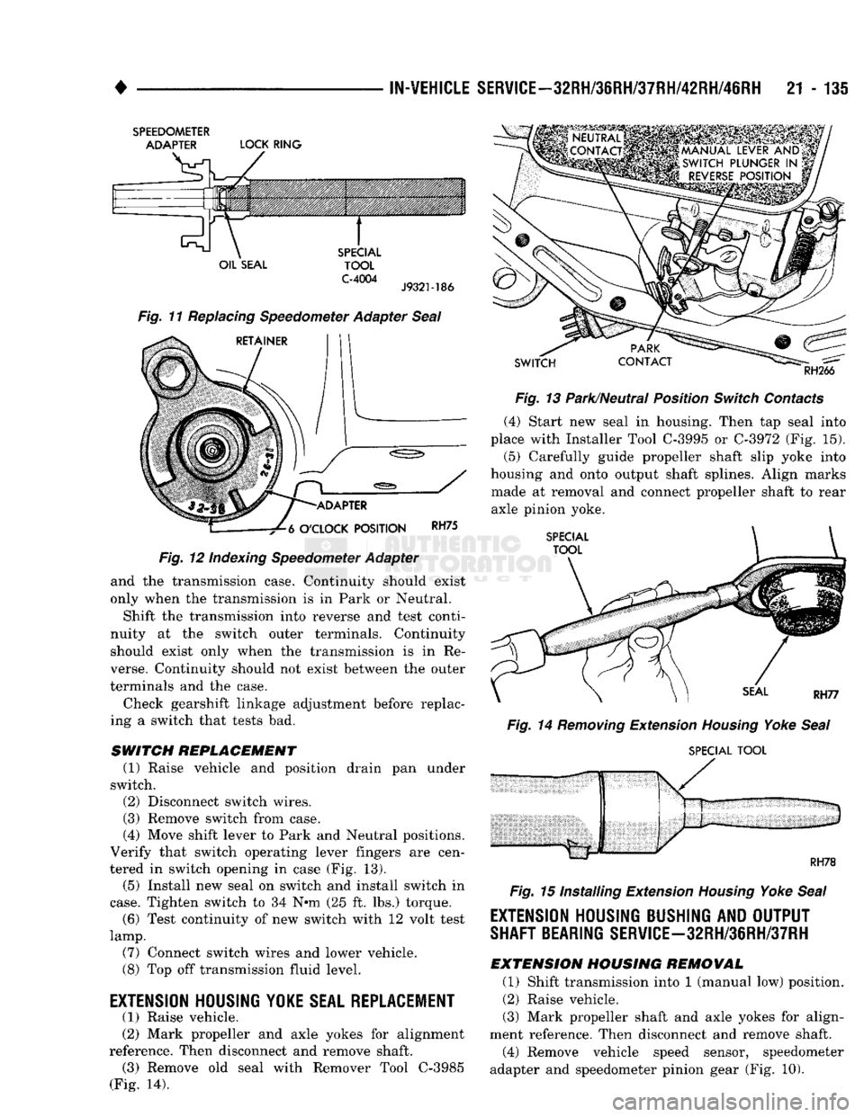
(4) Note range numbers on adapter face (Fig. 11).
These numbers correspond to number of teeth on pin ion.
(5) Install adapter in extension housing.
(6) Rotate adapter until required range numbers
are at six o-clock position (Fig. 12). Be sure adapter
range numbers correspond to number of teeth on pin ion.
(7) Seat adapter in housing.
(8) Install adapter clamp. Tighten clamp bolt to 11
N*m (100 in. lbs.) torque.
(9) Install vehicle speed sensor. Tighten sensor
coupling nut to 17 N*m (150 in. lbs.) torque and in
stall sensor wires.
(10) Lower vehicle and top off transmission fluid
level.
PARK/NEUTRAL
POSITION SWJTCH
The center terminal of the park/neutral position
switch is the starter circuit terminal. It provides the
ground for the starter solenoid circuit through the se
lector lever in Park and Neutral positions only. The
outer terminals on the switch are for the backup
lamp circuit.
SWITCH TEST To test the switch, remove the wiring connector.
Then test continuity between the center terminal
Page 1136 of 1502
•
IN-VEHICLE
SERVICE-32RH/3eRH/37RH/42RH/46RH
21 - 135
SPEEDOMETER
ADAPTER
LOCK
RING
OIL
SEAL
SPECIAL
TOOL
C-4004
J9321-186
Fig. 11 Replacing Speedometer Adapter Seal
RETAINER
-ADAPTER
-7^6
O'CLOCK
POSITION
RH75
Fig.
12 Indexing Speedometer Adapter
and the transmission case. Continuity should exist
only when the transmission is in Park or Neutral.
Shift the transmission into reverse and test conti
nuity at the switch outer terminals. Continuity should exist only when the transmission is in Re
verse. Continuity should not exist between the outer
terminals and the case.
Check gearshift linkage adjustment before replac
ing a switch that tests bad.
SWITCH
REPLACEMENT
(1) Raise vehicle and position drain pan under
switch. (2) Disconnect switch wires.
(3) Remove switch from case.
(4) Move shift lever to Park and Neutral positions.
Verify that switch operating lever fingers are cen
tered in switch opening in case (Fig. 13).
(5) Install new seal on switch and install switch in
case.
Tighten switch to 34 Nnn (25 ft. lbs.) torque. (6) Test continuity of new switch with 12 volt test
lamp.
(7) Connect switch wires and lower vehicle.
(8) Top off transmission fluid level.
EXTENSION HOUSING
YOKE
SEAL REPLACEMENT (1) Raise vehicle.
(2) Mark propeller and axle yokes for alignment
reference. Then disconnect and remove shaft. (3) Remove old seal with Remover Tool C-3985
(Fig. 14).
SWITCH
RH266
Fig.
13 Park/Neutral Position
Switch
Contacts (4) Start new seal in housing. Then tap seal into
place with Installer Tool
C-3995
or
C-3972
(Fig. 15).
(5)
Carefully guide propeller shaft slip yoke into
housing and onto output shaft splines. Align marks made at removal and connect propeller shaft to rear
axle pinion yoke.
SPECIAL
TOOL
Fig.
14
Removing
Extension
Housing
Yoke
Seal
SPECIAL
TOOL
RH78
Fig.
15 Installing Extension
Housing
Yoke
Seal
EXTENSION HOUSING BUSHING AND OUTPUT
SHAFT BEARING
SERVlCE-32RH/3eRH/37RH
EXTENSION
HOUSING
REMOVAL
(1) Shift transmission into 1 (manual low) position.
(2) Raise vehicle.
(3) Mark propeller shaft and axle yokes for align
ment reference. Then disconnect and remove shaft. (4) Remove vehicle speed sensor, speedometer
adapter and speedometer pinion gear (Fig. 10).
Page 1140 of 1502
•
IN-VEHICLE
SERVICE-32RH/36RH/37RH/42RH/46RH
21 - 139 (7) Push solenoid connector out of case.
(8) Remove valve body attaching screws.
(9) Lower valve body enough to remove accumula
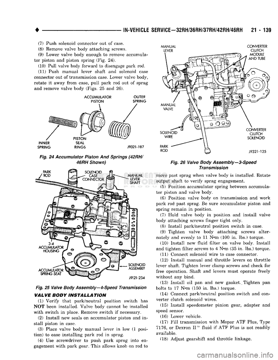
tor piston and piston spring (Fig. 24).
(10) Pull valve body forward to disengage park rod. (11) Push manual lever shaft and solenoid case
connector out of transmission case. Lower valve body,
rotate it away from case, pull park rod out of sprag and remove valve body (Figs. 25 and 26).
ACCUMULATOR
OUTER
PISTON
SPRING
INNER
SEAL
SPRING
RINGS
J932M87
Fig.
24
Accumulator
Piston
And
Springs
(42RH/
46RH
Shown)
Fig.
25
Valve
Body
Assembly—4-Speed
Transmission
VALVE
BODY
INSTALLATION
(1) Verify that park/neutral position switch has
NOT been installed. Valve body cannot be installed
with switch in place. Remove switch if necessary.
(2) Install new seals on accumulator piston and in
stall piston in case.
(3) Place valve body manual lever in low (1 posi
tion) to ease installing park rod in sprag.
(4) Use screwdriver to push park sprag into en
gagement with park gear. This allows knob on rod to
MANUAL
CONVERTER
LEVER
CLUTCH
- Fig. 26
Valve
Body
Assembly—3-Speed
Transmission
move past sprag when valve body is installed. Rotate
output shaft to verify sprag engagement. (5) Position accumulator spring between accumula
tor piston and valve body.
(6) Position valve body on transmission and work
park rod past sprag. Be sure accumulator piston and spring remain in position.
(7) Hold valve body in position and install valve
body attaching screws linger tight only.
(8) Install park/neutral position switch in case.
(9) Tighten valve body attaching screws alter
nately and evenly to 11 N#m (100 in. lbs.) torque.
(10) Install new fluid filter on valve body. Install
and tighten filter screws to 4 N-m (35 in. lbs.) torque. (11) Connect solenoid wire to case connector.
(12) Install manual and throttle levers on throttle
lever shaft. Tighten lever clamp screws and check for
free operation. Shaft and levers must operate freely
without any bind.
(13) Install oil pan and new gasket. (Tighten pan
bolts to 17 N»m (150 in. lbs.) torque. (14) Connect park/neutral position switch and con
verter clutch solenoid wires.
(15) Install speedometer pinion gear, adapter and
speed sensor.
(16) Lower vehicle.
(17) Fill transmission with Mopar ATF Plus, Type
7176,
or Dexron II™ fluid if ATF Plus is not readily
available. (18) Adjust gearshift and throttle linkage.
Page 1143 of 1502
!1
- 142
AUTOMATIC TRANSMISSION REMOVAL
AND
INSTALLATION
• AUTOMATIC TRANSMISSION REMOWAL AND INSTALLATION
INDEX
page
Dverdrlve
Unit
Installation
150
Overdrive
Unit
Removal-42RH/46RH
........ 149
Pump
Oil
Seal
146
Starter
Ring Gear Replacement
144
Torque Converter
and
Drive
Plate
Service
..... 144
Transmission
and
Torque Converter
Installation—
2-Wheel Drive
146
page
Transmission
and
Torque Converter
Installation—
4-Wheel Drive
. . .' 148
Transmission
and
Torque Converter Removal— 2-Wheel Drive
142
Transmission
and
Torque Converter Removal
—
4-Wheel Drive
143
TRANSMISSION
AND
TORQUE CONVERTER REMOVAL—2-WHEEL DRIVE The
transmission and torque converter should
be removed as an assembly to avoid component damage. The converter drive plate, pump bush
ing, or oil seal can be damaged if the converter
is left attached to the driveplate during removal. Be sure to remove the transmission and con
verter as an assembly.
(1) Raise vehicle.
(2) Disconnect or remove exhaust components as
needed for service access.
(3) Remove engine-to-transmission struts, if
equipped. (4) Disconnect fluid cooler lines at transmission.
(5) Remove starter motor and cooler line bracket.
(6) Remove torque converter bolt access cover.
(7) Remove transmission oil pan, drain fluid and
reinstall pan. (8) Remove transmission fill tube bracket bolts and
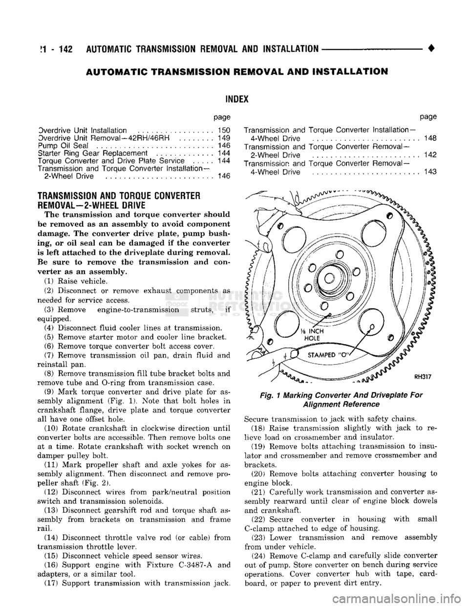
remove tube and O-ring from transmission case. (9) Mark torque converter and drive plate for as
sembly alignment (Fig. 1). Note that bolt holes in
crankshaft flange, drive plate and torque converter
all have one offset hole. (10) Rotate crankshaft in clockwise direction until
converter bolts are accessible. Then remove bolts one at a time. Rotate crankshaft with socket wrench on
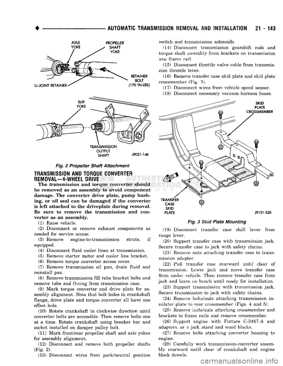
damper pulley bolt. (11) Mark propeller shaft and axle yokes for as
sembly alignment. Then disconnect and remove pro
peller shaft (Fig. 2). (12) Disconnect wires from park/neutral position
switch and transmission solenoids. (13) Disconnect gearshift rod and torque shaft as
sembly from brackets on transmission and frame
rail.
(14) Disconnect throttle valve rod (or cable) from
transmission throttle lever. (15) Disconnect vehicle speed sensor wires.
(16) Support engine with Fixture C-3487-A and
adapters, or a similar tool. (17) Support transmission with transmission jack.
Fig.
1 Marking Converter And
Driveplate
For
Alignment
Reference Secure transmission to jack with safety chains.
(18) Raise transmission slightly with jack to re
lieve load on crossmember and insulator. (19) Remove bolts attaching transmission to insu
lator and crossmember and remove crossmember and
brackets. (20) Remove bolts attaching converter housing to
engine block.
(21) Carefully work transmission and converter as
sembly rearward until clear of engine block dowels and crankshaft. (22) Secure converter in housing with small
C-clamp attached to edge of housing. (23) Lower transmission and remove assembly
from under vehicle.
(24) Remove C-clamp and carefully slide converter
out of pump. Store converter on bench during service
operations. Cover converter hub with tape, card
board, or paper to prevent dirt entry.
Page 1144 of 1502
•
AUTOMATIC TRANSMISSION REMOVAL
AND
INSTALLATION
21 - 143
AXLE
YOKE PROPELLER
SHAFT
YOKE
U-JOINT
RETAINER RETAINER
BOLT
(170
IN-LBS)
TRANSMISSION
OUTPUT
SHAFT
J9021-146
Fig.
2 Propeller Shaft Attachment
TRANSMISSION
AND TORQUE CONVERTER
REMOVAL—4-WHEEL
DRIVE
The transmission and torque converter should
be removed as an assembly to avoid component damage. The converter drive plate, pump bush
ing, or oil seal can be damaged if the converter
is left attached to the driveplate during removal.
Be sure to remove the transmission and con
verter as an assembly. (1) Raise vehicle.
(2) Disconnect or remove exhaust components as
needed for service access. (3) Remove engine-to-transmission struts, if
equipped. (4) Disconnect fluid cooler lines at transmission. (5) Remove starter motor and cooler line bracket.
(6) Remove torque converter access cover.
(7) Remove transmission oil pan, drain fluid and
reinstall pan. (8) Remove transmission fill tube bracket bolts and
remove tube and O-ring from transmission case. (9) Mark torque converter and drive plate for as
sembly alignment. Note that bolt holes in crankshaft
flange, drive plate and torque converter all have one
offset hole. (10) Rotate crankshaft in clockwise direction until
converter bolts are accessible. Then remove bolts one at a time. Rotate crankshaft using breaker bar and
socket installed on damper pulley bolt. (11) Mark front/rear propeller shaft and axle yokes
for assembly alignment. (12) Disconnect and remove both propeller shafts
(Fig. 2). (13) Disconnect wires from park/neutral position switch and transmission solenoids.
(14)
Disconnect transmission gearshift rods and
torque shaft assembly from brackets on transmission and frame rail.
(15) Disconnect throttle valve cable from transmis
sion throttle lever.
(16) Remove transfer case skid plate and skid plate
crossmember (Fig. 3). (17) Disconnect wires from vehicle speed sensor.
(18) Disconnect necessary vacuum harness hoses.
SKID
PLATE
CROSSMEMBER
TRANSFER
CASE
SKID
PLATE
J9121-525
Fig.
3
Skid
Plate
Mounting
(19) Disconnect transfer case shift lever from
range lever.
(20) Support transfer case with transmission jack.
Secure transfer case to jack with safety chains.
(21) Remove nuts attaching transfer case to trans
mission adapter.
(22) Pull transfer case rearward until clear of
transmission. Lower jack and move transfer case
from under vehicle. Then remove transfer case from
jack and leave on bench until ready for installation.
(23) Support transmission with transmission jack.
Secure transmission to jack with safety chains.
(24) Remove bolts/nuts attaching transmission in
sulator plate to rear crossmember (Figs. 4 and 5).
(25) Remove bolts/nuts attaching crossmember and
brackets to frame rails and remove crossmember.
(26) Support engine with Fixture C-3487-A and
adapters, or a jack stand and wood blocks.
(27) Remove bolts attaching converter housing to
engine. (28) Carefully work transmission-converter assem
bly rearward until clear of crankshaft and engine
block dowels.