1993 DODGE TRUCK sensor
[x] Cancel search: sensorPage 1357 of 1502
21 - 356 NP241
TRANSFER
CASE
•
TRANSFER
CASE
REMOVAL
(1) Raise vehicle.
(2) Position drain oil container under transfer case.
(3) Remove transfer case drain plug and drain lu
bricant into container. (4) Disconnect wires at vehicle speed sensor.
(5) Disconnect vacuum hoses at vacuum switch.
(6) Disconnect transfer case shift lever from range
lever. (7) Remove skid plate and skid plate crossmember.
(8) Support transmission with jack stand.
(9) Remove rear crossmember.
(10) Mark front and rear propeller shaft yokes for
assembly reference. (11) Remove front and rear propeller shafts.
(12) Support transfer case with suitable jack. Se
cure transfer case to jack with safety chains. (13) Remove nuts attaching transfer case to trans
mission. (14) Move transfer case assembly rearward until
free of transmission output shaft. (15) Lower jack and move transfer case from under
vehicle. (16) Remove all gasket material from rear of
transmission adapter housing.
TRANSFER CASE
INSTALLATION
(1) Apply Mopar Perfect Seal, silicone sealer, or
Permatex No. 2 to both sides of transfer case-to-
transmission gasket. Then position gasket on trans mission.
(2) Align and seat transfer case on transmission.
Be sure transfer case input gear splines are aligned
with transmission output shaft. Align splines by ro
tating transfer case rear output shaft yoke if neces sary. Do not install any transfer case attaching
nuts until the transfer case is completely seated against the transmission.
(3) Install and tighten transfer case attaching nuts
to 47 N*m (35 ft. lbs.). (4) Install rear crossmember.
(5) Remove jack stand from under transmission.
(6) Align and connect propeller shafts.
(7) Connect speed sensor wires and vacuum switch
hoses.
(8) Connect transfer case shift lever to range lever.
Tighten lever locknut to 10 N*m (90 in. lbs.). (9) Fill transfer case with recommended transmis
sion fluid. (10) Install transfer case fill plug.
(11) Install skid plate and skid plate crossmember.
(12) Lower vehicle.
TRANSFER CASE DISASSEMBLY
(2) Remove rear retainer (Figs. 2-3). Remove and
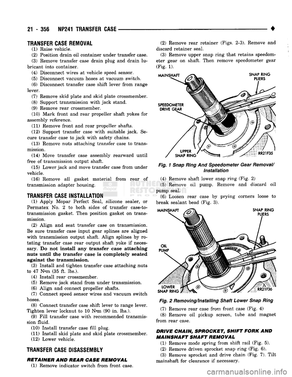
discard retainer seal. (3) Remove upper snap ring that retains speedom
eter gear on shaft. Then remove speedometer gear (Fig. 1).
Fig.
1
Snap Ring
And Speedometer Gear
Removal/
Installation
(4) Remove shaft lower snap ring (Fig. 2)
(5) Remove oil pump. Remove and discard oil
pump seal. (6) Loosen rear case by prying corners loose to
break sealant bead (Fig. 3).
Fig.
2 Removing/Installing Shaft
Lower
Snap Ring
(7) Remove rear case from front case (Fig. 4)
(8) Remove oil pickup screen, tube and magnet
from rear case.
DRIVE CHAIN, SPROCKET, SHIFT FORK
AND
MAINSHAFT SHAFT REMOVAL
(1) Remove mode spring from shift rail (Fig. 5).
(2) Remove driven sprocket snap ring (Fig. 6).
(3) Remove sprocket and drive chain (Fig. 7). Tilt
mainshaft for clearance if necessary.
RETAINER
AND
REAR CASE
REMOVAL
(1) Remove indicator switch from front case.
Page 1368 of 1502
•
TRANSMISSION/TRANSFER
CASE
SPECIFICATIONS
21 - 367
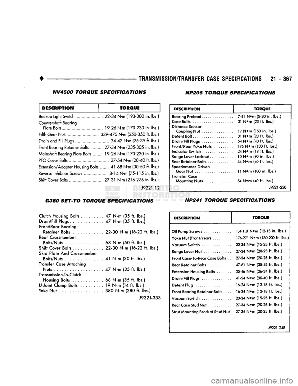
DESCRIPTION
TORQUE
Backup Light Switch 22-34 N-m (193-300 in.
lbs.)
Countershaft Bearing Plate Bolts 19-26 N-m (170-230 in.
lbs.)
Fifth Gear Nut 339-475 N-m (250-350
ft. lbs.)
Drain
and
Fill Plugs 34-47 N-m (25-35
ft. lbs.)
Front Bearing Retainer Bolts 27-34 N-m (235-305 in.
lbs.)
Mainshaft Bearing Plate Bolts 19-26 N-m (170-230 in.
lbs.)
PTO
Cover Bolts 27-54 N-rn (20-40
ft.
lbs.)
Extension/Adapter Housing Bolts 41-68 N-m (30-50
ft.
lbs.)
Reverse Inhibitor Screws
8-14
N-m (75-115 in.
lbs.)
Shift Cover Bolts 27-31 N-m (216-276 in.
lbs.)
J9221-12
DESCRIPTION
TORQUE
Bearing Preload
Case
Bolts
Distance
Sensor
Coupling
Nut
Detent
Bolt
Drain/Fill
Plugs
Front/Rear Yoke Nuts Indicator Switch
Range
Lever
Locknut..
Rear
Retainer
Bolts
...
Speedometer Driven Gear
Nut
Transfer
Case
Mounting
Nuts.
. . . . 7-41
N»m
(5-30
in.
lbs.)
31
mm (23 ft. lbs.)
17
N»m
(150
in.
lbs.)
31
N»m (23 ft. lbs.) 54
N«m
(40 ft. lbs.) 176
N®m
(130 ft. lbs.)
24
N«m
(18 ft. lbs.)
10 N*m (90 in. lbs.)
54
N«m
(40 ft. lbs.)
11
N»m (100
in.
lbs.)
54
N«m
(40 ft. lbs.) J9221-250
G360
SET-TO
TORQUE
SPECIFICATIONS
NP241
TORQUE SPECIFICATIONS
Clutch Housing Bolts
47 N-m (35 ft. lbs.)
Drain/Fill Plugs
47 Nm (35 ft. lbs.)
Front/Rear Bearing
Retainer Bolts
.
22-30
N-m
(16-22
ft. lbs.)
Rear Crossmember Bolts/Nuts
. 68 N-m (50 ft. lbs.)
Shift Cover Bolts 22-30
N-m
(16-22
ft. lbs.)
Skid Plate
And
Crossmember Bolts/Nuts
41 N-m (30 ft. lbs.)
Transfer Case Attaching Nuts
47 Nm (35 ft. lbs.)
Transmission-To-Clutch Housing Bolts
68 N-m (35 ft. lbs.)
U-Joint Clamp Bolts
19 Nm (14 ft. lbs.)
Yoke
Nut 380 N-m (280 ft. lbs.)
J9321-333
DESCRIPTION
TORQUE
Oil Pump
Screws
1.4-1.8
N«m (12-15 in. lbs.)
Yoke
Nut (front/rear) 176-271 N»m (130-200 ft. lbs.)
Vacuum Switch
20-34 N«m (15-25 ft. lbs.)
Range
Lever
Nut
27-34 N»m (20-25 ft. lbs.)
Front
Case-To-Rear
Case
Bolts
.. 27-34 N»m (20-25 ft. lbs.)
Rear
Retainer
Bolts
47-61 N»m (35-45 ft. lbs.)
Extension
Housing
Bolts
35-46 N»m (26-34 ft. lbs.)
Drain/Fill
Plugs
41-54 N*m (30-40 ft. lbs.)
Detent
Plug
16-24
N@m
(12-18 ft. lbs.)
Front
Bearing
Retainer
Bolts
16-24 N»m (12-18 ft. lbs.)
Vacuum Switch
20-34 N*m (15-25 ft. lbs.)
Rear
Case
Stud
Nut 27-34 N*m (20-25 ft. lbs.)
Strut
Mounting Bracket Stud
Nut 27-34 N»m (20-25 ft. lbs.)
J9221-248
NV4500
TORQUE
SPECIFICATIONS
NP205
TORQUE
SPECIFICATIONS
Page 1478 of 1502
•
EMISSION
CONTROL
SYSTEMS
25
- 1
CONTENTS
page page
AIR INJECTION
SYSTEM-o
9L
HDC-GAS EVAPORATIVE EMISSION CONTROLS
6
ENGINE
15
EXHAUST EMISSION CONTROLS
10
COMPONENT
REMOVAL/INSTALLATION
17
GENERAL INFORMATION
1
GENERAL
INFORMATION
Throughout this group, references are made
to
par
ticular vehicle models
by
alphabetical designation
or
by the particular vehicle nameplate.
A
chart showing a breakdown
of
alphabetical designations
is
included
in
the
Introduction section
at
the
beginning
of
this
manual.
The 5.9L (V-8) gas powered engine will
be
referred
to
in
this group
as
either the: LDC (Light Duty Cy cle)
or
HDC (Heavy Duty Cycle) engine.
The
HDC
engine can
be
easily identified
by
the
use
of
an en
gine mounted
air
injection pump. The 3.9L/5.2L/5.9L
LDC engine will not use
an
air
injection pump.
Maintenance requirements for LDC and HDC emis
sion systems differ because
of
different load
and
op
erating conditions. This section will cover emission control systems
for
the 3.9L (V-6), 5.2L (V-8), 5.9L LDC (V-8), 5.9L HDC (V-8) and 5.9L (in-line six cylinder) diesel engines.
SERVICE
REMINDER INDICATOR
(SRI)
LIGHT
The instrument panel mounted SRI light was for
merly referred
to as the
emission maintenance
re
minder (EMR) light.
It is
used with 5.9L HDC-gas
powered engines only.
It is
not
used with diesel
en
gines.
The SRI system
is
incorporated into the powertrain
control module (PCM)
(the
PCM
was
formerly
re
ferred
to as the
engine controller
or
SBEC).
The
PCM records
the
vehicles mileage and stores
it
into
memory every
8
miles. At that time, the PCM checks
for the 60,000 and 82,500 mileage trip points. When
the current mileage matches one
of
the above men
tioned trip points,
the
SRI light
is
activated.
The following parts are
to
be replaced
at
either the
indicated mileage
or
when the SRI light remains
on
when the key
is in
the ON position. After performing
the required maintenance,
the
SRI light must
be
re set
to
turn the light
off.
96,000
km
(60,000 miles):
• Replace EGR Valve
• Clean EGR passage • Replace PCV Valve
132,000
km
(82,500 miles):
• Replace Oxygen Sensor
Refer
to
Group
0,
Lubrication and Maintenance
for
all required maintenance schedules.
Failure
to
perform
the
required maintenance
and
only reset the SRI light may be
a
violation of federal
law. Only after performing
the
required mainte
nance, should the SRI light
be
reset.
RESETTING
SRI
LIGHT
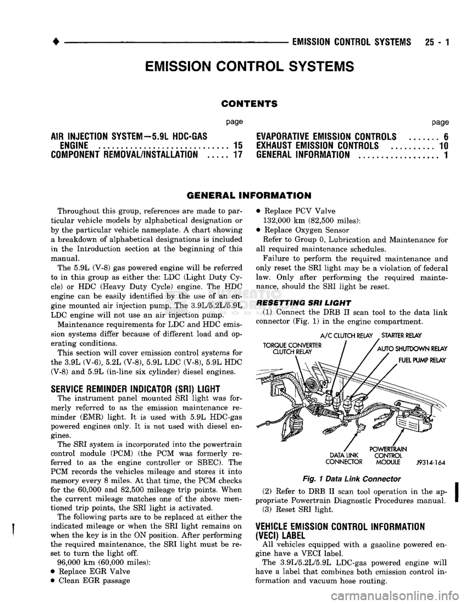
(1) Connect
the
DRB
II
scan tool
to
the
data link
connector (Fig.
1)
in
the engine compartment.
TORQUE CONVERTER
CLUTCH RELAY
A/C
CLUTCH RELAY
.
STARTER RELAY
AUTO
SHUTDOWN RELAY FUEL PUMP RELAY DATA LINK
CONNECTOR POWERTRAIN
CONTROL
MODULE
J9314-164
Fig.
1
Data
Link
Connector
(2) Refer
to
DRB
II
scan tool operation
in
the ap
propriate Powertrain Diagnostic Procedures manual. (3) Reset SRI light.
VEHICLE
EMISSION CONTROL INFORMATION
(VECI)
LABEL
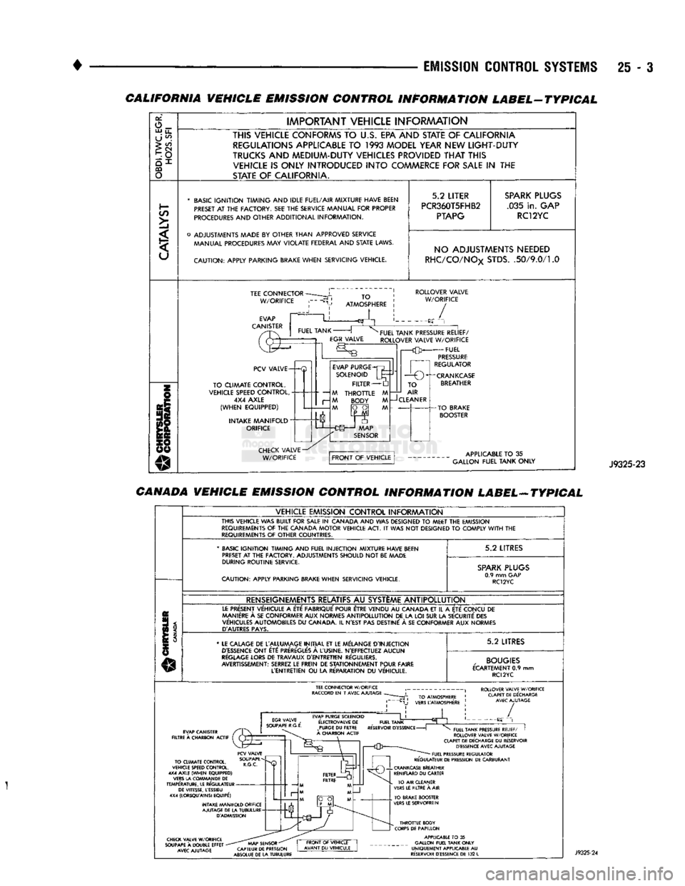
All vehicles equipped with
a
gasoline powered
en
gine have
a
VECI label. The 3.9L/5.2L/5.9L LDC-gas powered engine will
have
a
label that combines both emission control
in
formation and vacuum hose routing.
EMISSION CONTROL
SYSTEMS
Page 1480 of 1502
EMISSION
CONTROL SYSTEMS
25 - :
CALIFORNIA VEHICLE EMISSION CONTROL INFORMATION LABEL-TYPICAL
or,
o_ UJ
u_
U
^
>
CO
CQ
o
IMPORTANT
VEHICLE
INFORAAATION
THIS VEHICLE CONFORMS
TO
U.S.
EPA AND STATE
OF
CALIFORNIA REGULATIONS APPLICABLE
TO 1993
MODEL YEAR NEW
LIGHT-DUTY
TRUCKS
AND
MEDIUM-DUTY VEHICLES PROVIDED
THAT
THIS VEHICLE
IS
ONLY INTRODUCED
INTO
COMMERCE FOR
SALE
IN THE
STATE
OF
CALIFORNIA.
*
BASIC
IGNITION TIMING
AND
IDLE FUEL/AIR
MIXTURE HAVE BEEN
PRESET
AT THE
FACTORY.
SEE THE
SERVICE MANUAL
FOR
PROPER
PROCEDURES
AND
OTHER
ADDITIONAL
INFORMATION.
o
ADJUSTMENTS MADE
BY
OTHER
THAN
APPROVED
SERVICE MANUAL PROCEDURES
MAY
VIOLATE
FEDERAL
AND
STATE
LAWS.
CAUTION:
APPLY
PARKING BRAKE
WHEN
SERVICING
VEHICLE.
5.2
LITER
PCR360T5FHB2
PTAPG
SPARK
PLUGS
.035
in.
GAP RC12YC NO ADJUSTMENTS NEEDED
RHC/CO/NOx
STDS.
.50/9.0/1.0
TEE
CONNECTOR
W/ORIFICE
TO
ATMOSPHERE
ROLLOVER
VALVE
W/ORIFICE
/
PCV
VALVE-
TO
CLIMATE
CONTROL,
VEHICLE SPEED
CONTROL,
4X4
AXLE
(WHEN
EQUIPPED)
INTAKE
MANIFOLD"
ORIFICE
—
M
r-
M
EVAP
PURGE
SOLENOID
FILTER
THROTTLE
BODY
FUEL
TANK PRESSURE
RELIEF/
ROLLOVER
VALVE
W/ORIFICE
FUEL
PRESSURE
REGULATOR
1
r—O
O^-CRANKCASE
TO
AIR
CLEANER
APPLICABLE
TO
35
GALLON
FUEL
TANK
ONLY
J9325-23
CANADA VEHICLE EMISSION CONTROL INFORMATION LABEL-ATYPICAL
VEHICLE
EMISSION
CONTROL
INFORAAATION
THIS
VEHICLE
WAS
BUILT
FOR
SALE
IN
CANADA
AND WAS
DESIGNED
TO
MEET
THE
EMISSION
REQUIREMENTS
OF THE
CANADA
MOTOR
VEHICLE
ACT.
IT
WAS NOT
DESIGNED
TO
COMPLY
WITH
THE
REQUIREMENTS
OF
OTHER
COUNTRIES.
'
BASIC
IGNITION TIMING
AND
FUEL
INJECTION
MIXTURE HAVE BEEN
PRESET
AT
THE
FACTORY.
ADJUSTMENTS
SHOULD
NOT
BE
MADE
DURING
ROUTINE
SERVICE.
CAUTION:
APPLY
PARKING BRAKE
WHEN
SERVICING
VEHICLE.
5.2
LITRES
SPARK
PLUGS
0.9
mm GAP
RC12YC
RENSEIGNEMENTS RELATIFS
AU
SYSTEME
ANTIPOLLUTION
LE
PRESENT
VEHICULE
A
ETE
FABRIQUE'
POUR ETRE
VENDU
AU
CANADA
ET
IL
A
ETE
CONCU
DE
MANIERE
A
SE
CON
FORMER
AUX
NORMES
ANTIPOLLUTION
DE LA LOI SUR LA
SECURITE
DES
VEHICULES
AUTOMOBILES
DU
CANADA.
IL
N'EST
PAS
DESTINE'
A SE
CON
FORMER
AUX
NORMES
D'AUTRES
PAYS.
*
LE
CALAGE
DE
L'ALLUMAGE
INITIAL
ET LE
MELANGE
D'INJECTION
D'ESSENCE
ONT
ETC:
PREREGLE'S
A
L'USINE.
N'EFFECTUEZ
AUCUN
REGLAGE
LORS
DE
TRAVAUX
D'ENTRETIEN
REGULIERS.
AVERTISSEMENT:
SERREZ
LE
FREIN
DE
STATIONNEMENT
POUR
FAIRE
L'ENTRETIEN
OU
LA
RE'PARATION
DU
VEHICULE.
5.2
LITRES
,
BOUGIES
ECARTEMENT
0.9 mm
RC12YC
ROLLOVER VALVE W/ORIFICE CLAPET DE DECHARGE AVEC AJUTAGE EVAP PURGE SOLENOID
E'LECTROVALVE
DE
_
FUEL TANK PURGE
DU
FILTRE RESERVOIR
D'ESSENCE
-
A CHARBON ACTIF /
TO CLIMATE CONTROL,
VEHICLE SPEED CONTROL.
4X4 AXLE (WHEN EQUIPPED)
VERS LA COWMAN DE
DE
TEMPERATURE. LE REGULATEUR DE VITESSE, LESSIEU
4X4 (LORSQU'AINSI EQUIPE')
INTAKE MANIFOLD ORIFICE AJUTAGE DE LA TUBULURE D'ADMISSION FUEL TANK PRESSURE RELIEF/
I
ROLLOVER VALVE W/ORIFICE
CLAPET DE DECHARGE
DU
RESERVOIR D'ESSENCE AVEC AJUTAGE FUEL PRESSURE REGULATOR
REGULATEUR DE PRESSION DE CARBURANT CHECK VALVE W/ORIFICE
SOUPAPE
A
DOUBLE EFFET
-
AVEC AJUTAGE AAAP SENSOR
"
CAPTEUR DE PRESSION
ABSOLUE DE LA TUBULURE THROTTLE BODY
CORPS DE PAPILLON APPLICABLE
TO
35
GALLON FUEL TANK ONLY
UNIQUEMENT APPLICABLE
AU
RESERVOIR D'ESSENCE DE
132
L
Page 1481 of 1502
2i
- 4
EMISSION
CONTROL
SYSTEMS
•
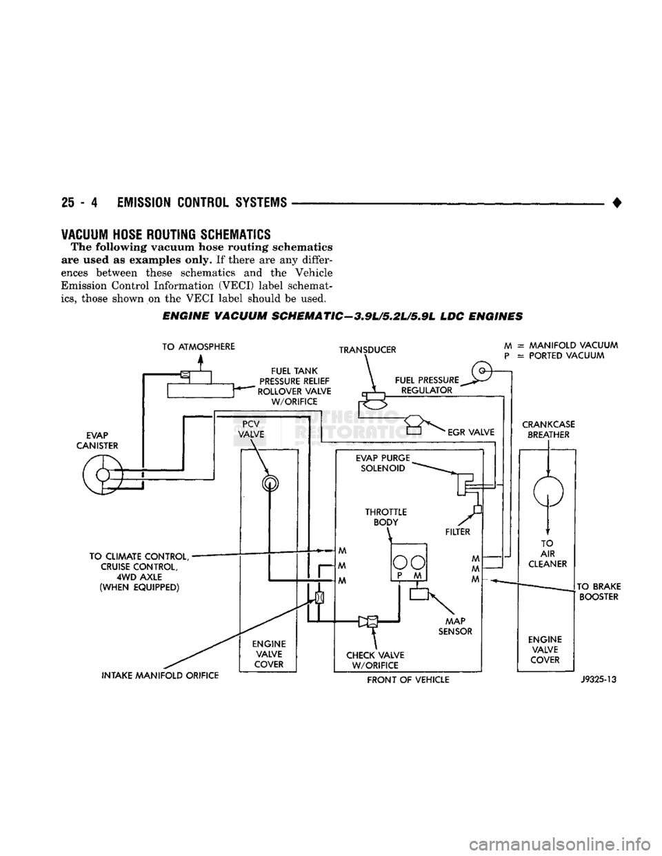
VACUUM
HOSE
ROUTING
SCHEMATICS
The following vacuum hose routing schematics
are used
as
examples only.
If
there
are any
differ
ences between these schematics
and the
Vehicle
Emission Control Information (VECI) label schemat
ics,
those shown
on the
VECI label should
be
used.
ENGINE
VACUUM
SCHEMATIC-3.9U5.2L/5.9L
LDC
ENGINES
TO ATMOSPHERE
i
TRANSDUCER
FUEL
TANK
PRESSURE
RELIEF
ROLLOVER VALVE
W/ORIFICE
EVAP
CANISTER
TO CLIMATE CONTROL,
CRUISE
CONTROL,
4WD
AXLE
(WHEN
EQUIPPED) INTAKE
MANIFOLD
ORIFICE ENGINE
VALVE
COVER FUEL PRESSURE
REGULATOR
M
P
= MANIFOLD VACUUM
= PORTED VACUUM
"8^
EGR
VALVE
EVAP PURGE SOLENOID MAP
SENSOR
CHECK VALVE W/ORIFICE
CRANKCASE
BREATHER
TO
AIR
CLEANER
ENGINE VALVE
COVER TO BRAKE
BOOSTER FRONT
OF
VEHICLE
J9325-13
Page 1487 of 1502
25-10
EMISSION
CONTROL
SYSTEMS
EXHAUST
EMISSION
CONTROLS
INDEX
page
Air Inlet—5.9L Diesel
Engine
13
Exhaust
Gas Recirculation (EGR)
Systems
10
HEATED
INLET
AIR
SYSTEM
The air filter housing mounted-heated inlet air sys
tem is no longer used on any Dodge Truck gas pow ered engine.
EXHAUST
GAS
RECIRCULATION
(EGR)
SYSTEMS
GENERAL INFORMATION The EGR system reduces oxides of nitrogen (NOx)
in the engine exhaust and helps prevent spark
knock. This is accomplished by allowing a predeter
mined amount of hot exhaust gas to recirculate and
dilute the incoming fuel/air mixture. This dilution
reduces peak flame temperature during combustion.
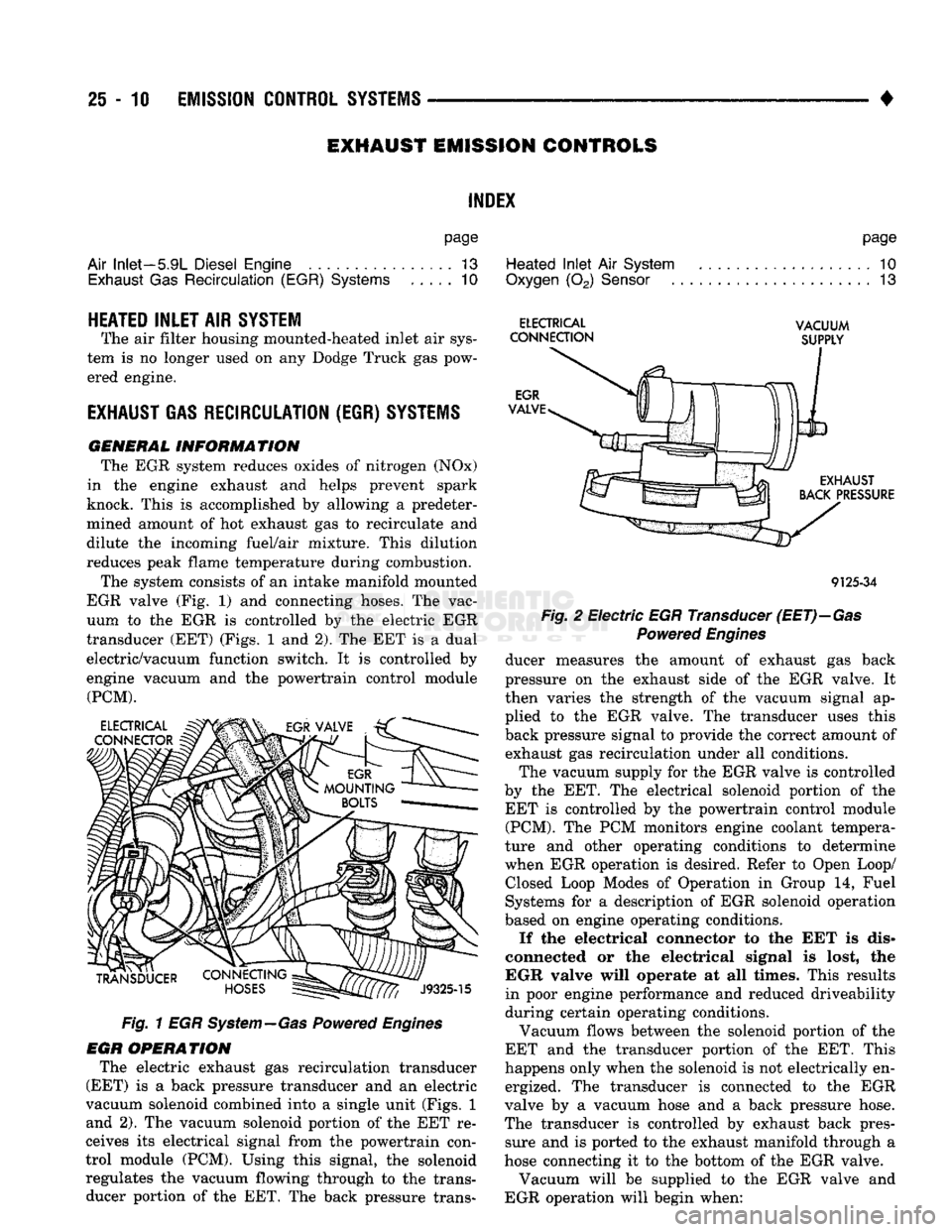
The system consists of an intake manifold mounted
EGR valve (Fig. 1) and connecting hoses. The vac
uum to the EGR is controlled by the electric EGR
transducer (EET) (Figs. 1 and 2). The EET is a dual
electric/vacuum function switch. It is controlled by
engine vacuum and the powertrain control module (PCM).
Fig. 1 EGR System—Gas Powered Engines
EGR OPERATION The electric exhaust gas recirculation transducer
(EET) is a back pressure transducer and an electric
vacuum solenoid combined into a single unit (Figs. 1 and 2). The vacuum solenoid portion of the EET re
ceives its electrical signal from the powertrain con
trol module (PCM). Using this signal, the solenoid regulates the vacuum flowing through to the trans ducer portion of the EET. The back pressure trans-
page
Heated
Inlet
Air
System
. 10
Oxygen
(02)
Sensor
13
ELECTRICAL
VACUUM
CONNECTION
SUPPLY
9125-34
Fig.
2 Electric EGR Transducer
(EET)—Gas
Powered
Engines
ducer measures the amount of exhaust gas back
pressure on the exhaust side of the EGR valve. It
then varies the strength of the vacuum signal ap
plied to the EGR valve. The transducer uses this
back pressure signal to provide the correct amount of exhaust gas recirculation under all conditions.
The vacuum supply for the EGR valve is controlled
by the EET. The electrical solenoid portion of the EET is controlled by the powertrain control module (PCM). The PCM monitors engine coolant tempera
ture and other operating conditions to determine
when EGR operation is desired. Refer to Open Loop/ Closed Loop Modes of Operation in Group 14, Fuel
Systems for a description of EGR solenoid operation
based on engine operating conditions.
If the electrical connector to the EET is dis
connected or the electrical signal is lost, the
EGR valve will operate at all times. This results
in poor engine performance and reduced driveability
during certain operating conditions.
Vacuum flows between the solenoid portion of the
EET and the transducer portion of the EET. This
happens only when the solenoid is not electrically en ergized. The transducer is connected to the EGR
valve by a vacuum hose and a back pressure hose.
The transducer is controlled by exhaust back pres sure and is ported to the exhaust manifold through a
hose connecting it to the bottom of the EGR valve.
Vacuum will be supplied to the EGR valve and
EGR operation will begin when:
Page 1488 of 1502
•
EMISSION
CONTROL
SYSTEMS
25 - 11 • The electrical solenoid portion of the EET is not
energized.
• The engine back pressure entering the EGR valve
inlet is strong enough to close the transducer bleed
valve.
If back pressure is not strong enough to close the
transducer bleed valve, the transducer will bleed off the vacuum preventing EGR operation.
When the electrical solenoid portion of the EET is
de-energized by the powertrain control module (PCM), vacuum flows to the transducer. The trans
ducer is connected to the engine exhaust system by a small hose that connects to the base of the EGR
valve.
The vacuum section of the transducer is controlled
by exhaust system back pressure. When back pres sure is high enough it will close a bleed valve in the
transducer allowing vacuum to actuate the EGR
valve. If back pressure does not close the bleed valve,
vacuum will be bled off.
For more information, refer to Group 14, Fuel Sys
tems.
Refer to the Component Removal/Installation sec
tion of this group for EGR valve replacement proce
dures.
EGR SYSTEM ON-BOARD DIAGNOSTICS
(CALIFORNIA VEHICLES
ONLY)
The powertrain control module (PCM) performs an
On-Board Diagnostic (OBD) check of the EGR system
on all California vehicles. The diagnostic system uses
the electric EGR transducer (EET) for the system
tests.
The OBD check activates only during selected en
gine/driving conditions. When the conditions are met,
the PCM energizes the EET solenoid to disable the EGR. The PCM checks for a change in the oxygen sensor signal. If the air-fuel mixture goes lean, the
PCM will attempt to enrichen the mixture. The PCM
registers a diagnostic trouble code (DTC) if the EGR system has failed or degraded. After registering a
DTC,
the PCM turns the malfunction indicator
lamp (MIL) on. (The malfunction indicator lamp was formerly referred to as the check engine lamp). The
malfunction indicator lamp indicates the need for im
mediate service.
If a malfunction is indicated by the malfunction in
dicator lamp and a DTC for the EGR system was set,
check for proper operation of EGR system. Use the
following: System Test, EGR Gas Flow Test and EGR
Diagnosis Chart.
If the EGR system tests properly, check the system
using the DRB II scan tool. For use of the DRB II,
refer to the appropriate Powertrain Diagnostics Pro cedure service manual. EGR SYSTEM SERVICE
A malfunctioning EGR system can cause engine
spark knock, sags or hesitation, rough idle, engine
stalling and poor driveability. To be sure of proper
operation of the EGR system, inspect all passages for
blockage. Check moving parts for binding. Inspect
the complete system for leaks. Replace system com ponents or hoses that are leaking.
Inspect all hose connections between throttle body,
intake manifold, EGR valve and EGR purge solenoid.
Replace any vacuum harness components that are
leaking or damaged. Refer to EGR Control System Test and EGR Gas
Flow Test to check EGR System operation.
EGR GAS FLOW TEST (1) Disconnect hose from EGR valve and connect a
hand vacuum pump to EGR valve nipple. Apply a
minimum of 12 inches vacuum the valve.
(2) The engine should now idle roughly or stall. If
this occurs, the valve is performing correctly. Proceed
to Electric EGR Transducer Test.
(3) If the engine idle speed did not change, remove
the EGR valve and inspect the valve and the exhaust passage in the manifold for blockage. Repair as nec
essary. If blockage is not present, replace the EGR
valve.
ELECTRIC EGR TRANSDUCER (EET)
TESTING ELECTRIC SOLENOID PORTION OF TRANSDUCER
(1) Bring the engine to normal operating tempera
ture.
Operate at idle speed. Test the EET as follows: (2) Check vacuum at EET vacuum source. Discon
nect the hose and attach a vacuum gauge to it.
(3) Vacuum should be a minimum of 15 inches:
• If vacuum is low, check the line for kinks, twists
or a loose connection at vacuum connector or intake
manifold.
• If vacuum is correct, remove gauge. Connect the
vacuum line and proceed to next step. (4) Check EET operation using the appropriate
Powertrain Diagnostic Procedures service manual.
Refer to this manual for use of the DRB II scan tool and repair EET as necessary.
TESTING VACUUM PORTION
OF
TRANSDUCER
(1) Disconnect the EET vacuum lines, back pres
sure line and electrical connector. Remove trans
ducer.
(2) Plug the EET EGR valve port.
(3) Apply 1-2 pounds air pressure to exhaust back
pressure port. Air pressure can be supplied with a
hand operated air pump or compressed air (regulated
to correct psi).
(4) Apply a minimum of 12 inches of vacuum to
vacuum supply port.
Replace the EET if it will not hold vacuum.
Page 1490 of 1502
EMISSION
CONTROL
SYSTEMS
25 - 13
For electrical tests
of the EET and its
circuitry,
re
fer
to the
appropriate Powertrain Diagnostic Proce dures service manual
for use of the DRB II
scan tool.
Refer
to the
Component Removal/Installation sec
tion
of
this group
for EET
replacement procedures.
OXYGEN
(02)
SENSOR
For description, operation, diagnosis
and
removal/
installation procedures
of the 02
sensor, refer
to
Group
14,
Fuel Systems.
AIR
INLET—5.9L
DIESEL
ENGINE
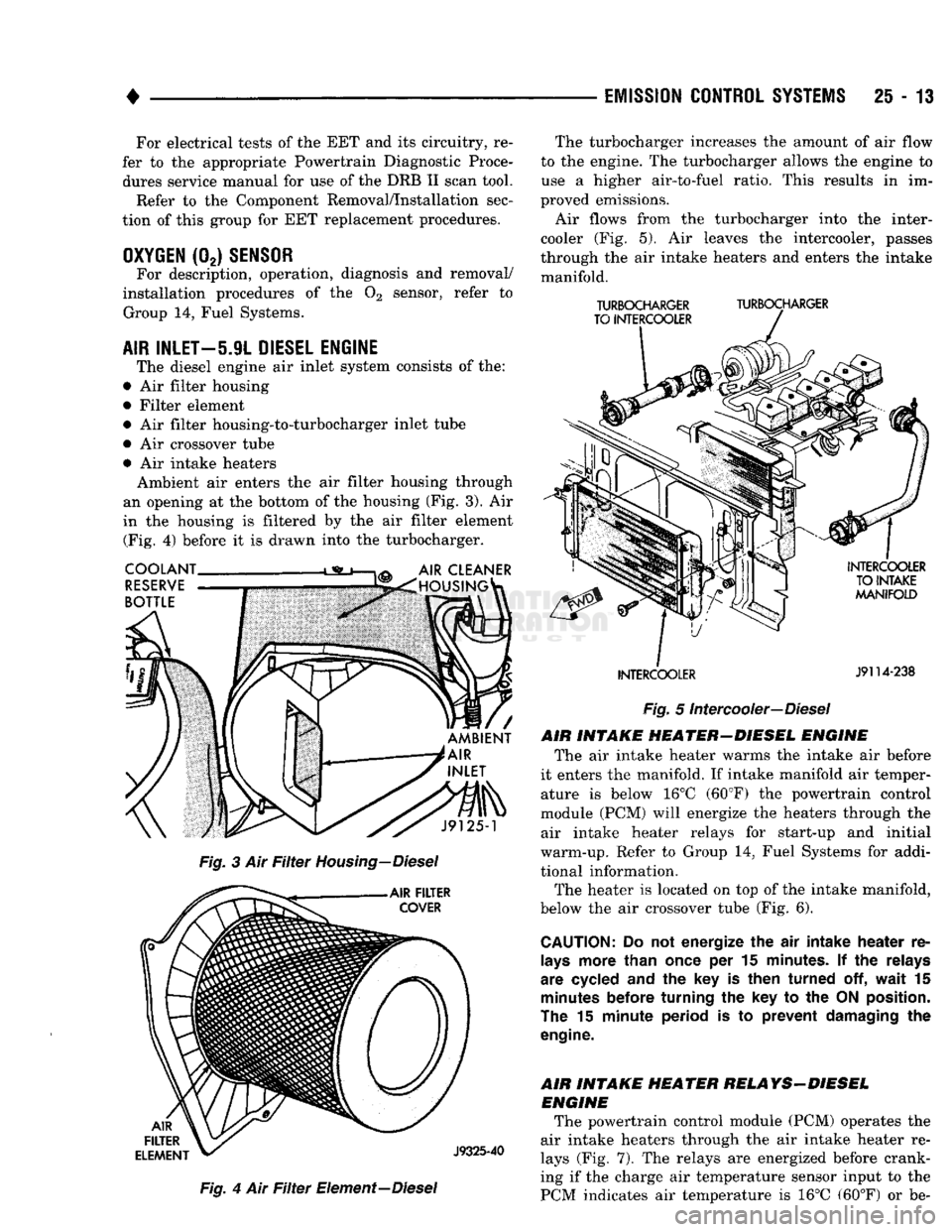
The diesel engine
air
inlet system consists
of the:
•
Air
filter housing
• Filter element •
Air
filter housing-to-turbocharger inlet tube
•
Air
crossover tube •
Air
intake heaters Ambient
air
enters
the air
filter housing through
an opening
at the
bottom
of the
housing
(Fig. 3). Air
in
the
housing
is
filtered
by the air
filter element (Fig.
4)
before
it is
drawn into
the
turbocharger.
Fig.
4 Air Filter
Element—Diesel The turbocharger increases
the
amount
of air
flow
to
the
engine.
The
turbocharger allows
the
engine
to
use
a
higher air-to-fuel ratio. This results
in im
proved emissions.
Air flows from
the
turbocharger into
the
inter-
cooler
(Fig. 5). Air
leaves
the
intercooler, passes
through
the air
intake heaters
and
enters
the
intake manifold.
TURBOCHARGER
TURBOCHARGER
TO INTERCOOLER
INTERCOOLER
J9114-238
Fig.
5
Intercooler—Diesel
AIR INTAKE HEATER-DIESEL ENGINE The
air
intake heater warms
the
intake
air
before
it enters
the
manifold.
If
intake manifold
air
temper ature
is
below
16°C
(60°F)
the
powertrain control
module
(PCM)
will energize
the
heaters through
the
air intake heater relays
for
start-up
and
initial
warm-up. Refer
to
Group
14,
Fuel Systems
for
addi
tional information. The heater
is
located
on top of the
intake manifold,
below
the air
crossover tube
(Fig. 6).
CAUTION:
Do not
energize
the air
intake heater
re
lays
more than once
per 15
minutes.
If the
relays
are cycled
and the key is
then turned
off,
wait
15
minutes
before turning
the key to the
ON
position.
The
15
minute period
is to
prevent damaging
the
engine.
AIR INTAKE HEATER RELAYS-DIESEL ENGINE The powertrain control module
(PCM)
operates
the
air intake heaters through
the air
intake heater
re
lays
(Fig. 7). The
relays
are
energized before crank
ing
if the
charge
air
temperature sensor input
to the
PCM indicates
air
temperature
is 16°C
(60°F)
or be-