1993 DODGE TRUCK clutch
[x] Cancel search: clutchPage 155 of 1502
3
- 28
REAR
SUSPENSION
AND
AXLE
•
SURE-GRIP
DIFFERENTIAL
SERVICE
GENERAL
INFORMATION
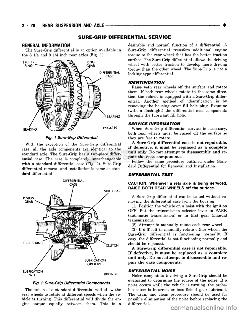
The Sure-Grip differential
is an
option available
in
the
8 1/4 and 9 1/4
inch rear axles
(Fig. 1).
EXCITER
RING RING
GEAR
DIFFERENTIAL
CASE
BEARING BEARING
J9003-119
Fig.
1
Sure-Grip
Differential
With
the
exception
of the
Sure-Grip differential
case,
all the
axle components
are
identical
to the
standard axle.
The
Sure-Grip
has a
two-piece differ
ential case.
The
case
is
completely interchangeable
with
a
standard differential case
(Fig. 2).
Sure-Grip differential removal
and
installation
is
same
as
stan
dard differential.
DIFFERENTIAL
CASE
PINION
GEAR
COIL SPRING LUBRICATION
WELL
SIDE
GEAR
CLUTCH
LUBRICATION
GROOVES
J9003-120
Fig.
2
Sure-Grip
Differential
Components
The action
of a
standard differential will allow
the
rear wheels
to
rotate
at
different speeds when
the ve
hicle
is
turning. This differential will divide
the en
gine torque equally between them. This
is a
desirable
and
normal function
of a
differential.
A
Sure-Grip differential transfers additional engine
torque
to the
rear wheel that
has the
better traction surface.
The
Sure-Grip differential allows
the
driving
wheel with better traction
to
develop more driving
torque than
the
other wheel.
The
Sure-Grip
is not a
locking type differential.
IDENTIFICATION Raise both rear wheels
off the
surface
and
rotate
them.
If
both rear wheels rotate
in the
same direc
tion,
the
vehicle
is
equipped with
a
Sure-Grip differ ential. Another method
of
identification
is by
removing
the
housing cover fill hole plug. Examine (with
a
flashlight)
the
differential case components
through
the
lubricant fill hole.
SERVICE INFORMATION When Sure-Grip differential service
is
necessary,
both rear wheels must
be
raised
off the
surface
so
they
are
free
to
rotate.
A Sure-Grip differential case
is not
repairable.
If defective,
it
must
be
replaced
as a
complete
unit only.
Do not
attempt
to
disassemble
and re
pair
the
case components.
Follow
the
same procedure outlined under Stan
dard Differential
for
Removal
and
Installation.
DIFFERENTIAL TEST
CAUTION:
Whenever
a
rear axle
is
being
serviced,
RAISE
BOTH
REAR
WHEELS
off the
surface.
A Sure-Grip differential
can be
tested without
re
moving
the
differential case from
the
housing.
(1) Position
the
vehicle
on a
hoist with
the
ignition
OFF.
Put the
transmission selector lever
in
PARK
(automatic transmission)
or in
first gear (manual
transmission).
(2) Attempt
to
manually rotate each rear wheel.
(3)
If
difficult
to
manually rotate either wheel,
the
Sure-Grip differential
is
functioning normally.
If
easy,
the
differential
is not
functioning normally
and
should
be
replaced.
A Sure-Grip differential case
is not
repairable.
If defective,
it
must
be
replaced
as a
complete
unit only.
Do not
attempt
to
disassemble
and re
pair
the
case components.
DIFFERENTIAL NOISE Noise complaints involving
a
Sure-Grip should
be
evaluated
to
determine
the
source
of the
noise.
If a
noise occurs while
the
vehicle
is
turning,
the
proba
ble cause
is
incorrect
or
insufficient gear lubricant. The drain
and
clean procedure should
be
used
for
possible elimination
of the
noise before replacing
the
differential.
Page 156 of 1502
•
REAR
SUSPENSION
AND
AXLE
3-29
WARNING: WHEN SERVICING VEHICLES
WITH
SURE-GRIP,
DO NOT
USE THE ENGINE
TO
ROTATE
THE AXLE
AND
WHEELS. BOTH REAR WHEELS MUST BE RAISED AND
THE
VEHICLE SUPPORTED.
A
SURE-GRIP AXLE
CAN
EXERT ENOUGH FORCE
(IF ONE
WHEEL
IS IN
CONTACT
WITH
THE
SUR FACE)
TO
CAUSE
THE
VEHICLE
TO
MOVE.
LUBRICATION
Multi-Purpose Gear Lubricant, as defined by MIL-
L-2105-B (API GL-5) should be used in all axles.
MOPAR Hypoid Lubricant is recommended or equiv alent. In Sure-Grip differentials 4 ounces of MOPAR Hy
poid Gear Lubricant Additive must be added with each re-fill.
It is recommended the vehicle be driven through 10
to 12 slow, figure-eight turns. This ensures the lubri cant is thoroughly pumped through the Sure-Grip
differential clutches.
MODEL 60 and 70 AXLES
INDEX
page
Axle Shaft Removal/Installation
32
Complete Axle Removal/Installation
........... 33
Differential
Assembly
38
Differential
Disassembly
34
Drain
and Refill 31
General
Information
29
Lubricant
31
GENERAL
INFORMATION
The housing (Fig. 1) consists of an iron center cast
ing with axle shaft tubes extending from either side.
The tubes are pressed in to form a one-piece axle housing. The integral type housing, hypoid gear design has
the centerline of the pinion set below the centerline of the ring gear. The axles are equipped with full-floating axle
shafts,
meaning that loads are supported by the axle
housing tubes. The full-float axle shafts are retained
by bolts attached to the hub. The hub rides on two
bearings at the outboard end of the axle tube. The axle shafts can be removed without disturbing or re
moving the wheel bearings. The wheel bearings are
opposed tapered roller bearings that are part of the
hub/drum assembly.
page
Pinion Gear Depth Measurement
and
Adjustment
with Tool Set C-758-D6 43
Pinion Gear Depth Measurement
and
Adjustment
with
Tool
Set
D-116
. 40
Pinion Shaft Seal
31
Specifications
50
Wheel Bearing Service
33
The removable, stamped steel cover provides a
means for inspection and service without removing
the complete axle from the vehicle.
A small, stamped metal axle gear ratio identifica
tion tag is attached to the housing cover via one of
the cover bolts. This tag also identifies the number of
ring and pinion teeth.
The differential case is a one-piece design. The
dif
ferential pinion mate shaft is retained with a roll
pin. Model 70 axles with the optional Powr-Lok use a
two piece differential case. Differential bearing pre load and ring gear backlash are adjusted by the use
of shims located between the differential bearing
cones and case.
Page 158 of 1502
•
REAR
SUSPENSION
AND
AXLE
3 - 31
LUBRICANT
Hypoid gear lubricant, as defined by MIL-L-2105-B
and API GL 5 is the specified lube. MOPAR Hypoid
Gear Lubricant conforms with both of these specifica
tions and is highly recommended.
CAUTION:
If a
rear
axle
is
submerged
in
water,
the
axle
lubricant
must
be
replaced
immediately,
DRAIN
AND
REFILL
(1) Drive the vehicle until the gear lubricant
reaches normal operating temperature. (2) Raise and support the vehicle. (3) Remove the lubricant fill hole plug from the
differential housing cover. (4) Remove the differential housing cover. Allow
the lubricant to completely drain from the housing and axle shaft tubes. (5) Flush the differential and the housing cavity
with a flushing oil to remove residual lubricant and
foreign matter. Do not use water,
steam,
kerosene
or
gasoline for
flushing,
(6) Scrape the residual gasket from the housing
and cover mating surfaces. Clean the mating sur
faces with mineral spirits. Install a new cover gas
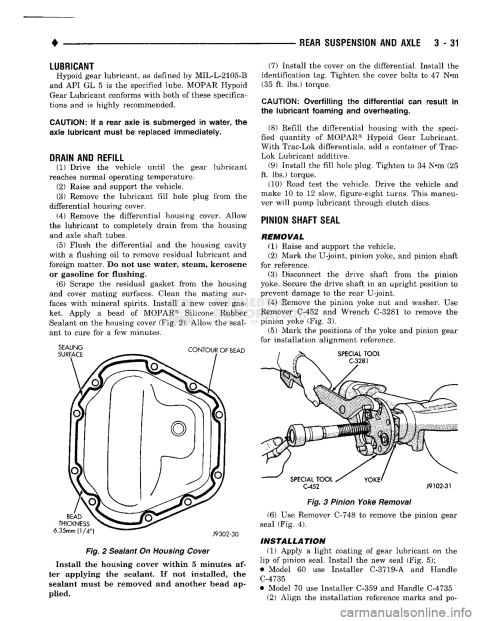
ket. Apply a bead of MOPAR® Silicone Rubber Sealant on the housing cover (Fig. 2). Allow the seal
ant to cure for a few minutes.
SEALING
SURFACE
CONTOUR
OF
BEAD
BEAD
THICKNESS
6.35mm
(1/4")
J9302-30
Fig.
2 Sealant On Housing Cower
Install
the
housing
cover
within 5
minutes
af
ter
applying
the
sealant.
If not
installed,
the
sealant
must be
removed
and another
bead
ap
plied.
(7) Install the cover on the differential. Install the
identification tag. Tighten the cover bolts to 47 Nem (35 ft. lbs.) torque.
CAUTION:
Overfilling
the differential" can
result
in
the
lubricant
foaming
and
overheating.
(8) Refill the differential housing with the speci
fied quantity of MOPAR® Hypoid Gear Lubricant.
With Trac-Lok differentials, add a container of Trac-
Lok Lubricant additive.
(9) Install the fill hole plug. Tighten to 34 N-m (25
ft. lbs.) torque.
(10) Road test the vehicle. Drive the vehicle and
make 10 to 12 slow, figure-eight turns. This maneu
ver will pump lubricant through clutch discs.
PINION
SHAFT
SEAL
REMOVAL
(1) Raise and support the vehicle.
(2) Mark the U-joint, pinion yoke, and pinion shaft
for reference.
(3) Disconnect the drive shaft from the pinion
yoke. Secure the drive shaft in an upright position to
prevent damage to the rear U-joint.
(4) Remove the pinion yoke nut and washer. Use
Remover C-452 and Wrench C-3281 to remove the
pinion yoke (Fig. 3).
(5) Mark the positions of the yoke and pinion gear
for installation alignment reference.
SPECIAL
TOOL
C-3281
SPECIAL
TOOL
C-452
J9102-31
Fig.
3 Pinion Yoke
Removal
(6) Use Remover C-748 to remove the pinion gear
seal (Fig. 4).
INSTALLATION
(1) Apply a light coating of gear lubricant on the
lip of pinion seal. Install the new seal (Fig. 5);
• Model 60 use Installer C-3719-A and Handle C-4735
• Model 70 use Installer C-359 and Handle C-4735 (2) Align the installation reference marks and po-
Page 178 of 1502
REAR
SUSPENSION
AND
AXLE
3 - 51
TRAC-LOK
DIFFERENTIAL
SERVICE
INFORMATION
Model
60 rear
axles equipped
with
Trac-Lok
differ
ential are optionally available for Ram Truck vehi
cles.
DIFFERENTIAL
NOISE
Noise complaints involving Trac-Lok should be
evaluated to determine the source of the noise. If a noise occurs while the vehicle is turning, the proba
ble cause is incorrect or insufficient gear lubricant. Replace the axle gear lubricant and add MOPAR Hy
poid Gear Lubricant Additive. If the chatter persists, clutch disc damage could have occurred.
WARNING: WHEN SERVICING VEHICLES
WITH
A
TRAC-LOK DIFFERENTIAL,
DO NOT
USE
THE EN
GINE
TO
ROTATE
THE
AXLE
AND
WHEELS.
BOTH
REAR
WHEELS MUST
BE
RAISED, FROM
THE
SUR
FACE
AND THE
VEHICLE SUPPORTED. TRAC-LOK
CAN EXERT ENOUGH DRIVING FORCE
TO
CAUSE
THE VEHICLE
TO
MOVE.
(4) Place a block of wood that is 2 inches high and
a minimum of 3 inches wide in front of one of the
front tires.
(5) With a gradual throttle opening, attempt to
slowly drive the vehicle over the block of wood.
(6) If the Kraft paper slips out before the front
wheel moves over the block of wood; reposition the vehicle so paper and board are under the opposite
rear wheel. Attempt to drive over the block of wood
the second time.
(7) If the front wheel moves over the block of wood,
the axle can be considered to be functioning nor mally.
LUBRICANTS
The lubricant recommended for Trac-Lok differen
tial is API grade GL 5. A container of Trac-Lok Lu
bricant (friction modifier) should be added after service. Refer to Group 0, Lubrication and Maintenance for
additional information.
DIFFERENTIAL
TEST
(1) Drive the vehicle to thoroughly warm up the
lubricant in the rear axle. (2) Place a large piece of Kraft paper over a
smooth Formica board.
(3) Drive the vehicle over the Formica board until
one rear wheel/tire is in the center of the board and
paper.
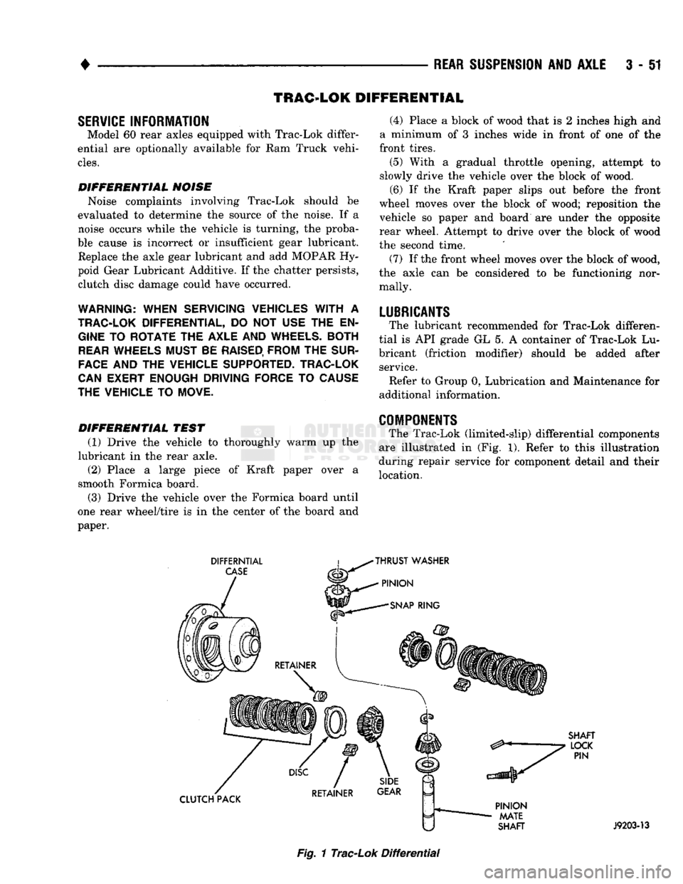
COMPONENTS
The Trac-Lok (limited-slip) differential components
are illustrated in (Fig. 1). Refer to this illustration
during repair service for component detail and their
location.
DIFFERNTIAL
CASE
THRUST
WASHER
PINION
SNAP
RING
SHAFT
LOCK
PIN
CLUTCH PACK
PINION
MATE
SHAFT
J9203-13
Fig.
1
Trac-Lok
Differential
Page 180 of 1502
•
REAR SUSPENSION
AND
AXLE
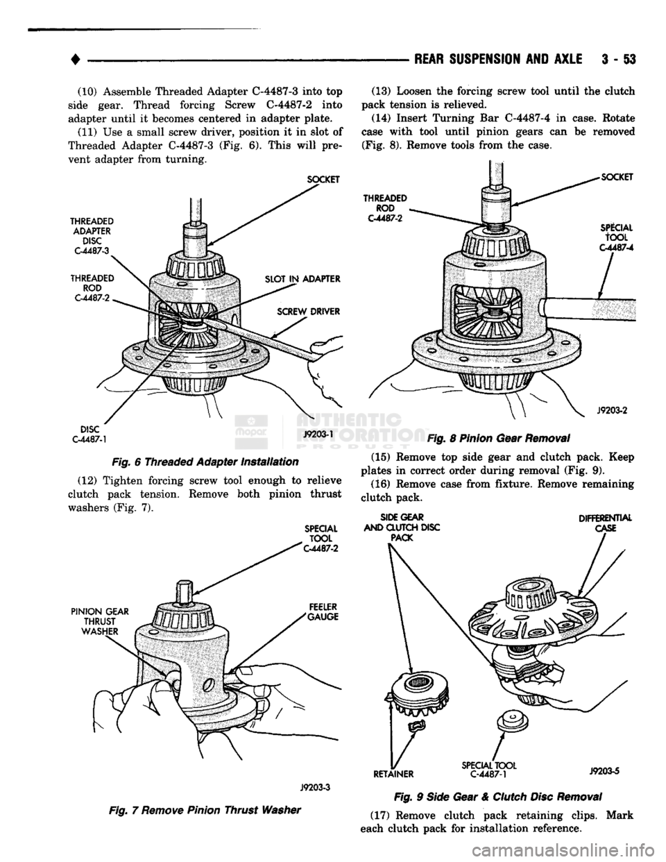
3 - §3 (10) Assemble Threaded Adapter C-4487-3 into top
side gear. Thread forcing Screw C-4487-2 into
adapter until it becomes centered in adapter plate.
(11) Use a small screw driver, position it in slot of
Threaded Adapter C-4487-3 (Fig. 6). This will pre
vent adapter from turning.
SOCKET
THREADED ADAPTER DISC
C-4487-3
THREADED ROD
C-4487-2
DISC
C-4487-1
J9203-1
Fig. 6 Threaded Adapter Installation (12) Tighten forcing screw tool enough to relieve
clutch pack tension. Remove both pinion thrust
washers (Fig. 7).
SPECIAL
TOOL
C-4487-2
(13) Loosen the forcing screw tool until the clutch
pack tension is relieved.
(14) Insert Turning Bar C-4487-4 in case. Rotate
case with tool until pinion gears can be removed (Fig. 8). Remove tools from the case.
THREADED
ROD
C-4487-2
SPlCIAL
tOOL
C-4487-4
J9203-2
Fig. 8 Pinion Gear Removal (15) Remove top side gear and clutch pack. Keep
plates in correct order during removal (Fig. 9).
(16) Remove case from fixture. Remove remaining
clutch pack.
SIDE GEAR
AND CLUTCH DISC PACK DIFFERENTIAL
CASE
PINION
GEAR
THRUST
WASHER FEELER
"GAUGE
33
X
/
J9203-3
Fig. 7 Remove Pinion Thrust Washer
RETAINER
SPECIAL
TOOL
C-4487-1 J9203-5
Fig. 9 Side Gear & Clutch Disc Removal (17) Remove clutch pack retaining clips. Mark
each clutch pack for installation reference.
Page 181 of 1502
3
- 54
REAR SUSPENSION
AID
AXLE
•
CLEANING AND INSPECTION
(1) Clean all components in cleaning solvent. Dry
components with compressed air. (2) Inspect clutch pack plates for wear, scoring or
damage. Replace both clutch packs if any one compo
nent in either pack is damaged. (3) Inspect side and pinion gears. Replace any gear
that is worn, cracked, chipped or damaged. (4) Inspect differential case and pinion shaft. Re
place if worn or damaged.
ASSEMBLY
(1) The clutch discs are replaceable as complete
sets only. If one clutch disc pack is damaged,
both packs must be replaced. Lubricate each com
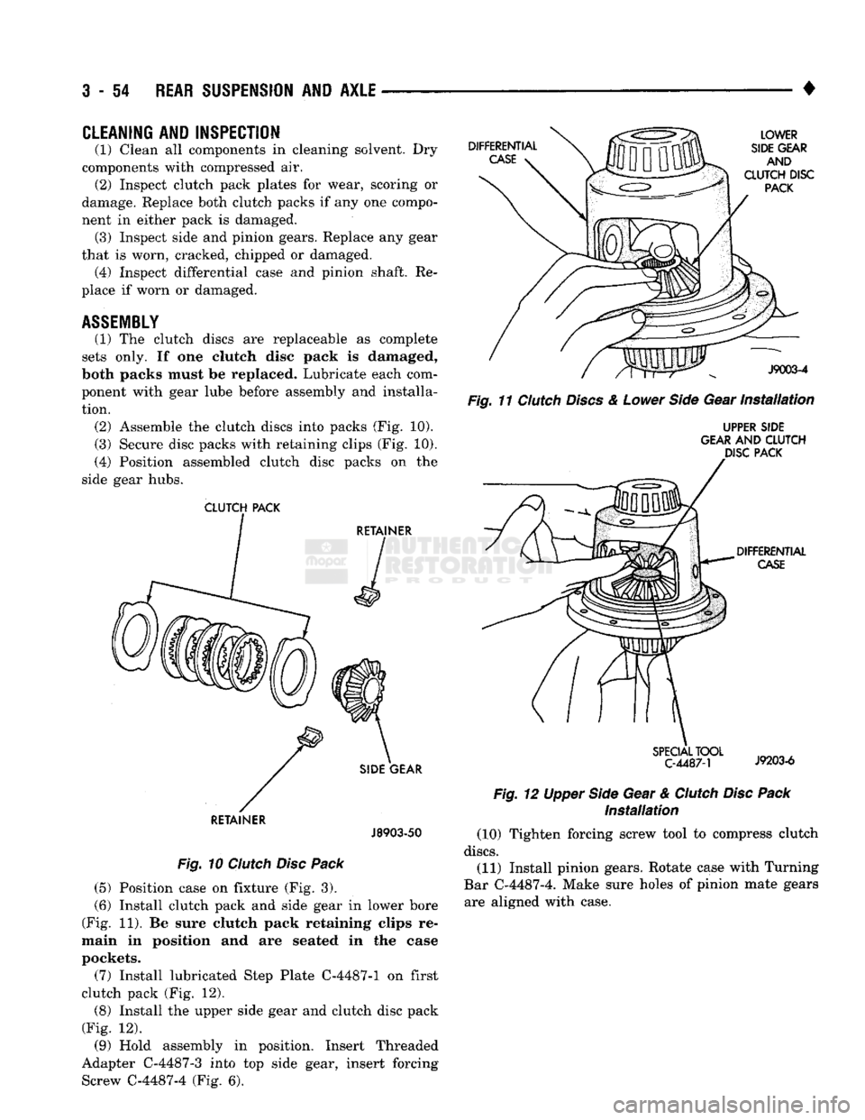
ponent with gear lube before assembly and installa tion. (2) Assemble the clutch discs into packs (Fig. 10).
(3) Secure disc packs with retaining clips (Fig. 10).
(4) Position assembled clutch disc packs on the
side gear hubs.
CLUTCH
PACK
RETAINER
J8903-50
Fig.
10
Clutch
Disc
Pack
(5) Position case on fixture (Fig. 3).
(6) Install clutch pack and side gear in lower bore
(Fig. 11). Be sure clutch pack retaining clips re
main in position and are seated in the case
pockets.
(7) Install lubricated Step Plate C-4487-1 on first
clutch pack (Fig. 12). (8) Install the upper side gear and clutch disc pack
(Fig. 12).
(9) Hold assembly in position. Insert Threaded
Adapter C-4487-3 into top side gear, insert forcing Screw C-4487-4 (Fig. 6).
Fig.
11
Clutch
Discs
&
Lower
Side
Gear
Installation
UPPER SIDE
GEAR AND
CLUTCH
DISC PACK
Installation
(10) Tighten forcing screw tool to compress clutch
discs.
(11) Install pinion gears. Rotate case with Turning
Bar C-4487-4. Make sure holes of pinion mate gears are aligned with case.
Page 182 of 1502
•
REAR
SUSPENSION
AND
AXLE
3 - 55
(12) Tighten forcing screw
to
compress
the
conned
plates.
Lubricate
and
install pinion gear thrust washers with
a
small screw driver.
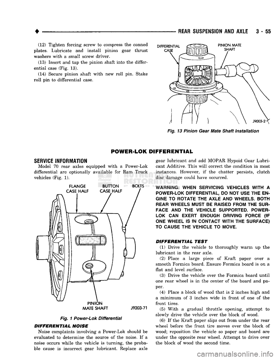
(13) Insert and tap
the
pinion shaft into the differ
ential case (Fig.
13).
(14) Secure pinion shaft with
new
roll pin. Stake
roll
pin
to
differential case.
Fig.
13
Pinion
Gear
Mate
Shaft
installation
POWER-LOK
DIFFERENTIAL
SERVICE
INFORMATION Model
70
rear axles equipped with
a
Power-Lok
differential
are
optionally available
for
Ram
Truck
vehicles (Fig.
1).
FLANGE
BUTTON
BOLTS
PINION
AAATE
SHAFT
J9203-71
Fig.
1
Power-Lok
Differential
DIFFERENTIAL
NOISE
Noise complaints involving
a
Power-Lok should
be
evaluated
to
determine
the
source
of
the noise.
If a
noise occurs while
the
vehicle
is
turning,
the
proba
ble cause
is
incorrect gear lubricant. Replace axle gear lubricant
and add
MOPAR Hypoid Gear Lubri
cant Additive. This will correct the condition
in
most
instances. However,
if the
chatter persists, clutch
disc damage could have occurred.
WARNING:
WHEN SERVICING VEHICLES
WITH
A
POWER-LOK
DIFFERENTIAL, DO NOT USE THE EN
GINE
TO
ROTATE THE AXLE AND
WHEELS.
BOTH
REAR
WHEELS MUST BE
RAISED
FROM THE
SUR
FACE
AND
THE
VEHICLE SUPPORTED. POWER-
LOK
CAN
EXERT ENOUGH DRIVING FORCE
(IF
ONE
WHEEL IS
IN
CONTACT
WITH
THE SURFACE)
TO
CAUSE
THE VEHICLE TO MOVE.
DIFFERENTIAL
TEST
(1) Drive
the
vehicle
to
thoroughly warm
up the
lubricant
in
the
rear axle.
(2) Place
a
large piece
of
Kraft paper over
a
smooth Formica board. Ensure Formica board
is on a
flat and level surface.
(3) Drive
the
vehicle over
the
Formica board until
one rear wheel
is in the
center
of
the board
and
pa
per. (4) Place
a
block
of
wood that
is 2
inches high
and
a minimum
of 3
inches wide
in
front
of
one
of
the
front tires.
(5) With
a
gradual throttle opening, attempt
to
slowly drive
the
vehicle over
the
block
of
wood.
(6)
If
the Kraft paper slips out from under the rear
wheel before
the
front tire moves over
the
block
of
wood; reposition
the
vehicle
so
paper
and
board
are
under
the
opposite rear wheel. Attempt
to
drive over
the block
of
wood
the
second time.
Page 183 of 1502
3
- 56
REAR SUSPENSION
AND
AXLE
CLUTCH
PLATES
J9203-72
BUTTON
HALF
FLANGE
HALF
Fig.
2
Case
Marked
(7)
If the front wheel moves over the block of wood,
the axle can be considered to be functioning normally.
LUBRICANTS
The lubricant recommended for Power-Lok differ
ential is API grade GL 5. A container of Trac-Lok
Lubricant (friction modifier) should be added after
service. Refer to Group 0, Lubrication and Maintenance for
additional information.
FLANGE
HALF
CLUTCH
RING
J9203-73
Fig.
3
Cover
Half
Removal
DISASSEMBLY
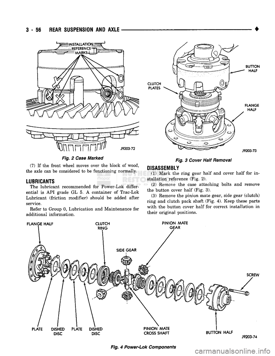
(1) Mark the ring gear half and cover half for in
stallation reference (Fig. 2). (2) Remove the case attaching bolts and remove
the button cover half (Fig. 3). (3) Remove the pinion mate gear, side gear (clutch)
ring and clutch pack shaft (Fig. 4). Keep these parts with the button cover half for correct installation in
their original positions.
PINION MATE
GEAR
SCREW
PLATE
DISHED
DISC
PLATE
DISHED
DISC PINION AAATE
CROSS
SHAFT
BUTTON HALF
J9203-74
Fig.
4
Power-Lok
Components