1993 DODGE TRUCK clutch
[x] Cancel search: clutchPage 268 of 1502
•
CLUTCH
6 - 15
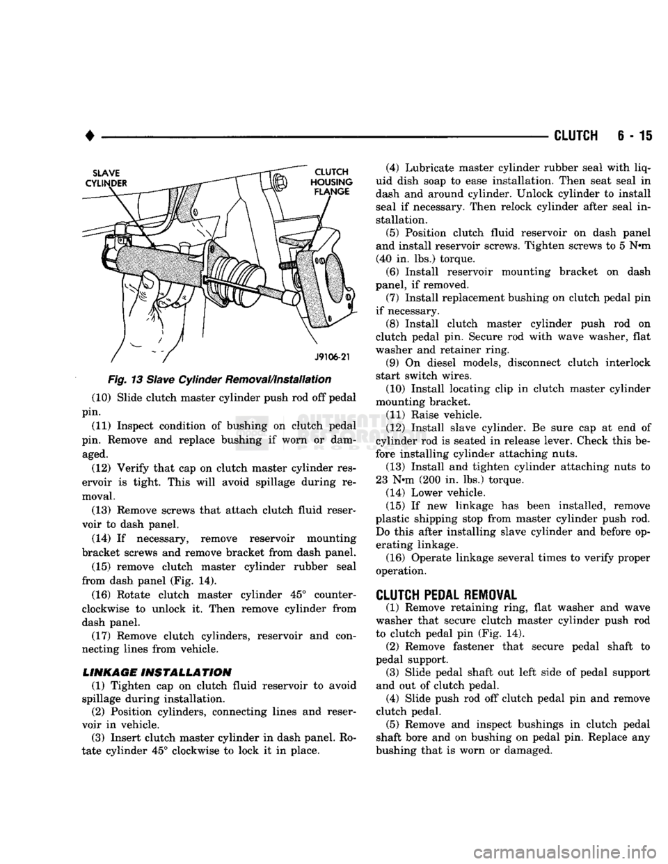
Fig.
13
Slave
Cylinder Removal/Installation (10) Slide clutch master cylinder push rod off pedal
pin.
(11) Inspect condition of bushing on clutch pedal
pin. Remove and replace bushing if worn or dam aged.
(12) Verify that cap on clutch master cylinder res
ervoir is tight. This will avoid spillage during re
moval.
(13) Remove screws that attach clutch fluid reser
voir to dash panel.
(14) If necessary, remove reservoir mounting
bracket screws and remove bracket from dash panel.
(15) remove clutch master cylinder rubber seal
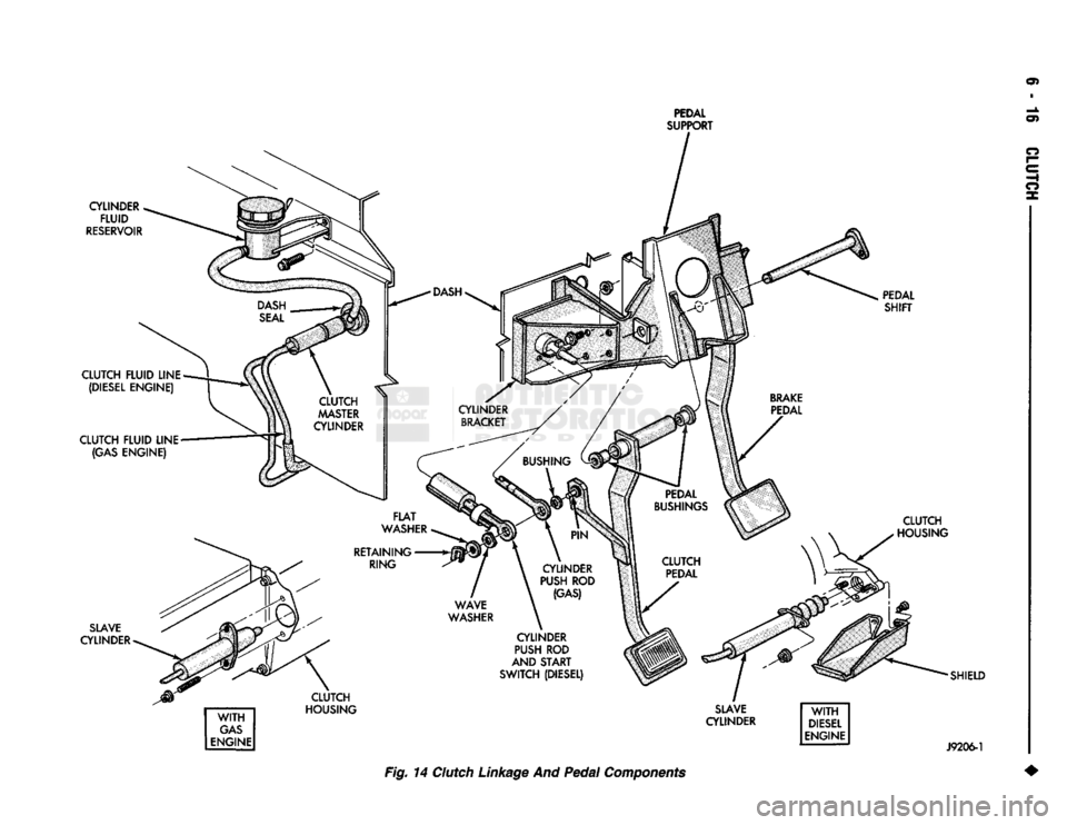
from dash panel (Fig. 14).
(16) Rotate clutch master cylinder 45° counter
clockwise to unlock it. Then remove cylinder from
dash panel. (17) Remove clutch cylinders, reservoir and con
necting lines from vehicle.
LINKAGE
INSTALLATION
(1) Tighten cap on clutch fluid reservoir to avoid
spillage during installation. (2) Position cylinders, connecting lines and reser
voir in vehicle.
(3) Insert clutch master cylinder in dash panel. Ro
tate cylinder 45° clockwise to lock it in place. (4) Lubricate master cylinder rubber seal with liq
uid dish soap to ease installation. Then seat seal in
dash and around cylinder. Unlock cylinder to install
seal if necessary. Then relock cylinder after seal in stallation.
(5) Position clutch fluid reservoir on dash panel
and install reservoir screws. Tighten screws to 5 N»m (40 in. lbs.) torque.
(6) Install reservoir mounting bracket on dash
panel, if removed.
(7) Install replacement bushing on clutch pedal pin
if necessary. (8) Install clutch master cylinder push rod on
clutch pedal pin. Secure rod with wave washer, flat
washer and retainer ring.
(9) On diesel models, disconnect clutch interlock
start switch wires.
(10) Install locating clip in clutch master cylinder
mounting bracket.
(11) Raise vehicle.
(12) Install slave cylinder. Be sure cap at end of
cylinder rod is seated in release lever. Check this be
fore installing cylinder attaching nuts. (13) Install and tighten cylinder attaching nuts to
23 N*m (200 in. lbs.) torque.
(14) Lower vehicle.
(15) If new linkage has been installed, remove
plastic shipping stop from master cylinder push rod. Do this after installing slave cylinder and before operating linkage.
(16) Operate linkage several times to verify proper
operation.
CLUTCH
PEDAL REMOVAL
(1) Remove retaining ring, flat washer and wave
washer that secure clutch master cylinder push rod
to clutch pedal pin (Fig. 14). (2) Remove fastener that secure pedal shaft to
pedal support. (3) Slide pedal shaft out left side of pedal support
and out of clutch pedal. (4) Slide push rod off clutch pedal pin and remove
clutch pedal. (5) Remove and inspect bushings in clutch pedal
shaft bore and on bushing on pedal pin. Replace any
bushing that is worn or damaged.
Page 269 of 1502
en
PEDAL
SUPPORT
CYLINDER FLUID
RESERVOIR
PEDAL SHIFT
CLUTCH FLUID LINE (DIESEL ENGINE)
CLUTCH FLUID LINE (GAS ENGINE)
SLAVE
CYLINDER O
I—
e HI
O
x CLUTCH
HOUSING
WITH
GAS
ENGINE CLUTCH
HOUSING
SLAVE
CYLINDER
WITH
DIESEL
ENGINE SHIELD
J9206-1
Fig. 14
Clutch
Linkage
And
Pedal
Components
Page 270 of 1502

•
CLUTCH
6-17
CLUTCH PEDAL INSTALLATION
(1) Lubricate pedal shaft, pedal shaft bore and all
bushings with Mopar Multi Mileage grease. (2) Insert pedal pin into cylinder push rod. Then
position clutch pedal in support. (3) Slide pedal shaft through clutch pedal bore and
bushings. (4) Install bolt that retains pedal shaft in support.
(5) Secure push rod to pedal pin with wave washer,
flat washer and retaining ring.
FLYWHEEL SERVICE
Inspect the flywheel whenever the clutch disc,
cover and housing are removed for service. Check
condition of the flywheel face, hub, ring gear teeth,
and flywheel bolts. Minor scratches, burrs, or glazing on the flywheel
face can be scuff sanded with 180 grit emery cloth. However, the flywheel should be replaced if the disc
contact surface is severely scored, heat checked,
cracked, or obviously worn. Cleanup of minor flywheel scoring should be per
formed with surface grinding equipment. Remove
only enough material to reduce scoring (approximate
ly 0.001 - 0.003 in.). Heavy stock removal is not rec
ommended. Replace the flywheel if scoring is severe
and deeper than 0.076 mm (0.003 in.). Excessive
stock removal can result in flywheel cracking or
warpage after installation; it can also weaken the flywheel and interfere with proper clutch release. Check flywheel runout if misalignment is sus
pected. Runout should not exceed 0.08 mm (0.003
in.).
Measure runout at the outer edge of the fly
wheel face with a dial indicator. Mount the dial in
dicator on a stud installed in place of one of the
flywheel attaching bolts. Clean the crankshaft flange before mounting the
flywheel. Dirt and grease on the flange surface may cock the flywheel causing excessive runout. Check condition of the flywheel hub and attaching
bolts.
Replace the flywheel if the hub exhibits cracks in the area of the attaching bolt holes. Install new attaching bolts whenever the flywheel
is replaced and use Mopar Lock N' Seal, or Loctite
242 on replacement bolt threads.
Recommended flywheel bolt torques are:
• 75 N»m (55 ft. lbs.) for gas engine flywheels
• 137 N*m (101 ft. lbs.) for diesel flywheels Inspect the teeth on the starter ring gear. If the
teeth are worn or damaged, the flywheel should
be replaced as an assembly. This is the recom mended and preferred method of repair.
In cases where a new flywheel is not readily avail
able,
a replacement ring gear can be installed. How
ever, the following precautions must be observed to
avoid damaging the flywheel and replacement gear.
(a) Mark position of the old gear for alignment
reference on the flywheel. Use a scriber for this
purpose.
(b) Wear protective goggles or approved safety
glasses. Also wear heat resistent gloves when han
dling a heated ring gear. (c) Remove the old gear by cutting most of the
way through it (at one point) with an abrasive cut off wheel. Then complete removal with a cold chisel
or punch. (d) The ring gear is a shrink fit on the flywheel.
This means the gear must be expanded by heating in order to install it. The method of heating and expanding the gear is extremely important. Ev
ery surface of the gear must be heated at the same
time to produce uniform expansion. An oven or
similar enclosed heating device must be used. Tem
perature required for uniform expansion is 325-350° F.
CAUTION:
Never
use an
oxy/acetylene torch
to re
move
the old
gear,
or to
heat
and
expand
a new
gear.
The
high temperature
of the
torch flame
will
cause
localized heating
and
damage
the
flywheel.
In
addition,
using
the
torch
to
heat
a
replacement gear
will
cause uneven heating
and
expansion.
The
torch
flame
will
also
anneal
the
gear
teeth
resulting
in
rapid wear
and
damage
after
installation.
(e) The heated gear must be installed evenly to
avoid misalignment or distortion. A shop press and
suitable press plates should be used to install the
gear if at all possible.
(f) Be sure to wear eye and hand protection.
Heat resistent gloves and safety goggles are needed
for personal safety. Also use metal tongs, vise
grips,
or similar tools to position the gear as necessary for installation.
(g) Allow the flywheel and ring gear to cool
down before installation. Set the assembly on a
workbench and let it cool in normal shop air.
CAUTION:
Do not
use water,
or
compressed
air to
cool
the
flywheel.
The
rapid cooling produced
by
water
or
compressed
air can
distort,
or
crack
the
gear
and
flywheel.
Page 309 of 1502
7 - 38
COOLING
SYSTEM
•
WARNING:
DO NOT
ATTEMPT
TO
BEND
OR
STRAIGHTEN
FAN
BLADES
IF
NOT WITHIN
SPECI
FICATIONS.
(4) Inspect fan assembly for cracks, bends, loose
rivets or broken welds. Replace fan if any damage is
found.
CAUTION; If the fan
blade assembly
is
replaced
be
cause
of
mechanical damage,
the fan
pulley
and
viscous
fan
drive should also
be
inspected.
These
components
could have been damaged
due to ex
cessive
vibration.
INSTALLATION
(1) Install fan blade assembly to viscous fan drive.
Tighten mounting bolts.
(2) Position the fan shroud and fan blade/viscous
fan drive to the vehicle as an assembly.
(3) Install viscous fan drive assembly on fan hub
shaft. Tighten mounting nut to 57 N*m (42 ft. lbs.)
torque.
(4) Install fan shroud bolts.
(5) Install battery cable to battery.
VISCOUS
FAN
DRIVE
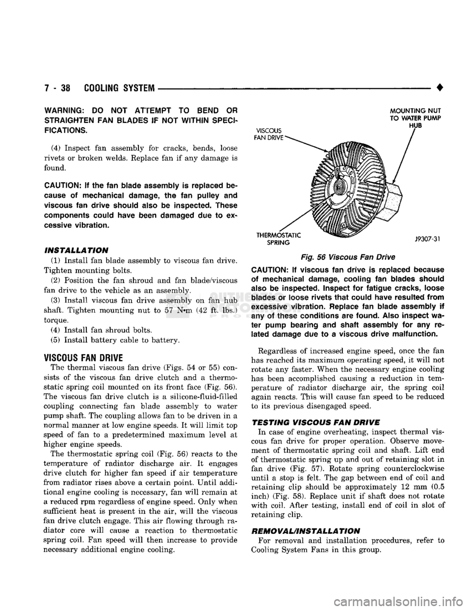
The thermal viscous fan drive (Figs. 54 or 55) con
sists of the viscous fan drive clutch and a thermo
static spring coil mounted on its front face (Fig. 56).
The viscous fan drive clutch is a silicone-fluid-filled coupling connecting fan blade assembly to water
pump shaft. The coupling allows fan to be driven in a normal manner at low engine speeds. It will limit top
speed of fan to a predetermined maximum level at
higher engine speeds.
The thermostatic spring coil (Fig. 56) reacts to the
temperature of radiator discharge air. It engages drive clutch for higher fan speed if air temperature
from radiator rises above a certain point. Until addi
tional engine cooling is necessary, fan will remain at a reduced rpm regardless of engine speed. Only when
sufficient heat is present in the air, will the viscous
fan drive clutch engage. This air flowing through ra diator core will cause a reaction to thermostatic spring coil. Fan speed will then increase to provide
necessary additional engine cooling.
MOUNTING
NUT
TO WATER PUMP
Fig.
56
Viscous
Fan Drive CAUTION; If
viscous
fan
drive
is
replaced because
of mechanical damage, cooling
fan
blades should
also
be
inspected. Inspect
for
fatigue cracks, loose
blades
or
loose rivets
that
could have resulted
from
excessive
vibration. Replace
fan
blade assembly
if
any
of
these conditions
are
found.
Also
inspect
wa
ter
pump bearing
and
shaft assembly
for any re
lated
damage
due to a
viscous
drive malfunction.
Regardless of increased engine speed, once the fan
has reached its maximum operating speed, it will not
rotate any faster. When the necessary engine cooling
has been accomplished causing a reduction in tem perature of radiator discharge air, the spring coil again reacts. This will cause fan speed to be reduced
to its previous disengaged speed.
TESTING VISCOUS FAN DRIVE In case of engine overheating, inspect thermal vis
cous fan drive for proper operation. Observe move
ment of thermostatic spring coil and shaft. Lift end
of thermostatic spring up and out of retaining slot in
fan drive (Fig. 57). Rotate spring counterclockwise until a stop is felt. The gap between end of coil and
retaining clip should be approximately 12 mm (0.5 inch) (Fig. 58). Replace unit if shaft does not rotate
with coil. After testing, install end of coil in slot of retaining clip.
REMOVAUINSTALLA
TION For removal and installation procedures, refer to
Cooling System Fans in this group.
Page 330 of 1502
•
ELECTRICAL
8A - 9
ENGINE STARTER MOTOR TEST PROCEDURES
GENERAL INFORMATION
The starting system consists of an:
• ignition switch
• starter relay
• park/neutral position switch (automatic transmis sion)
• clutch switch (diesel engine-manual transmission)
• wiring harness
• battery
• starter motor with an integral solenoid. These components form 2 separate circuits. A high
amperage circuit that feeds the starter motor up to
300+ amps-gas engine; 500+ amps-diesel engine,
and a control circuit that operates on less than 20
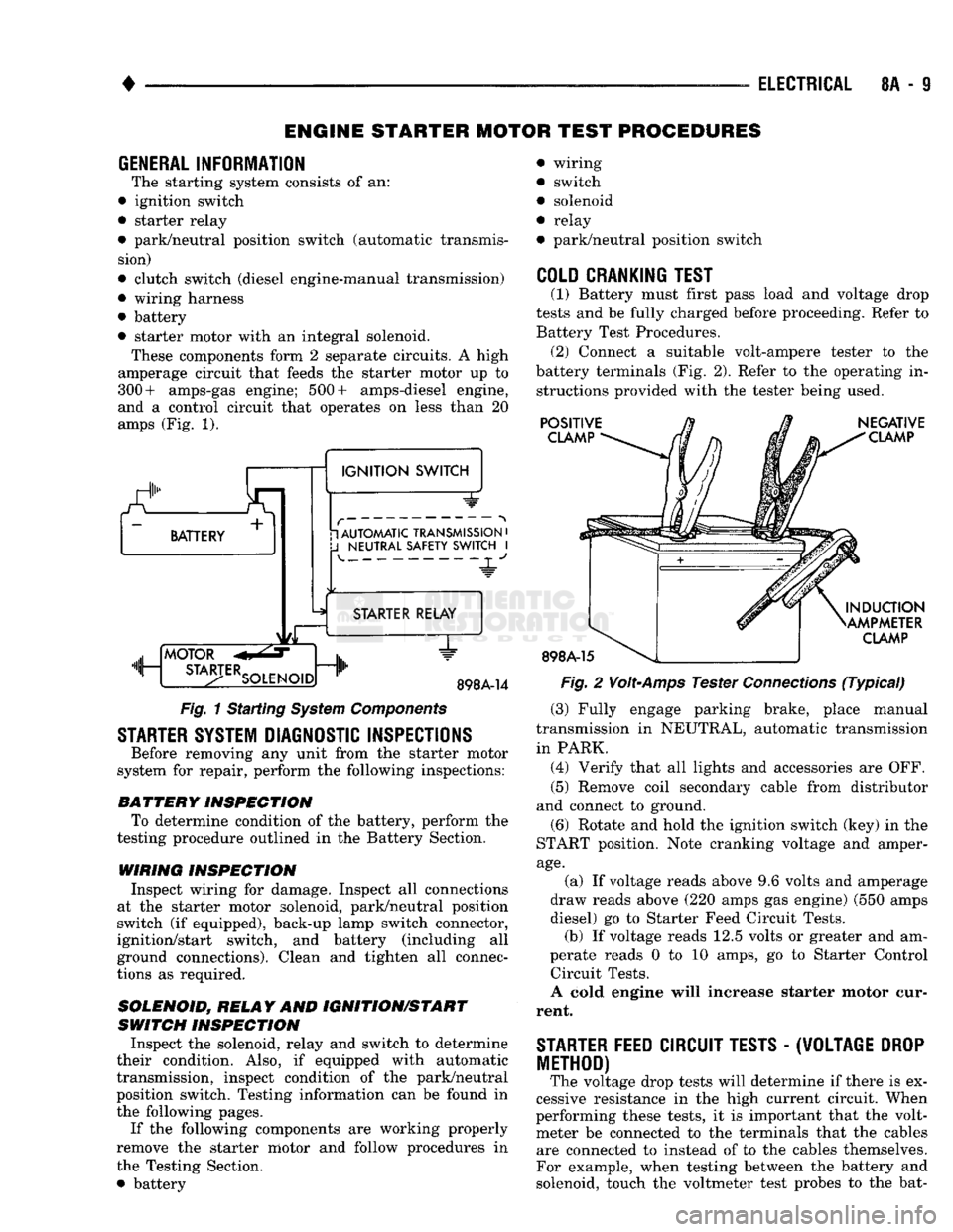
amps (Fig. 1).
a.
BATTERY +
1
IGNITION
SWITCH 1 AUTOMATIC TRANSMISSION
•
J
NEUTRAL SAFETY SWITCH
I 4-
"JL"
MOTOR
m, ...
STA3-TERSOLENO,Dnlh
STARTER RELAY
1"
898A-14
Fig.
1 Starting
System
Components
STARTER SYSTEM DIAGNOSTIC INSPECTIONS
Before removing any unit from the starter motor
system for repair, perform the following inspections:
BATTERY
INSPECTION
To determine condition of the battery, perform the
testing procedure outlined in the Battery Section.
WIRING INSPECTION
Inspect wiring for damage. Inspect all connections
at the starter motor solenoid, park/neutral position
switch (if equipped), back-up lamp switch connector,
ignition/start switch, and battery (including all
ground connections). Clean and tighten all connec
tions as required.
SOLENOID, RELAY
AND
IGNITION/START
SWITCH
INSPECTION
Inspect the solenoid, relay and switch to determine
their condition. Also, if equipped with automatic
transmission, inspect condition of the park/neutral position switch. Testing information can be found in
the following pages.
If the following components are working properly
remove the starter motor and follow procedures in
the Testing Section. • battery wiring
switch
solenoid
relay
park/neutral position switch
COLD CRANKING TEST
(1) Battery must first pass load and voltage drop
tests and be fully charged before proceeding. Refer to Battery Test Procedures. (2) Connect a suitable volt-ampere tester to the
battery terminals (Fig. 2). Refer to the operating in structions provided with the tester being used.
POSITIVE
CLAMP
898A-15
NEGATIVE
CLAMP
INDUCTION
AMPMETER
CLAMP
Fig.
2
Volt-Amps
Tester
Connections
(Typical)
(3) Fully engage parking brake, place manual
transmission in NEUTRAL, automatic transmission
in PARK. (4) Verify that all lights and accessories are OFF. (5) Remove coil secondary cable from distributor
and connect to ground.
(6) Rotate and hold the ignition switch (key) in the
START position. Note cranking voltage and amper
age.
(a) If voltage reads above 9.6 volts and amperage
draw reads above (220 amps gas engine) (550 amps
diesel) go to Starter Feed Circuit Tests. (b) If voltage reads 12.5 volts or greater and am-
perate reads 0 to 10 amps, go to Starter Control Circuit Tests.
A cold engine will increase starter motor cur
rent.
STARTER
FEED
CIRCUIT TESTS
-
(W0LTAGE
DROP
METHOD)
The voltage drop tests will determine if there is ex
cessive resistance in the high current circuit. When
performing these tests, it is important that the volt meter be connected to the terminals that the cables are connected to instead of to the cables themselves.
For example, when testing between the battery and
solenoid, touch the voltmeter test probes to the bat-
Page 331 of 1502
8A
- 10
ELECTRICAL
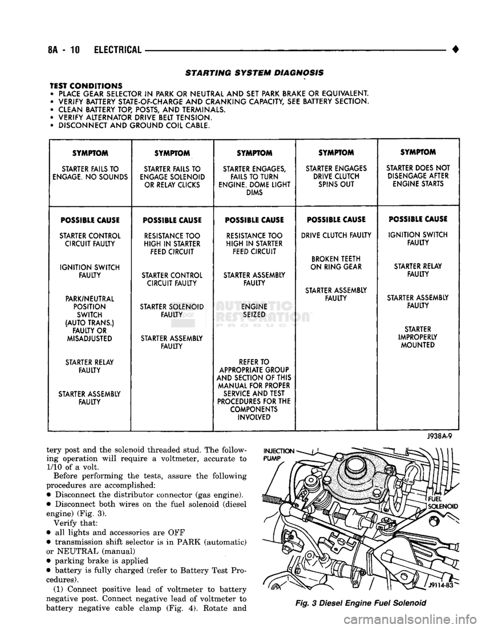
•
STARTING SYSTEM DIAGNOSIS
TEST CONDITIONS • PLACE GEAR SELECTOR
IN
PARK OR NEUTRAL AND SET PARK BRAKE
OR
EQUIVALENT. • VERIFY BATTERY STATE-OF-CHARGE AND CRANKING CAPACITY, SEE BATTERY SECTION.
• CLEAN BATTERY TOP, POSTS, AND TERMINALS.
• VERIFY ALTERNATOR DRIVE BELT TENSION.
• DISCONNECT AND GROUND COIL CABLE. SYMPTOM
SYMPTOM SYMPTOM SYMPTOM SYMPTOM
STARTER FAILS TO STARTER FAILS TO STARTER ENGAGES, STARTER ENGAGES STARTER DOES NOT
ENGAGE.
NO SOUNDS
ENGAGE
SOLENOID FAILS TO TURN DRIVE CLUTCH
DISENGAGE
AFTER
OR RELAY CLICKS ENGINE. DOME
LIGHT
SPINS
OUT
ENGINE STARTS
DIMS
POSSIBLE
CAUSE
POSSIBLE
CAUSE
POSSIBLE
CAUSE
POSSIBLE
CAUSE
POSSIBLE
CAUSE
STARTER CONTROL
RESISTANCE
TOO
RESISTANCE
TOO DRIVE CLUTCH
FAULTY
IGNITION
SWITCH
CIRCUIT
FAULTY
HIGH
IN
STARTER
HIGH
IN
STARTER
FAULTY
FEED CIRCUIT FEED CIRCUIT
BROKEN
TEETH
IGNITION
SWITCH ON RING GEAR
STARTER RELAY
FAULTY
STARTER CONTROL STARTER ASSEMBLY
FAULTY
CIRCUIT
FAULTY FAULTY
STARTER ASSEMBLY
PARK/NEUTRAL
FAULTY
STARTER ASSEMBLY
POSITION STARTER SOLENOID ENGINE
FAULTY
SWITCH
FAULTY
SEIZED
(AUTO
TRANS.) STARTER
FAULTY
OR STARTER
MISADJUSTED STARTER ASSEMBLY IMPROPERLY
FAULTY
MOUNTED
STARTER RELAY
REFER
TO
FAULTY
APPROPRIATE GROUP
AND SECTION OF THIS
MANUAL FOR PROPER
STARTER ASSEMBLY
SERVICE
AND TEST
FAULTY
PROCEDURES
FOR THE
COMPONENTS INVOLVED
J938A-9
tery post and the solenoid threaded stud. The follow
ing operation will require a voltmeter, accurate to 1/10 of a volt.
Before performing the tests, assure the following
procedures are accomplished:
•
Disconnect the distributor connector (gas engine).
•
Disconnect both wires on the fuel solenoid (diesel engine) (Fig. 3). Verify that:
•
all lights and accessories are OFF
•
transmission shift selector is in PARK (automatic)
or NEUTRAL (manual)
•
parking brake is applied
•
battery is fully charged (refer to Battery Test Pro
cedures). (1) Connect positive lead of voltmeter to battery
negative post. Connect negative lead of voltmeter to
battery negative cable clamp (Fig. 4). Rotate and
Fig.
3
Diesel
Engine
Fuel
Solenoid
Page 332 of 1502
•
ELECTRICAL
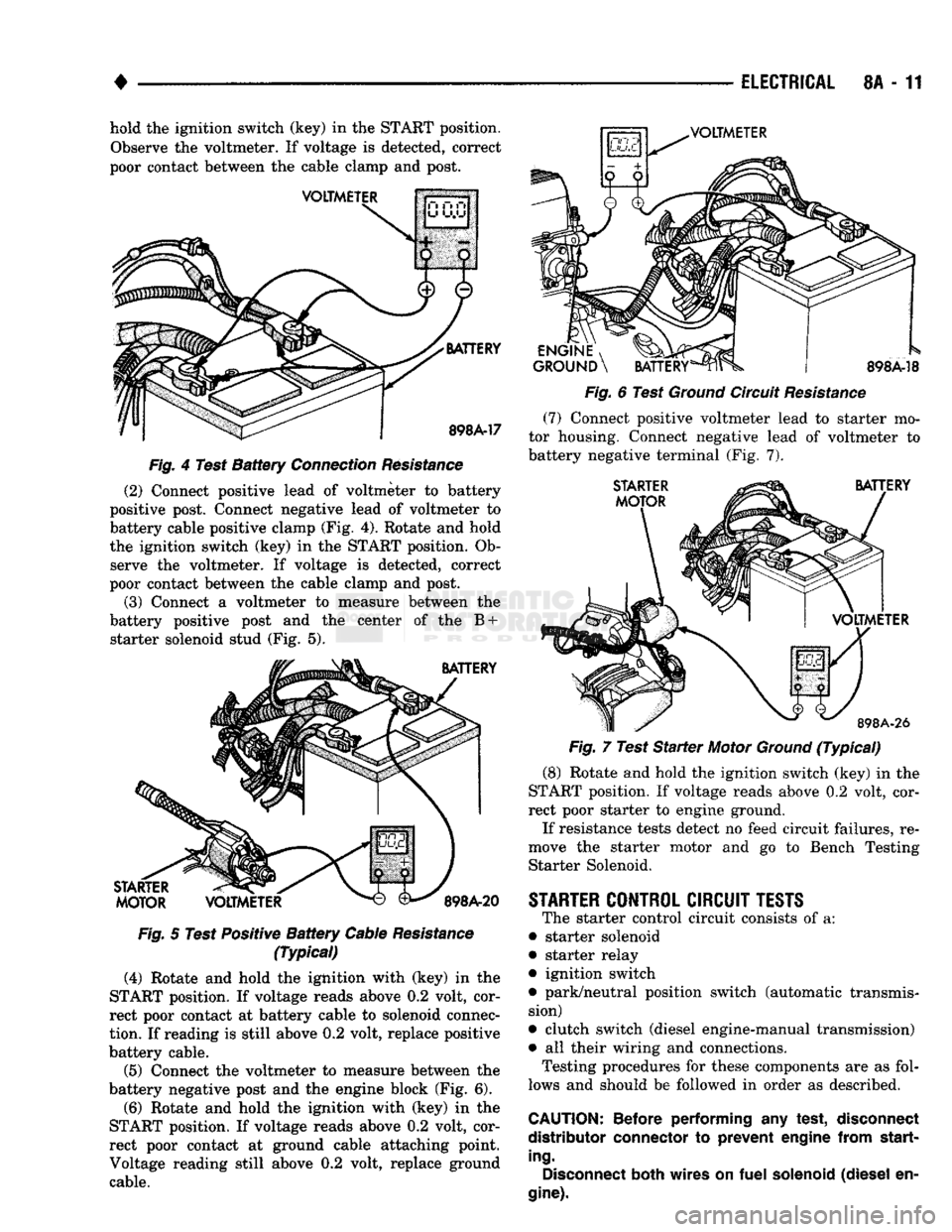
8A - 11 hold the ignition switch (key) in the START position.
Observe the voltmeter. If voltage is detected, correct
poor contact between the cable clamp and post.
VOLTMETER
VOLTMETER
BATTERY
898A-17
Fig.
4 Test
Battery
Connection
Resistance
(2) Connect positive lead of voltmeter to battery
positive post. Connect negative lead of voltmeter to
battery cable positive clamp (Fig. 4). Rotate and hold
the ignition switch (key) in the START position. Ob serve the voltmeter. If voltage is detected, correct
poor contact between the cable clamp and post.
(3) Connect a voltmeter to measure between the
battery positive post and the center of the B + starter solenoid stud (Fig. 5).
BATTERY
STARTER
MOTOR
VOLTMETER
898A-20
Fig.
5 Test Positive
Battery
Cable
Resistance
(Typical)
(4) Rotate and hold the ighition with (key) in the
START position. If voltage reads above 0.2 volt, cor
rect poor contact at battery cable to solenoid connec
tion.
If reading is still above 0.2 volt, replace positive
battery cable.
(5) Connect the voltmeter to measure between the
battery negative post and the engine block (Fig. 6).
(6) Rotate and hold the ignition with (key) in the
START position. If voltage reads above 0.2 volt, cor
rect poor contact at ground cable attaching point.
Voltage reading still above 0.2 volt, replace ground cable.
ENGINE
, ^J^P
GROUND
\
BATTERY
898A-18
Fig.
6 Test
Ground
Circuit
Resistance
(7)
Connect positive voltmeter lead to starter mo
tor housing. Connect negative lead of voltmeter to
battery negative terminal (Fig. 7).
STARTER
MOTOR
BATTERY
VOLTMETER
898A-26
Fig.
7 Test
Starter
Motor
Ground
(Typical)
(8) Rotate and hold the ignition switch (key) in the
START position. If voltage reads above 0.2 volt, cor
rect poor starter to engine ground.
If resistance tests detect no feed circuit failures, re
move the starter motor and go to Bench Testing Starter Solenoid.
STARTER
CONTROL
CIRCUIT
TESTS
The starter control circuit consists of a:
• starter solenoid
• starter relay
• ignition switch
• park/neutral position switch (automatic transmis sion)
• clutch switch (diesel engine-manual transmission)
• all their wiring and connections.
Testing procedures for these components are as fol
lows and should be followed in order as described.
CAUTION:
Before
performing
any
test,
disconnect
distributor
connector
to
prevent
engine
from
start
ing.
Disconnect
both
wires
on
fuel
solenoid
(diesel
en
gine).
Page 333 of 1502
8A
- 12
ELECTRICAL
•
ENGINE
STARTER
RELAY
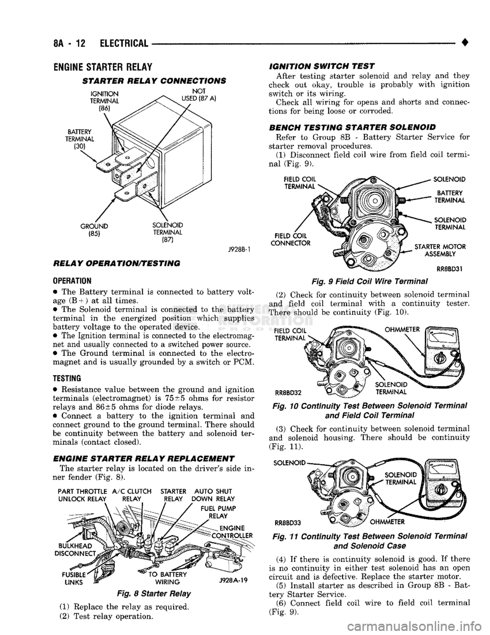
STARTER RELAY CONNECTIONS
GROUND SOLENOID (85) TERMINAL
(87) J928B-1
RELAY OPERATION/TESTING
OPERATION
• The Battery terminal is connected to battery volt
age (B +
)
at all times.
• The Solenoid terminal is connected to the battery
terminal in the energized position which supplies
battery voltage to the operated device. • The Ignition terminal is connected to the electromag
net and usually connected to a switched power source.
• The Ground terminal is connected to the electro
magnet and is usually grounded by a switch or PCM.
TESTING
• Resistance value between the ground and ignition
terminals (electromagnet) is
75
±5 ohms for resistor
relays and 86±5 ohms for diode relays.
• Connect a battery to the ignition terminal and
connect ground to the ground terminal. There should
be continuity between the battery and solenoid ter minals (contact closed).
ENGINE STARTER RELAY REPLACEMENT The starter relay is located on the driver's side in
ner fender (Fig. 8).
PART THROTTLE
A/C
CLUTCH STARTER AUTO SHUT
UNLOCK RELAY RELAY RELAY DOWN RELAY
Fig.
8
Starter
Relay
(1) Replace the relay as required.
(2) Test relay operation. IGNITION SWITCH TEST
After testing starter solenoid and relay and they
check out okay, trouble is probably with ignition
switch or its wiring. Check all wiring for opens and shorts and connec
tions for being loose or corroded.
BENCH TESTING STARTER SOLENOID Refer to Group 8B - Battery Starter Service for
starter removal procedures. (1) Disconnect field coil wire from field coil termi
nal (Fig. 9).
Fig.
9 Field
Coil
Wire
Terminal
(2) Check for continuity between solenoid terminal
and field coil terminal with a continuity tester.
There should be continuity (Fig. 10).
Fig.
10 Continuity Test Between
Solenoid
Terminal
and
Field
Coil
Terminal
(3) Check for continuity between solenoid terminal
and solenoid housing. There should be continuity
(Fig. 11).
SOLENOID
RR8BD33 Fig.
11 Continuity Test Between
Solenoid
Terminal
and Solenoid Case
(4) If there is continuity solenoid is good. If there
is no continuity in either test solenoid has an open
circuit and is defective. Replace the starter motor. (5) Install starter as described in Group 8B - Bat
tery Starter Service. (6) Connect field coil wire to field coil terminal
(Fig. 9).