1993 DODGE TRUCK clutch
[x] Cancel search: clutchPage 260 of 1502
CLUTCH
6 - 7
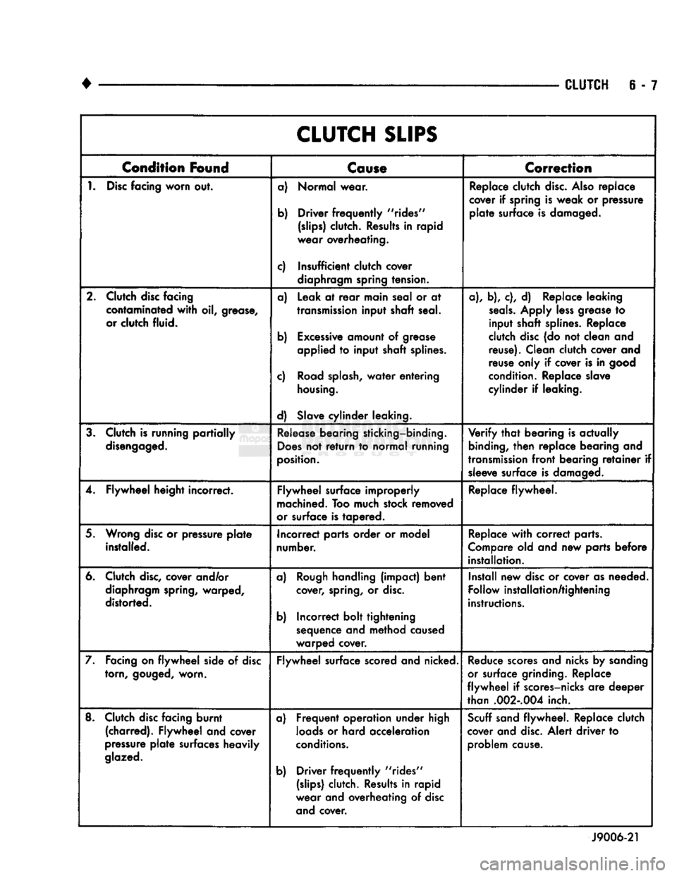
CLUTCH
SLIPS
Condition
Found
Cause
Correction
1.
Disc
facing
worn
out. a) Normal wear.
b) Driver
frequently
"rides"
(slips)
clutch. Results in rapid
wear overheating.
c) Insufficient clutch cover diaphragm spring tension. Replace clutch
disc.
Also
replace
cover if spring is weak or pressure
plate
surface is damaged.
2. Clutch disc facing contaminated
with
oil, grease,
or clutch fluid. a) Leak at
rear
main seal or at
transmission
input shaft seal.
b) Excessive amount of grease applied to input shaft splines.
c) Road
splash,
water
entering
housing.
d) Slave cylinder leaking. a), b), c), d) Replace leaking
seals.
Apply
less
grease to
input shaft splines. Replace
clutch disc (do not clean and reuse). Clean clutch cover and
reuse only if cover is in good
condition. Replace slave
cylinder if leaking.
3. Clutch is running
partially
disengaged.
Release
bearing sticking-binding.
Does
not
return
to normal running
position.
Verify
that
bearing is actually
binding,
then
replace bearing and
transmission
front
bearing
retainer
if sleeve surface is damaged.
4. Flywheel height incorrect. Flywheel surface improperly
machined. Too much stock removed
or surface is tapered. Replace flywheel.
5. Wrong disc or pressure
plate
installed. Incorrect parts order or model
number. Replace
with
correct parts.
Compare old and new parts before installation.
6. Clutch
disc,
cover and/or diaphragm spring, warped,
distorted. a)
Rough
handling (impact) bent
cover, spring, or
disc.
b) Incorrect bolt tightening sequence and method caused
warped cover. Install new disc or cover as needed.
Follow installation/tightening
instructions.
7. Facing on
flywheel
side of disc torn,
gouged,
worn. Flywheel surface scored and nicked.
Reduce
scores and nicks by sanding
or surface grinding. Replace
flywheel
if scores-nicks are deeper
than
.002-.004
inch.
8. Clutch disc facing burnt (charred). Flywheel and cover
pressure
plate
surfaces heavily
glazed.
a) Frequent operation under high
loads
or hard acceleration
conditions.
b) Driver
frequently
"rides"
(slips)
clutch. Results in rapid
wear and overheating of disc and cover.
Scuff
sand flywheel. Replace clutch
cover and
disc.
Alert driver to problem cause.
J9006-21
Page 261 of 1502
6
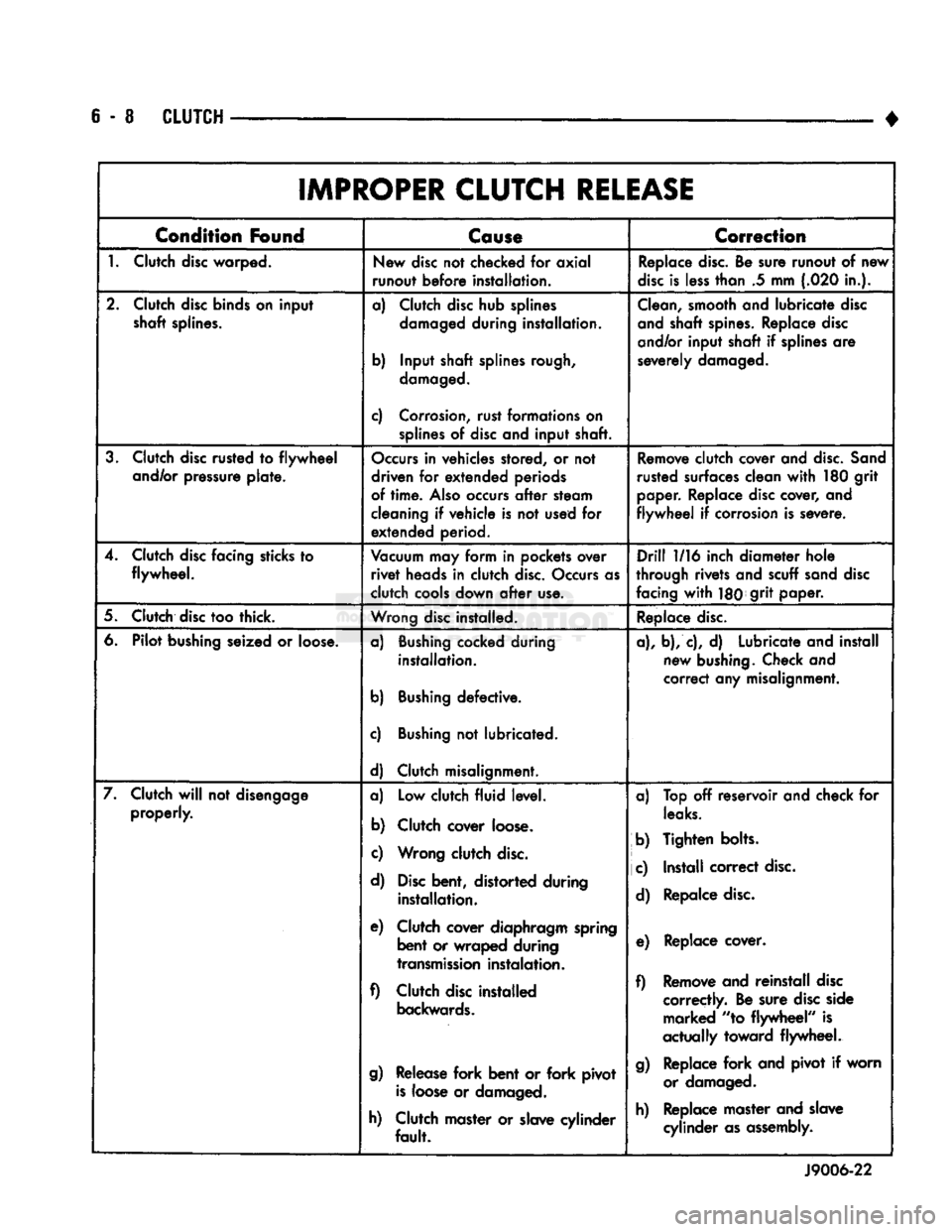
- 8
CLUTCH
IMPROPER CLUTCH
RELEASE
Condition
Found
Cause
Correction
1.
Clutch disc warped. New disc not checked for axial
runout before installation. Replace
disc.
Be sure runout of new
disc
is
less
than .5 mm (.020 in.).
2. Clutch disc binds on input shaft splines. a) Clutch disc hub splines
damaged
during installation.
b) Input shaft splines rough,
damaged.
c) Corrosion, rust formations on
splines
of disc and input shaft.
Clean,
smooth and lubricate disc
and shaft spines. Replace disc
and/or input shaft if splines are
severely damaged.
3. Clutch disc rusted to
flywheel
and/or pressure plate.
Occurs
in vehicles stored, or not
driven for extended periods
of
time.
Also
occurs
after
steam
cleaning if vehicle is not used for extended period.
Remove
clutch cover and
disc.
Sand
rusted surfaces clean
with
180 grit
paper. Replace disc cover, and
flywheel
if corrosion is severe.
4. Clutch disc facing sticks to flywheel.
Vacuum
may form in pockets over
rivet
heads in clutch
disc.
Occurs as
clutch cools down
after
use.
Drill
1/16 inch diameter hole
through rivets and scuff sand disc
facing
with
180J
9r>t
paper.
5. Clutch disc too thick.
Wrong
disc installed. Replace
disc.
6. Pilot bushing seized or loose. a) Bushing cocked during
installation.
b) Bushing defective.
c) Bushing not lubricated.
d) Clutch misalignment. a), b), c), d) Lubricate and install
new bushing. Check and
correct any misalignment.
7. Clutch
will
not disengage properly. a) Low clutch fluid level.
b) Clutch cover loose.
c) Wrong clutch
disc.
d)
Disc
bent, distorted during installation.
e) Clutch cover diaphragm spring bent or wraped during
transmission
instalation.
f) Clutch disc installed
backwards.
g)
Release fork bent or fork pivot
is
loose or damaged.
h) Clutch master or slave cylinder
fault.
a) Top off reservoir and check for
leaks.
b) Tighten bolts.
|
c) Install correct
disc.
d) Repalce
disc.
e) Replace cover.
f) Remove and reinstall disc correctly. Be sure disc side marked "to flywheel" is
actually toward flywheel.
g)
Replace
fork
and pivot if worn or damaged.
h) Replace master and slave cylinder as assembly.
J9006-22
Page 262 of 1502
•
CLUTCH
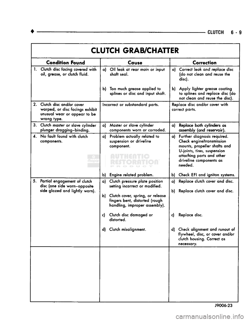
6 - 9 CLUTCH GRAB/CHATTER
Condition
Found
Cause
T
Correction
1.
Clutch
disc
facing covered
with
oil, grease, or clutch fluid. a) Oil leak at
rear
main or input
shaft seal.
b) Too much grease applied to
splines
or
disc
and input shaft. a) Correct leak and replace
disc
(do not clean and reuse the
disc).
b) Apply lighter grease coating to splines and replace
disc
(do not clean and reuse the disc).
2. Clutch
disc
and/or cover warped, or
disc
facings
exhibit
unusual
wear or appear to be
wrong type. Incorrect or substandard parts.
Replace
disc
and/or cover
with
correct parts.
3. Clutch master or slave cylinder plunger dragging-binding. a) Master or slave cylinder
components worn or corroded. a) Replace both cylinders as
assembly
(and reservoir).
4. No
fault
found
with
clutch
components.
a) Problem actually
related
to
suspension
or driveline
component.
b) Engine
related
problem. a)
Further
diagnosis
required.
Check
engine/transmission
mounts,
propeller shafts and U-joints, tires,
suspension
attaching parts and other
driveline components as needed.
b) Check EFI and igniton
systems.
5.
Partial
engagement of clutch
disc
(one side worn-opposite
side
glazed and lightly worn). a) Clutch pressure
plate
position
setting incorrect or modified.
b) Clutch cover, spring, or release fingers bent, distorted (rough
handling,
improper assembly).
c) Clutch
disc
damaged or distorted.
d) Clutch misalignment. a) Replace clutch cover and
disc.
b) Replace clutch cover and
disc.
c) Replace
disc.
d) Check alignment and runout of flywheel,
disc,
or cover and/or clutch
housing.
Correct as
necessary.
J9006-23
Page 263 of 1502
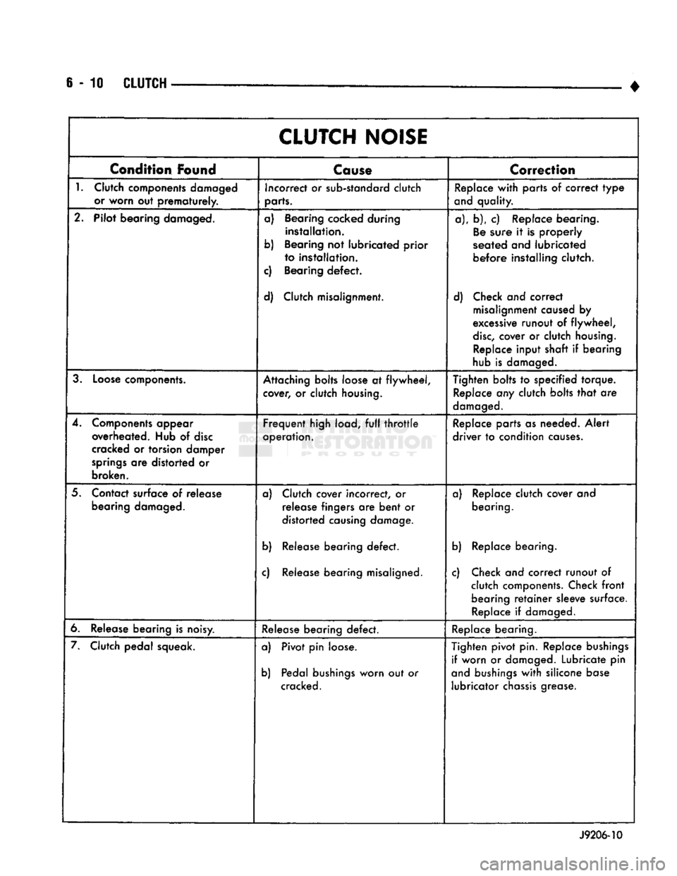
6-10
CLUTCH
•
CLUTCH
NOISE
Condition
Found
Cause
Correction
1.
Clutch components damaged or worn out
prematurely.
Incorrect or sub-standard clutch
parts. Replace
with
parts of correct
type
and quality.
2. Pilot bearing damaged. a) Bearing cocked during
installation.
b) Bearing not lubricated prior to installation.
c) Bearing
defect.
d) Clutch misalignment. a), b), c) Replace bearing.
Be
sure it is properly
seated and lubricated
before
installing clutch.
d) Check and correct misalignment caused by
excessive runout of
flywheel,
disc,
cover or clutch
housing.
Replace input shaft if bearing
hub is damaged.
3.
Loose
components. Attaching bolts loose at
flywheel,
cover, or clutch
housing.
Tighten bolts to specified torque.
Replace any clutch bolts
that
are
damaged.
4. Components appear overheated. Hub of
disc
cracked or torsion damper
springs
are distorted or
broken.
Frequent
high load,
full
throttle
operation. Replace parts as needed.
Alert
driver
to condition
causes.
5. Contact surface of release bearing damaged. a) Clutch cover incorrect, or
release fingers are
bent
or
distorted causing damage.
b) Release bearing
defect.
c) Release bearing misaligned. a) Replace clutch cover and
bearing.
b) Replace bearing.
c) Check and correct runout of clutch components. Check
front
bearing
retainer
sleeve surface. Replace if damaged.
6. Release bearing is noisy. Release bearing
defect.
Replace bearing.
7. Clutch pedal squeak. a) Pivot pin loose.
b) Pedal
bushings
worn out or
cracked. Tighten pivot pin. Replace
bushings
if worn or damaged. Lubricate pin
and
bushings
with
silicone base lubricator
chassis
grease.
J9206-10
Page 264 of 1502
•
CLUTCH
S - 11
CLUTCH
SERVICE
INDEX
page
Clutch
Cover
and
Disc
Installation—All
11
Clutch
Cover
and
Disc
Removal—All
. 11
Clutch
Housing
Installation
13
Clutch
Housing
Removal
12
Clutch
Linkage
Service
14
CLUTCH
COVER
AND
DISC
REMOVAL—ALL
(1) Raise vehicle.
(2) Remove transmission and remove transfer case
if equipped. Refer to Group 21 for procedures. (3) Remove clutch housing from engine.
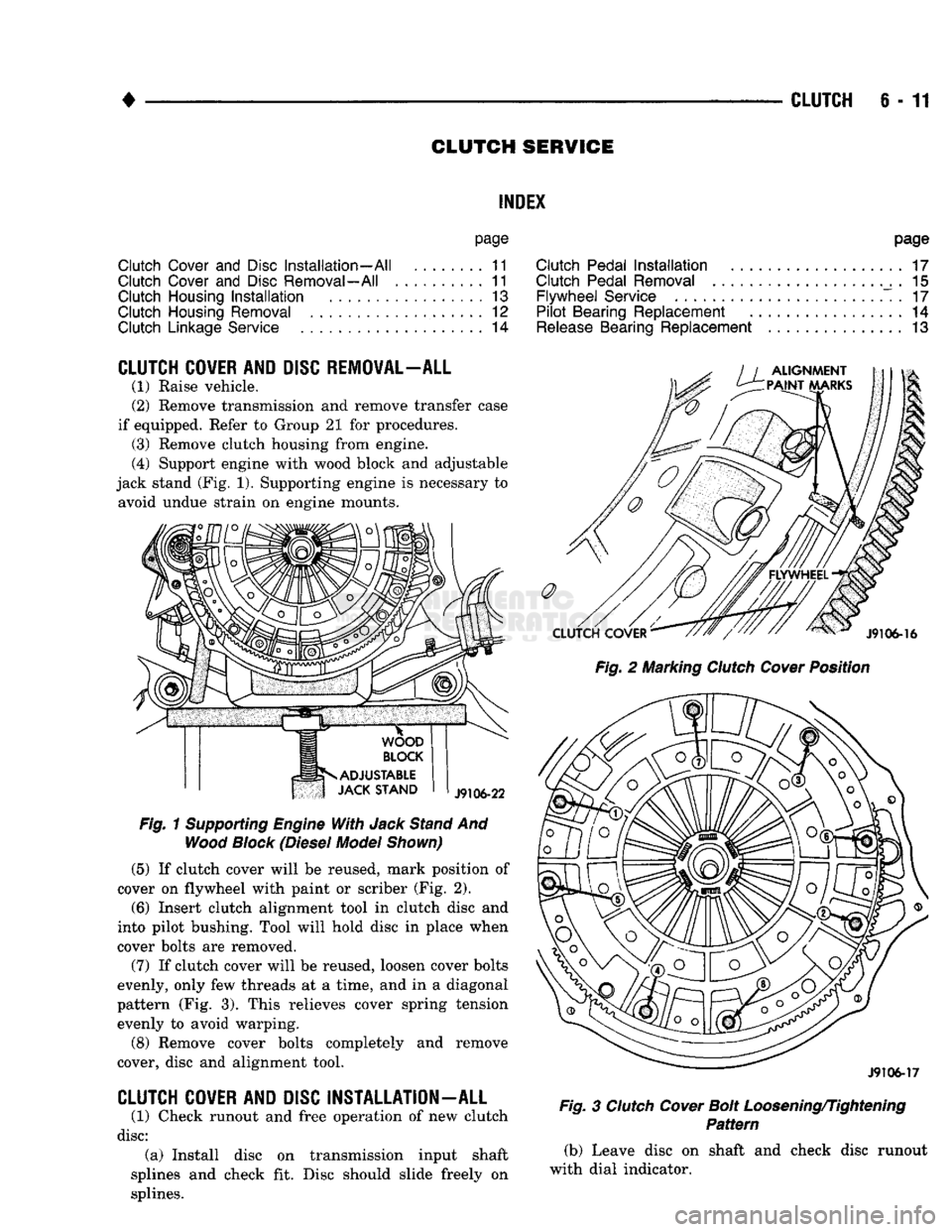
(4) Support engine with wood block and adjustable
jack stand (Fig. 1). Supporting engine is necessary to avoid undue strain on engine mounts.
Fig.
1
Supporting
Engine
With
Jack
Stand
And
Wood
Block
(Diesel
Model
Shown)
(5)
If clutch cover will be reused, mark position of
cover on flywheel with paint or scriber (Fig. 2).
(6)
Insert clutch alignment tool in clutch disc and
into pilot bushing. Tool will hold disc in place when
cover bolts are removed.
(7) If clutch cover will be reused, loosen cover bolts
evenly, only few threads at a time, and in a diagonal
pattern (Fig. 3). This relieves cover spring tension evenly to avoid warping.
(8) Remove cover bolts completely and remove
cover, disc and alignment tool.
CLUTCH
COVER
AND
DISC
INSTALLATION
-
ALL
(1) Check runout and free operation of new clutch
disc:
(a) Install disc on transmission input shaft
splines and check fit. Disc should slide freely on
splines.
page
Clutch
Pedal
Installation
17
Clutch
Pedal
Removal
. 15
Flywheel
Service
. 17
Pilot
Bearing
Replacement
14
Release
Bearing
Replacement
13
Fig.
2 Marking
Clutch
Cover
Position
J9106-17
Fig.
3
Clutch
Cover
Bolt
Loosening/Tightening
Pattern
(b) Leave disc on shaft and check disc runout
with dial indicator.
Page 265 of 1502
6-12
CLUTCH
(c) Position indicator plunger about 1/4 inch from
outer edge of disc facing.
(d) Runout should not exceed 0.5 mm (0.020 in.).
Obtain another clutch disc if runout exceeds this
limit.
(2) Lubricate crankshaft pilot bearing with Mopar
high temperature bearing grease.
(3) Insert clutch alignment tool in clutch disc hub,
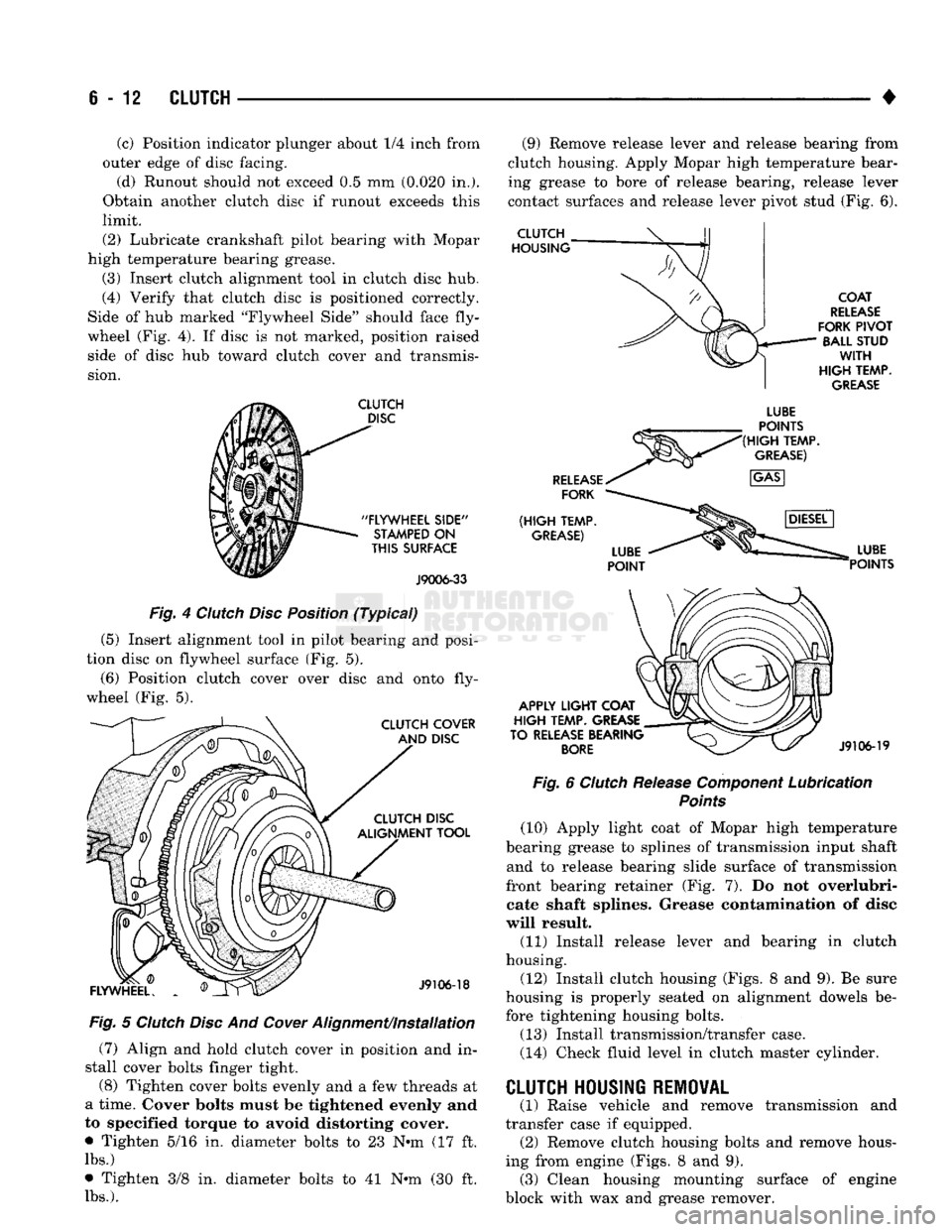
(4) Verify that clutch disc is positioned correctly.
Side of hub marked "Flywheel Side" should face fly
wheel (Fig. 4). If disc is not marked, position raised side of disc hub toward clutch cover and transmis
sion.
CLUTCH
DISC
"FLYWHEEL
SIDE"
STAMPED
ON
THIS
SURFACE
J9006-33
Fig. 4 Clutch Disc Position (Typical)
(5) Insert alignment tool in pilot bearing and posi
tion disc on flywheel surface (Fig. 5).
(6) Position clutch cover over disc and onto fly
wheel (Fig. 5).
CLUTCH COVER AND DISC CLUTCH DISC
ALIGNMENT TOOL
FLYWHEEL.
J9106-18
Fig. 5 Clutch Disc And
Cower
Alignment/installation (7) Align and hold clutch cover in position and in
stall cover bolts finger tight.
(8) Tighten cover bolts evenly and a few threads at
a time. Cover bolts must be tightened evenly and
to specified torque to avoid distorting cover.
• Tighten 5/16 in. diameter bolts to 23 N-m (17 ft.
lbs.)
• Tighten 3/8 in. diameter bolts to 41 N-m (30 ft.
lbs.).
(9) Remove release lever and release bearing from
clutch housing. Apply Mopar high temperature bear
ing grease to bore of release bearing, release lever
contact surfaces and release lever pivot stud (Fig. 6).
CLUTCH
HOUSING
COAT
RELEASE
FORK
PIVOT
BALL STUD
WITH
HIGH
TEMP.
GREASE
RELEASE
FORK
(HIGH
TEMP.
GREASE)
LUBE
POINTS
(HIGH
TEMP.
GREASE)
APPLY
LIGHT
COAT
HIGH
TEMP. GREASE
TO RELEASE BEARING
BORE
LUBE
POINTS
J9106-19
Fig. 6 Clutch Release Component Lubrication
Points
(10) Apply light coat of Mopar high temperature
bearing grease to splines of transmission input shaft and to release bearing slide surface of transmission
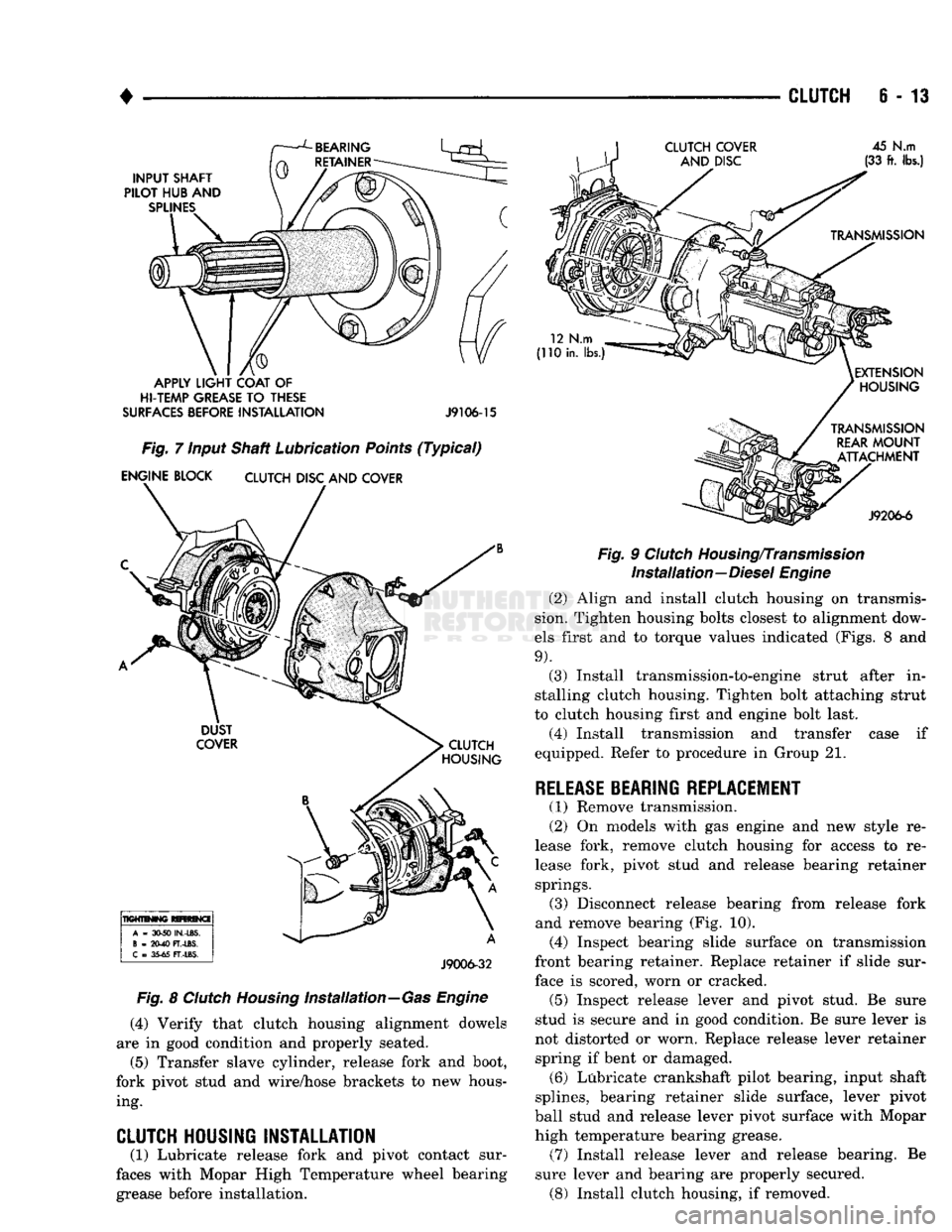
front bearing retainer (Fig. 7). Do not overlubri- cate shaft splines. Grease contamination of disc
will result. (11) Install release lever and bearing in clutch
housing.
(12) Install clutch housing (Figs. 8 and 9). Be sure
housing is properly seated on alignment dowels be fore tightening housing bolts.
(13) Install transmission/transfer case.
(14) Check fluid level in clutch master cylinder. transmission and
CLUTCH HOUSING REMOVAL
(1) Raise vehicle and remove
transfer case if equipped. (2) Remove clutch housing bolts and remove hous
ing from engine (Figs. 8 and 9). (3) Clean housing mounting surface of engine
block with wax and grease remover.
Page 266 of 1502
•
CLUTCH
6 - 13
APPLY
LIGHT
COAT
OF
HI-TEMP
GREASE
TO
THESE
SURFACES
BEFORE
INSTALLATION
J9106-15
Fig.
7 Input Shaft Lubrication
Points
(Typical)
ENGINE BLOCK
CLUTCH
DISC AND COVER
J9006-32
Fig.
8
Clutch
Housing
Installation—Gas
Engine
(4)
Verify that clutch housing alignment dowels
are in good condition and properly seated. (5) Transfer slave cylinder, release fork and boot,
fork pivot stud and wire/hose brackets to new hous ing.
CLUTCH HOUSING INSTALLATION
(1) Lubricate release fork and pivot contact sur
faces with Mopar High Temperature wheel bearing grease before installation.
Fig.
9
Clutch
Housing/Transmission
Installation—Diesel
Engine
(2) Align and install clutch housing on transmis
sion. Tighten housing bolts closest to alignment dow
els first and to torque values indicated (Figs. 8 and
9).
(3) Install transmission-to-engine strut after in
stalling clutch housing. Tighten bolt attaching strut
to clutch housing first and engine bolt last.
(4) Install transmission and transfer case if
equipped. Refer to procedure in Group 21.
RELEASE
BEARING REPLACEMENT
(1) Remove transmission.
(2) On models with gas engine and new style re
lease fork, remove clutch housing for access to re
lease fork, pivot stud and release bearing retainer springs. (3) Disconnect release bearing from release fork
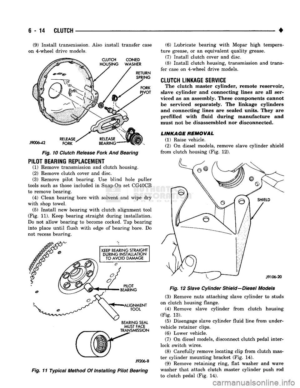
and remove bearing (Fig. 10). (4) Inspect bearing slide surface on transmission
front bearing retainer. Replace retainer if slide sur face is scored, worn or cracked. (5) Inspect release lever and pivot stud. Be sure
stud is secure and in good condition. Be sure lever is
not distorted or worn. Replace release lever retainer spring if bent or damaged. (6) Lubricate crankshaft pilot bearing, input shaft
splines, bearing retainer slide surface, lever pivot
ball stud and release lever pivot surface with Mopar
high temperature bearing grease. (7) Install release lever and release bearing. Be
sure lever and bearing are properly secured. (8) Install clutch housing, if removed.
Page 267 of 1502
6
- 14
CLUTCH
(9) Install transmission. Also install transfer case
on 4-wheel drive models.
Fig.
10
Clutch
Release
Fork
And Bearing
PILOT BEARING REPLACEMENT
(1) Remove transmission and clutch housing.
(2) Remove clutch cover and disc.
(3) Remove pilot bearing. Use blind hole puller
tools such as those included in Snap-On set CG40CB
to remove bearing. (4) Clean bearing bore with solvent and wipe dry
with shop towel. (5) Install new bearing with clutch alignment tool
(Fig. 11). Keep bearing straight during installation.
Do not allow bearing to become cocked. Tap bearing
into place until flush with edge of bearing bore. Do
not recess bearing.
BEARING SEAL
MUST
FACE
J9206-8
Fig.
11 Typical Method Of Installing Pilot Bearing (6) Lubricate bearing with Mopar high tempera
ture grease, or an equivalent quality grease.
(7) Install clutch cover and disc.
(8) Install clutch housing, transmission and trans
fer case on 4-wheel drive models.
CLUTCH LINKAGE SERVICE
The clutch master cylinder, remote reservoir,
slave cylinder and connecting lines are all ser
viced as an assembly. These components cannot
be serviced separately. The linkage cylinders and connecting lines are sealed units. They are
prefilled with fluid during manufacture and
must not be disassembled nor disconnected.
LINKAGE REMOVAL
(1) Raise vehicle.
(2) On diesel models, remove slave cylinder shield
from clutch housing (Fig. 12).
Fig.
12
Slave
Cylinder
Shield—Diesel
Models
(3) Remove nuts attaching slave cylinder to studs
on clutch housing flange.
(4) Remove slave cylinder from clutch housing
(Fig. 13). (5) Disengage slave cylinder fluid line from under-
vehicle retainer clips. (6) Lower vehicle.
(7) On diesel models, disconnect clutch pedal inter
lock switch wires.
(8) Carefully remove locating clip from clutch mas
ter cylinder mounting bracket (Fig. 14). (9) Remove retaining ring, flat washer and wave
washer that attach clutch master cylinder push rod
to clutch pedal (Fig. 14).