1993 DODGE TRUCK clutch
[x] Cancel search: clutchPage 345 of 1502
8B
- 4
BATTERY/STARTER/GENERATOR SERVICE
•
STARTER SERVICE PROCEDURES
GENERAL INFORMATION
This section will cover the Starter removal and in
stallation. For diagnostic procedures, see Group 8A -
Battery/Starting/Charging Systems Diagnostics.
STARTING
SYSTEM DESCRIPTION
The starter system circuits consist of:
• a battery
• engine starter motor and solenoid
• starter relay
• ignition switch
© park/neutral position switch (automatic transmis sion)
• clutch interlock switch (manual transmission-die-
sel)
• connecting wires and battery cables. Turning the ignition switch to the start position,
causes the starter relay points to close allowing cur
rent to energize solenoid windings. This causes sole
noid plunger and clutch shift lever to move engaging
clutch pinion gear into ring gear. At the same time
the solenoid contacts close causing starter motor to
crank. As soon as engine starts running clutch pin ion gear overruns to protect starter armature from
damage due to excessive speed. Once the engine starts running, the ignition key switch should be im
mediately returned to the run position to prevent ex
cessive starter motor damage.
WARNING:
ALWAYS DISCONNECT NEGATIVE
CA
BLE FROM
BATTERY
BEFORE SERVICING
THE
STARTER.
STARTER
MOTOR REMOVAL AND INSTALLATION EXCEPT DIESEL
(1) Disconnect negative cable from battery.
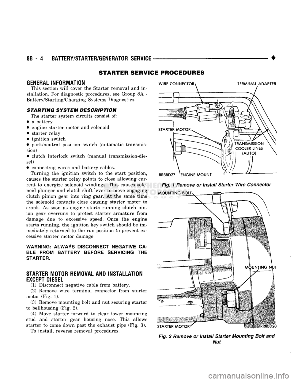
(2) Remove wire terminal connector from starter
motor (Fig. 1). (3) Remove mounting bolt and nut securing starter
to bellhousing (Fig. 2).
(.4) Move starter forward to clear lower mounting
stud and starter gear housing nose. This allows
starter to come down past the exhaust pipe (Fig. 3). To install, reverse removal procedures.
Fig.
2
Remove
or Install
Starter
Mounting
Bolt
and
Nut
Page 353 of 1502
8D
- 2
IGNITION
SYSTEMS
•
A/C
CLUTCH RELAY STARTER RELAY
DATA LINK CONTROL
CONNECTOR
MODULE J9314-164
Fig.
1
Auto
Shut Down
Relay
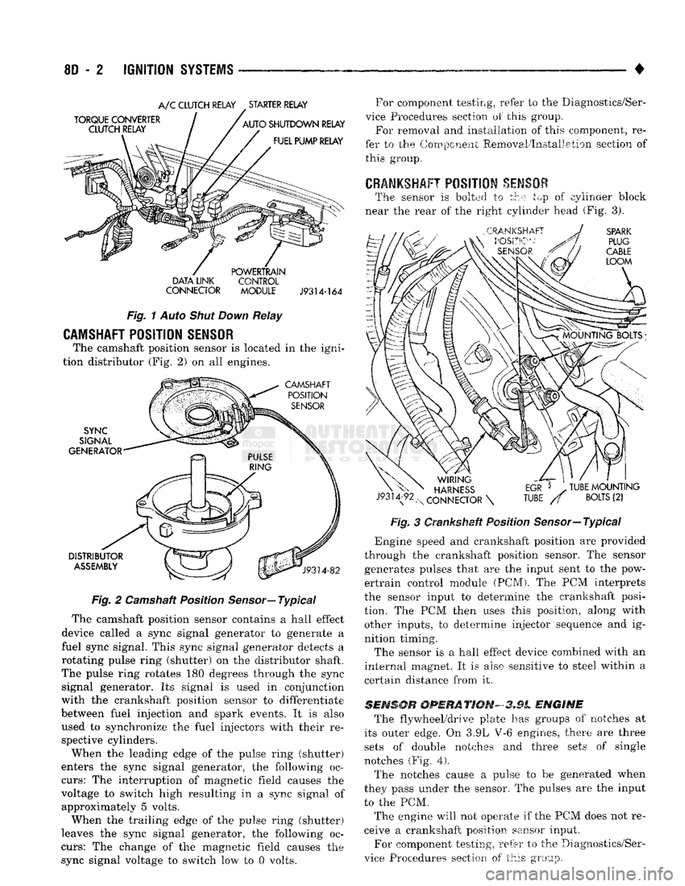
CAMSHAFT POSITION SENSOR
The camshaft position sensor is located in the igni
tion distributor (Fig. 2) on all engines.
Fig.
2 Camshaft Position
Sensor—
Typical
The camshaft position sensor contains a hall effect
device called a sync signal generator to generate a
fuel sync signal. This sync signal generator detects a
rotating pulse ring (shutter) on the distributor shaft.
The pulse ring rotates 180 degrees through the sync signal generator. Its signal is used in conjunction
with the crankshaft position sensor to differentiate
between fuel injection and spark events. It is also
used to synchronize the fuel injectors with their re spective cylinders.
When the leading edge of the pulse ring (shutter)
enters the sync signal generator, the following oc
curs:
The interruption of magnetic field causes the
voltage to switch high resulting in a sync signal of approximately 5 volts.
When the trailing edge of the pulse ring (shutter)
leaves the sync signal generator, the following oc
curs:
The change of the magnetic field causes the sync signal voltage to switch low to 0 volts. For component testing, refer to the Diagnostics/Ser
vice Procedures section of this group. For removal and installation of this component, re
fer to the Component Removal/Installation section of this group.
CRANKSHAFT
POSITION
SENSOR
The sensor is bolted to the top of cylinder block
near the rear of the right cylinder head (Fig. 3).
Fig.
3 Crankshaft Position Sensor—Typical
*
Engine speed and crankshaft position are provided
through the crankshaft position sensor. The sensor generates pulses that are the input sent to the pow
ertrain control module (PCM). The PCM interprets
the sensor input to determine the crankshaft posi
tion. The PCM then uses this position, along with other inputs, to determine injector sequence and ig
nition timing.
The sensor is a hall effect device combined with an
internal magnet. It is also sensitive to steel within a
certain distance from it.
SENSOR
OPERATION-3.9L
ENGINE
The flywheel/drive plate has groups of notches at
its outer edge. On 3.9L V-6 engines, there are three sets of double notches and three sets of single
notches (Fig.
4).
The notches cause a pulse to be generated when
they pass under the sensor. The pulses are the input to the PCM.
The engine will not operate if the PCM does not re
ceive a crankshaft position sensor input.
For component testing, refer to the Diagnostics/Ser
vice Procedures section of this group.
Page 356 of 1502
•
IGNITION
SYSTEMS
8D - 5
THROTTLE
^
BODY
u
BRACKET
y^SUPPORT
BRACKET
/ |
CHARGE
AIR
ijmmmmk
TEMPERATURE
SENSOR
THROTTLE
BODY
Fig.
9
Sensor
Location—3.9L Engine—Typical
INTAKE MANIFOLD
'b AIR TEMPERATURE
SENSOR
J9314-162
Fig.
10
Sensor
Location—5.2L/5.9L
Engines—Typical
start-up (cranking) and to engine load while the en
gine is running. The PCM uses this input, along with
inputs from other sensors, to adjust air-fuel mixture.
For more information, refer to Group 14, Fuel Sys
tem.
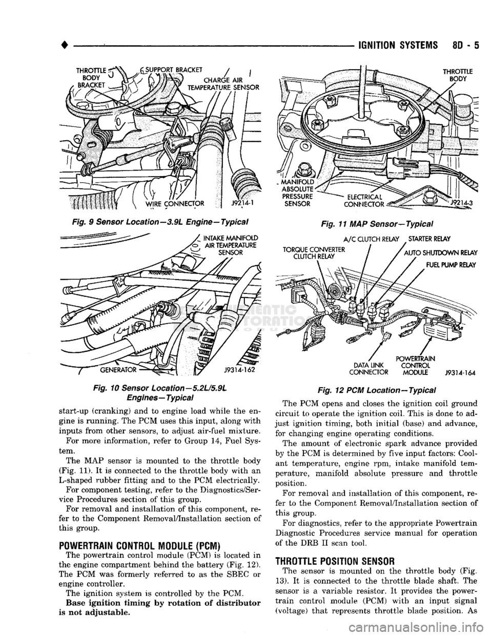
The MAP sensor is mounted to the throttle body
(Fig. 11). It is connected to the throttle body with an
L-shaped rubber fitting and to the PCM electrically. For component testing, refer to the Diagnostics/Ser
vice Procedures section of this group. For removal and installation of this component, re
fer to the Component Removal/Installation section of
this group.
POWERTRAIN CONTROL MODULE
(PCM) The powertrain control module (PCM) is located in
the engine compartment behind the battery (Fig. 12).
The PCM was formerly referred to as the SBEC or engine controller. The ignition system is controlled by the PCM. Base ignition timing by rotation of distributor
is not adjustable.
MANIFOLD
ABSOLUTE
PRESSURE
SENSOR
TORQUE CONVERTER CLUTCH RELAY
ELECTRICAL
Jlp^
CONNECTOR
^gis!—
Fig.
11 MAP Sensor—Typical
A/C
CLUTCH RELAY STARTER RELAY
AUTO
SHUTDOWN RELAY FUEL PUMP RELAY
DATA LINK
CONNECTOR POWERTRAIN
CONTROL
MODULE
J9314-164
Fig.
12 PCM Location—Typical The PCM opens and closes the ignition coil ground
circuit to operate the ignition coil. This is done to ad
just ignition timing, both initial (base) and advance, for changing engine operating conditions.
The amount of electronic spark advance provided
by the PCM is determined by five input factors: Cool ant temperature, engine rpm, intake manifold tem
perature, manifold absolute pressure and throttle
position.
For removal and installation of this component, re
fer to the Component Removal/Installation section of
this group.
For diagnostics, refer to the appropriate Powertrain
Diagnostic Procedures service manual for operation
of the DRB II scan tool.
THROTTLE
POSITION
SENSOR
The sensor is mounted on the throttle body (Fig.
13).
It is connected to the throttle blade shaft. The
sensor is a variable resistor. It provides the power-
train control module (PCM) with an input signal (voltage) that represents throttle blade position. As
Page 369 of 1502
8D
- 18
IGNITION
SYSTEMS
•
COMPONENT REMGWAL/INSTALLATION
INDEX
page
Automatic
Shut Down (ASD) Relay
18
Camshaft
Position
Sensor
, 18
Crankshaft Position
Sensor
18
Distributor
Service
20
Engine
Coolant Temperature
Sensor
20
General
Information
18
Ignition
Coil
21
page
Intake
Manifold Charge
Air
Temperature
Sensor
. 22
Manifold Absolute Pressure (MAP)
Sensor
..... 22
Oxygen
(02)
Sensor
22
Powertrain
Control
Module (PCM)
22
Spark
Plug Secondary Cables
24
Spark
Plugs
23
Throttle
Position
Sensor
(TPS)
24
GENERAL
INFORMATION
This section
of the
group, Component Removal/In
stallation, will discuss
the
removal
and
installation
of ignition system components. For basic ignition system diagnostics
and
service
adjustments, refer
to the
Diagnostics/Service Proce
dures section
of
this group. For system operation
and
component identification,
refer
to the
Component Identification/System Opera
tion section
of
this group.
AUTOMATIC
SHUT DOWN
(ASb)
RELAY
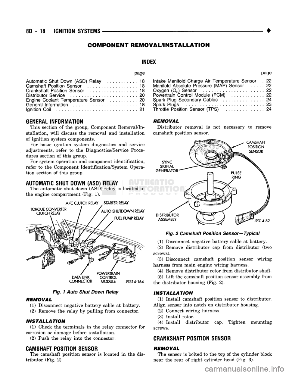
The automatic shut down
(ASD)
relay
is
located
in
the engine compartment
(Fig. 1).
TORQUE CONVERTER
CLUTCH RELAY
A/C
CLUTCH RELAY STARTER RELAY
AUTO
SHUTDOWN RELAY FUEL PUMP RELAY DATA UNK
CONNECTOR POWERTRAIN
CONTROL
MODULE
J9314-164
Fig.
1
Auto
Shut Down
Relay
REMOVAL
(1) Disconnect negative battery cable
at
battery.
(2)
Remove
the
relay
by
pulling from connector.
INSTALLATION
(1) Check
the
terminals
in the
relay connector
for
corrosion
or
damage before installation.
(2)
Push
the
relay into
the
connector.
CAMSHAFT POSITION SENSOR
The camshaft position sensor
is
located
in the
dis
tributor
(Fig. 2).
REMOVAL
Distributor removal
is not
necessary
to
remove
camshaft position sensor.
CAMSHAFT POSITION
SENSOR
SYNC
SIGNAL
GENERATOR
DISTRIBUTOR
ASSEMBLY
J9314-82
Fig.
2
Camshaft Position Sensor—Typical
(1) Disconnect negative battery cable
at
battery.
(2)
Remove distributor
cap
from distributor
(two
screws).
(3) Disconnect camshaft position sensor wiring
harness from main engine wiring harness.
(4) Remove distributor rotor from distributor shaft.
(5)
Lift
the
camshaft position sensor assembly from
the distributor housing
(Fig. 2).
INSTALLATION
(1) Install camshaft position sensor
to
distributor.
Align sensor into notch
on
distributor housing.
(2)
Connect wiring harness.
(3) Install rotor.
(4) Install distributor
cap.
Tighten mounting
screws.
CRANKSHAFT
POSITION SENSOR
REMOVAL The sensor
is
bolted
to the top of the
cylinder block
near
the
rear
of
right cylinder head
(Fig. 3).
Page 416 of 1502
•
VEHICLE SPEED CONTROL SYSTEM
8H - 1
VEHICLE SPEED CONTROL SYSTEM
CONTENTS
SERVICE
PROCEDURES
page
. 11
TEST PROCEDURES
page
.. 7
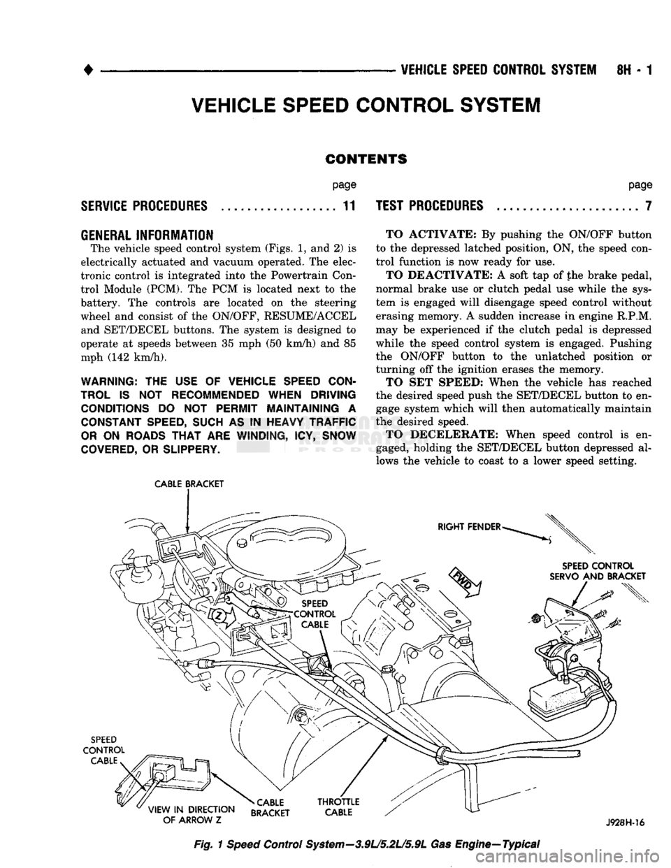
GENERAL
INFORMATION
The vehicle speed control system (Figs. 1, and 2) is
electrically actuated and vacuum operated. The elec
tronic control is integrated into the Powertrain Con trol Module (PCM). The PCM is located next to the
battery. The controls are located on the steering
wheel and consist of the ON/OFF, RESUME/ACCEL and SET/DECEL buttons. The system is designed to
operate at speeds between 35 mph (50 km/h) and 85
mph (142 km/h).
WARNING: THE USE OF VEHICLE SPEED CON
TROL IS NOT RECOMMENDED WHEN DRIVING CONDITIONS DO NOT PERMIT MAINTAINING A CONSTANT SPEED, SUCH AS IN HEAVY TRAFFIC
OR ON ROADS THAT ARE WINDING, ICY, SNOW
COVERED, OR SLIPPERY.
CABLE
BRACKET
TO ACTIVATE: By pushing the ON/OFF button
to the depressed latched position, ON, the speed con
trol function is now ready for use.
TO DEACTIVATE: A soft tap of the brake pedal,
normal brake use or clutch pedal use while the sys
tem is engaged will disengage speed control without
erasing memory. A sudden increase in engine R.P.M.
may be experienced if the clutch pedal is depressed
while the speed control system is engaged. Pushing
the ON/OFF button to the unlatched position or
turning off the ignition erases the memory.
TO SET SPEED: When the vehicle has reached
the desired speed push the SET/DECEL button to en gage system which will then automatically maintain
the desired speed. TO DECELERATE: When speed control is en
gaged, holding the SET/DECEL button depressed al
lows the vehicle to coast to a lower speed setting.
SPEED
CONTROL
SERVO
AND BRACKET
SPEED
CONTROL
CABLE
»CABLE
VIEW
IN
DIRECTION RRAfKFT
OF ARROW
Z BRACKET J928H-16
Fig.
1
Speed
Control System—3.9L/5.2L/5.9L Gas Engine—Typical
Page 417 of 1502
8H - 2
VEHICLE SPEED CONTROL SYSTEM
• TO RESUME: After disengaging the speed control
system by tapping the brake or clutch pedal, push
the RESUME/ACCEL button to return vehicle to the
previously set speed. TO ACCELERATE: While speed control is en
gaged, hold the RESUME/ACCEL button depressed and release at a new desired speed. This will allow
the vehicle to continuously accelerate and set at a
higher speed setting.
TAP-UP: When the speed control system is en
gaged, tapping the RESUME/ACCEL button will in
crease the speed setting by 2 mph (3 km/h). The system will respond to multiple tap-ups.
TO ACCELERATE for PASSING: Depress the
accelerator as you would normally. When the pedal
is released the vehicle will return to the speed set
ting in memory.
SERVO
CONNECTOR
J918H-20
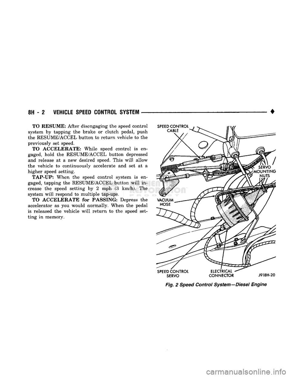
Fig.
2
Speed
Control
System
—Diesel
Engine
Page 493 of 1502
CLUTCH PEDAL POSITION
SWITCH TO RADIO
TO
MAP LP , TQ R,GHT
TO
MESSAGE
CENTER
\ \
DOOR WIRING
TO A/C-HTR
WRG
TO
HTR SW LP'
(2-WAY
CONN)1 TO PRINTED
CIRCUIT BOARD TO REAR
SPEAKERS
TO BODY WIRING
LIFTGATE AJAR
LAMP
VIEW
N
(CLUTCH
PEDAL POSITION SWITCH) CLUTCH
PEDAL
TO RADIO
TO CIGAR LIGHTER TO
CHASSIS
CONN (R.W.A.L.;
TO
LEFT
DOOR SWITCH
INSTRUMENT
PANEL
INTERMITTENT
WIPER CONTROL TO STOP LAMP
&
BRAKE
SW
(DIESEL)
TO TRANSMISSION
OVERDRIVE
SWITCH
TO
MESSAGE
CENTER 4WD
INDICATOR VIEW
IN
DIRECTION
OF ARROW
S
VIEW
P
(R.W.A.L. DATA LINK CONNECTOR) VIEW
IN
DIRECTION
OF ARROW
R 25
n
o
>
a
>
2
m
J938W-96
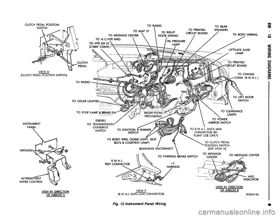
Fig.
12 instrument
Panel
Wiring
Page 496 of 1502
WINDSHIELD
WIPER MOTOR
TO RIGHT
HEADLAMP
PARK/TURN
SIGNAL LAMP TO FUSIBLE LINK
CIRCUITS
TO VEHICLE SPEED
CONTROL SEE VIEW
Z
EEMC
RELAY
LEFT
HEADLAMP
GROUND
ENGINE
STARTER
A/C RELAY
COMPRESSOR
CLUTCH RELAY AUTOMATIC SHUT
DOWN RELAY
FUEL PUMP RELAY
BULKHEAD
DISCONNECT
A/C
LOW
PRESSURE
SWITCH
SIDE
MARKER LAMP
TO UNDERHOOD LAMP WIRING
VEHICLE
SPEED
CONTROL
SERVO
POWERTRAIN
CONTROL MODULE
A/C
CYCLING SWITCH TO BLOWER
MTR &
WINDSHIELD
WASHER
MTR
VIEW
IN
DIRECTION OF ARROW
Z
VIEW
IN
DIRECTION
OF ARROW
W a
o
>
o 30
>
2
m
J938W-99
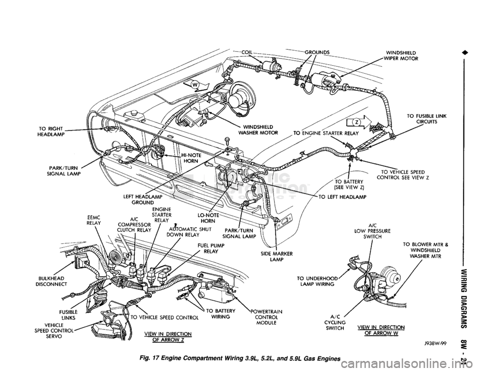
Fig.
17
Engine
Compartment Wiring 3.9L, 5.2L, and 5.9L Gas
Engines