1993 DODGE TRUCK cooling
[x] Cancel search: coolingPage 677 of 1502
9
- 72 5.2L
ENGINE
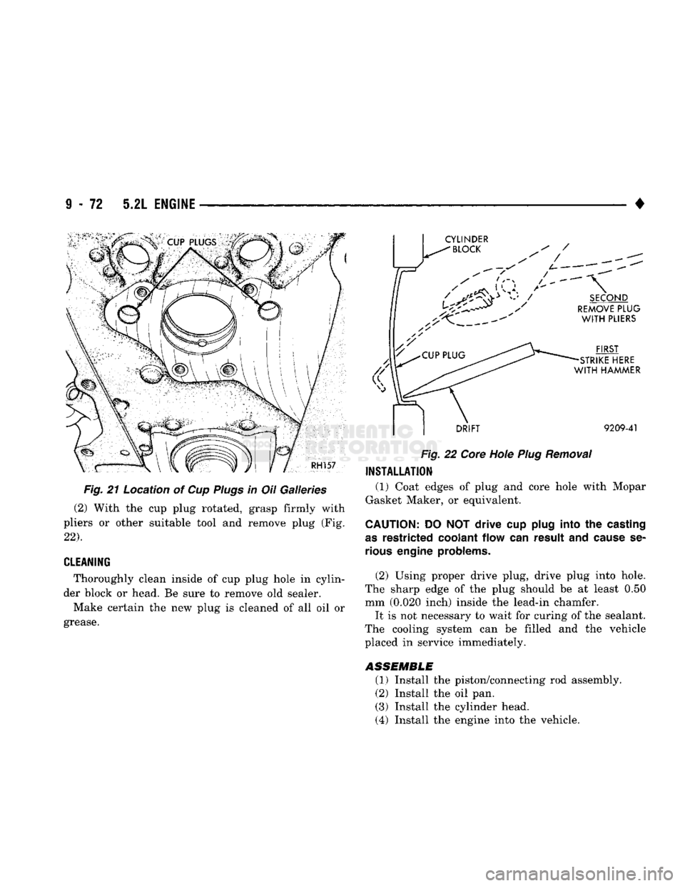
Fig. 21 Location of Cup Plugs in Oil Galleries
(2) With the cup plug rotated, grasp firmly with
pliers or other suitable tool and remove plug (Fig.
22).
CLEANING
Thoroughly clean inside of cup plug hole in cylin
der block or head. Be sure to remove old sealer.
Make certain the new plug is cleaned of all oil or
grease.
CYLINDER
"
BLOCK
' /
DRIFT
9209-41
Fig. 22 Core Hole Plug Removal
INSTALLATION
(1) Coat edges of plug and core hole with Mopar
Gasket Maker, or equivalent.
CAUTION:
DO NOT drive cup
plug
into the
casting
as
restricted coolant flow can result and
cause
se
rious
engine
problems.
(2) Using proper drive plug, drive plug into hole.
The sharp edge of the plug should be at least 0.50
mm (0.020 inch) inside the lead-in chamfer.
It is not necessary to wait for curing of the sealant.
The cooling system can be filled and the vehicle
placed in service immediately.
ASSEMBLE
(1) Install the piston/connecting rod assembly.
(2) Install the oil pan. (3) Install the cylinder head.
(4) Install the engine into the vehicle.
Page 682 of 1502
5.9L
ENGINE SERVICE PROCEDURES
INDEX
page
Camshaft
91
Crankshaft
98
Crankshaft Main Bearings
99
Crankshaft Rear
Oil
Seals
100
Cylinder
Block
101
Cylinder
Head Cover
81
Cylinder
Heads
82
Distributor
92
Engine Assembly
80
Engine
Front
Mounts
77
Engine Rear Mount
78
Front
Crankshaft
Oil
Seal Replacement
91
page
General
Information
77
Hydraulic
Tappets
87
Oil
Pan 93
Oil Pump
. 94
Piston
/
Connecting
Rod
Assembly
96
Rocker Arms
81
Specifications—5.9L
Engine
103
Timing
Chain Cover
89
Valve Stem Shield
/
Spring Replacement
86
Valve
Timing
. 88
Valves
/
Valve Springs
84
Vibration
Damper
88
GENERAL
INFORMATION
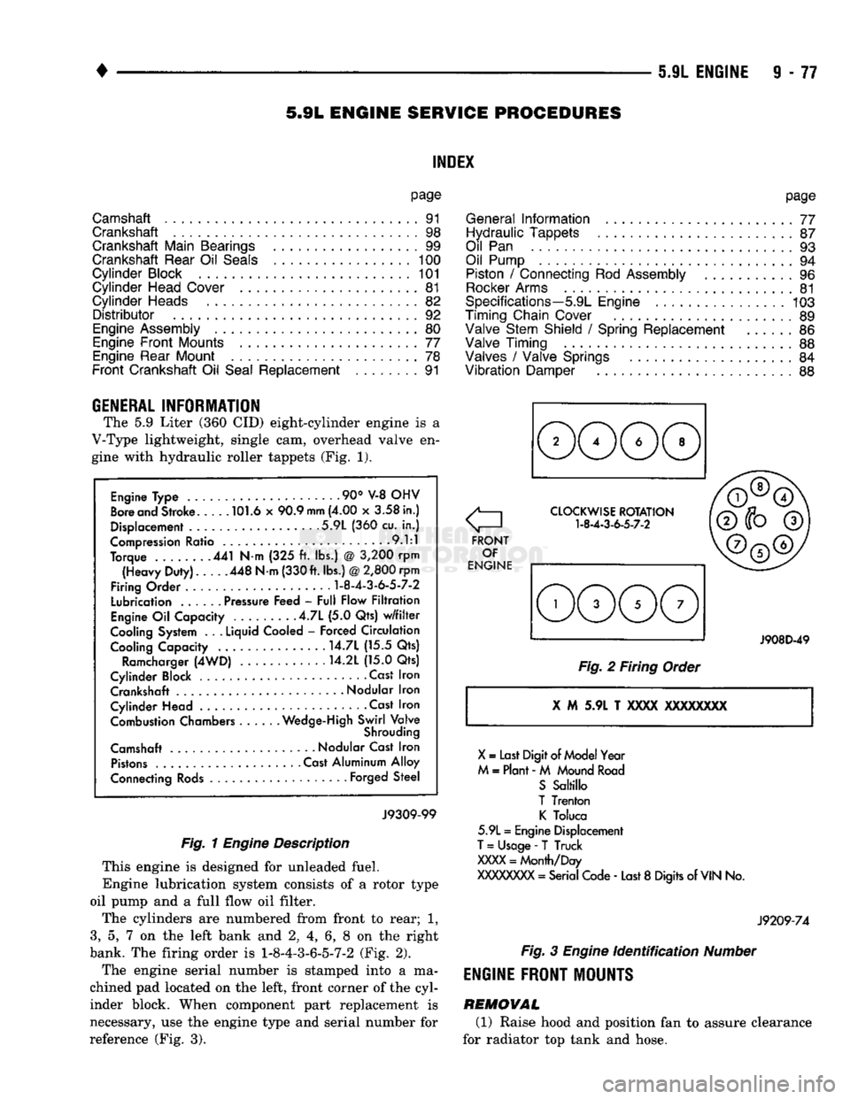
The 5.9 Liter (360 CID) eight-cylinder engine is a
V-Type lightweight, single cam, overhead valve en
gine with hydraulic roller tappets (Fig. 1).
Engine Type .90° V-8 OHV
Bore and Stroke 101.6 x 90.9
mm
(4.00 x 3.58 in.)
Displacement 5.9L (360 cu. in.)
Compression Ratio 9.1:1
Torque 441 N-m (325 ft. lbs.) @ 3,200 rpm (Heavy Duty). 448 N-m (330 ft. lbs.)
@
2,800 rpm
Firing Order
1-8-4-3-6-5-7-2
Lubrication ...... Pressure Feed - Full Flow Filtration
Engine Oil Capacity .4.7L (5.0 Qts) w/filter
Cooling System . .
.
Liquid Cooled - Forced Circulation Cooling Capacity ..... . . 14.7L (15.5 Qts)
Ramcharger (4WD) 14.2L (15.0 Qts)
Cylinder Block Cast Iron Crankshaft
-
Nodular Iron
Cylinder Head • . Cast Iron Combustion Chambers Wedge-High Swirl Valve
Shrouding
Camshaft Nodular Cast Iron Pistons Cast Aluminum Alloy
Connecting Rods Forged Steel
J9309-99
Fig. 1
Engine
Description
This engine is designed for unleaded fuel.
Engine lubrication system consists of a rotor type
oil pump and a full flow oil filter.
The cylinders are numbered from front to rear; 1,
3,
5, 7 on the left bank and 2, 4, 6, 8 on the right
bank. The firing order is
1-8-4-3-6-5-7-2
(Fig. 2).
The engine serial number is stamped into a ma
chined pad located on the left, front corner of the cyl
inder block. When component part replacement is
necessary, use the engine type and serial number for
reference (Fig. 3).
o
FRONT OF
ENGINE CLOCKWISE ROTATION
1-8-4-3-6-5-7-2
J908D-49
Fig. 2 Firing Order
X
M 5.9L T
XXXX
XXXXXXXX
X
= Last Digit of Model Year
M = Plant - M Mound Road S Saltillo
T Trenton K Toluca
5.9L = Engine Displacement
T
= Usage -
T
Truck
XXXX
= Month/Day
XXXXXXXX
= Serial Code - Last 8 Digits of
VIN
No.
J9209-74
Fig.
3
Engine
identification
Number
ENGINE
FRONT MOUNTS
REMOVAL (1) Raise hood and position fan to assure clearance
for radiator top tank and hose.
Page 685 of 1502
9
- 80 5.9L
ENGINE
•
TRANSFER
CASE
TRANSFER
CASE
ENGINE REAR
SUPPORT
PLATE
INSULATOR
MOUNTING
PLATE
LOWER
INSULATOR
\7"
RAIL
1
J9109-244
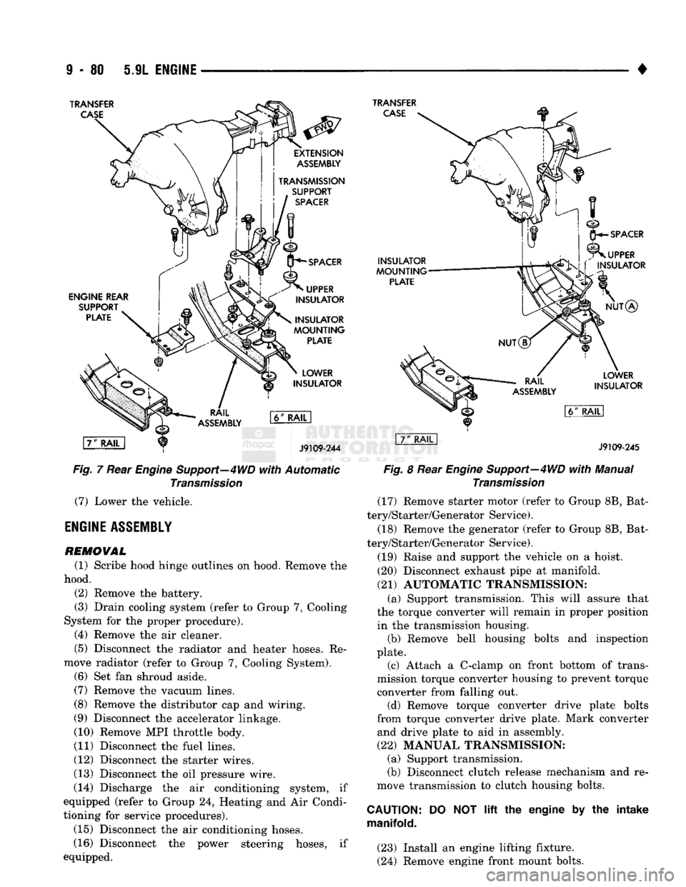
Fig.
7 Rear
Engine
Support—4WD
with
Automatic
Transmission
(7) Lower the vehicle.
ENGINE
ASSEMBLY
REMOVAL
(1) Scribe hood hinge outlines on hood. Remove the
hood. (2) Remove the battery.
(3) Drain cooling system (refer to Group 7, Cooling
System for the proper procedure). (4) Remove the air cleaner.
(5) Disconnect the radiator and heater hoses. Re
move radiator (refer to Group 7, Cooling System). (6) Set fan shroud aside.
(7) Remove the vacuum lines.
(8) Remove the distributor cap and wiring.
(9) Disconnect the accelerator linkage.
(10) Remove MPI throttle body.
(11) Disconnect the fuel lines.
(12) Disconnect the starter wires.
(13) Disconnect the oil pressure wire.
(14) Discharge the air conditioning system, if
equipped (refer to Group 24, Heating and Air Condi
tioning for service procedures).
(15) Disconnect the air conditioning hoses.
(16) Disconnect the power steering hoses, if
equipped.
INSULATOR
MOUNTING
PLATE
SPACER
UPPER
INSULATOR
NUT®
LOWER
INSULATOR
J9109-245
Fig.
8 Rear
Engine
Support—4WD
with
Manual
Transmission
(17) Remove starter motor (refer to Group 8B, Bat
tery/Starter/Generator Service).
(18) Remove the generator (refer to Group 8B, Bat
tery/Starter/Generator Service).
(19) Raise and support the vehicle on a hoist.
(20) Disconnect exhaust pipe at manifold.
(21) AUTOMATIC TRANSMISSION: (a) Support transmission. This will assure that
the torque converter will remain in proper position in the transmission housing. (b) Remove bell housing bolts and inspection
plate. (c) Attach a C-clamp on front bottom of trans
mission torque converter housing to prevent torque converter from falling out. (d) Remove torque converter drive plate bolts
from torque converter drive plate. Mark converter and drive plate to aid in assembly.
(22) MANUAL TRANSMISSION; (a) Support transmission.
(b) Disconnect clutch release mechanism and re
move transmission to clutch housing bolts.
CAUTION:
manifold.
DO
NOT
lift
the engine by the intake
(23) Install an engine lifting fixture.
(24) Remove engine front mount bolts.
Page 686 of 1502
•
5.9L ENGINE
9-81 (25) Lower the vehicle.
(26) On automatic transmission vehicles, discon
nect the engine from the torque converter drive
plate. On manual transmission vehicles, move engine forward until drive pinion shaft clears the clutch
disc.
Remove engine from engine compartment.
(27) Install engine assembly on engine repair
stand.
INSTALLATION (1) Remove engine from the repair stand and posi
tion in the engine compartment.
(2) Install an engine support fixture.
(3) Raise and support the vehicle on a hoist.
(4)
AUTOMATIC TRANSMISSION: (a) Position the torque converter and drive plate.
Install torque converter drive plate bolts. Tighten
the bolts to 31 Nnn (270 in. lbs.) torque.
(b) Install the engine front mounts.
(c) Install bell housing bolts. Tighten the bolts to
41 Nnn (30 ft. lbs.) torque.
(d) Remove C-clamp.
(e) Install the inspection plate.
(5)
MANUAL TRANSMISSION: (a) Position the drive pinion shaft to the clutch
disc.
(b) Connect the clutch release mechanism and
install the transmission to clutch bolts. Tighten the
bolts to 68 Nnn (50 ft. lbs.) torque.
(c) Install the engine front mounts.
(6) Remove transmission support.
(7) Install exhaust pipe to manifold. (8) Lower the vehicle.
(9) Remove engine lifting fixture.
(10) Install the generator (refer to Group 8B, Bat
tery/Starter/Generator Service). (11) Install the starter motor (refer to Group 8B,
Battery/Starter/Generator Service).
(12) Connect power steering hoses, if so equipped.
(13) Connect air conditioning hoses.
(14) Evacuate and charge the air conditioning sys
tem, if equipped (refer to Group 24, Heater and Air Conditioning for service procedures).
(15) Using a new gasket, install MPI throttle body.
Tighten the throttle body bolts to 23 Nnn (200 in. lbs.) torque.
(16) Connect the accelerator linkage. (17) Connect the starter wires.
(18) Connect the oil pressure wire.
(19) Install the distributor cap and wiring.
(20) Connect the vacuum lines.
(21) Connect the fuel lines.
(22) Install the radiator (refer to Group 7, Cooling
System). Connect the radiator hoses and heater
hoses.
(23) Install fan shroud in position.
(24) Fill cooling system (refer to Group 7, Cooling
System for the proper procedure). (25) Install the air cleaner.
(26) Install the battery.
(27) Warm engine and adjust.
(28) Install hood and line up with the scribe
marks. (29) Road test vehicle.
CYLINDER HEAD COVER
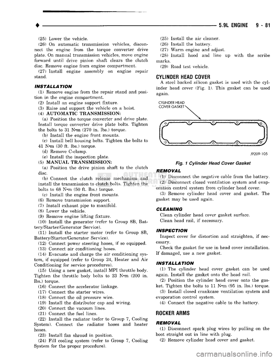
A steel backed silicon gasket is used with the cyl
inder head cover (Fig. 1). This gasket can be used
again.
CYLINDER HEAD
J9209-105
Fig.
1 Cylinder Head
Cover
Gasket
REMOVAL (1) Disconnect the negative cable from the battery.
(2) Disconnect closed ventilation system and evap
oration control system from cylinder head cover.
(3) Remove cylinder head cover and gasket. The
gasket may be used again.
CLEANING
Clean cylinder head cover gasket surface.
Clean head rail, if necessary.
INSPECTION Inspect cover for distortion and straighten, if nec
essary.
Check the gasket for use in head cover installation.
If damaged, use a new gasket.
INSTALLATION (1) The cylinder head cover gasket can be used
again. Install the gasket onto the head rail.
(2) Position the cylinder head cover onto the gas
ket. Tighten the bolts to 11 Nnn (95 in. lbs.) torque. (3) Install closed crankcase ventilation system and
evaporation control system.
(4) Connect the negative cable to the battery.
ROCKER
ARMS
REMOVAL (1) Disconnect spark plug wires by pulling on the
boot straight out in line with plug.
(2) Remove cylinder head cover and gasket.
Page 687 of 1502
9
- 82 5.9L
ENGINE
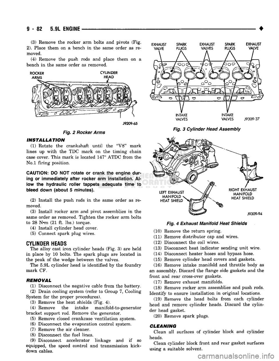
• (3) Remove the rocker arm bolts and pivots (Fig.
2).
Place them on a bench in the same order as re
moved. (4) Remove the push rods and place them on a
bench in the same order as removed.
ROCKER
CYLINDER
J9209-65
Fig.
2
Rocker Arms INSTALLATION
(1) Rotate the crankshaft until the "V8" mark
lines up with the TDC mark on the timing chain
case cover. This mark is located 147° ATDC from the
No.l firing position.
CAUTION:
DO NOT
rotate
or crank the engine dur
ing
or
immediately
after
rocker
arm installation. Al
low the hydraulic roller tappets adequate
time
to
bleed
down
(about 5 minutes).
(2) Install the push rods in the same order as re
moved.
(3) Install rocker arm and pivot assemblies in the
same order as removed. Tighten the rocker arm bolts
to 28 N*m (21 ft. lbs.) torque. (4) Install cylinder head cover.
(5) Connect spark plug wires.
CYLINDER HEADS The alloy cast iron cylinder heads (Fig. 3) are held
in place by 10 bolts. The spark plugs are located in
the peak of the wedge between the valves. The 5.9L cylinder head is identified by the foundry
mark CF.
REMOVAL
(1) Disconnect the negative cable from the battery.
(2) Drain cooling system (refer to Group 7, Cooling
System for the proper procedures).
(3) Remove the heat shields (Fig. 4).
(4) Remove the intake manifold-to-generator
bracket support rod. Remove the generator.
(5) Remove closed crankcase ventilation system. (6) Disconnect the evaporation control system.
(7) Remove the air cleaner.
(8) Disconnect the fuel lines.
(9) Disconnect accelerator linkage and if so
equipped, the speed control and transmission kick- down cables.
EXHAUST SPARK EXHAUST SPARK EXHAUST
VALVE PLUGS VALVES PLUGS VALVE
INTAKE INTAKE
VALVES
VALVES
J9309-37
Fig.
3 Cylinder Head
Assembly
Fig.
4
Exhaust
Manifold Heat
Shields
(10) Remove the return spring.
(11) Remove distributor cap and wires.
(12) Disconnect the coil wires.
(13) Disconnect heat indicator sending unit wire.
(14) Disconnect heater hoses and bypass hose.
(15) Remove cylinder head covers and gaskets.
(16) Remove intake manifold and throttle body as
an assembly. Discard the flange side gaskets and the
front and rear cross-over gaskets.
(17) Remove exhaust manifolds.
(18) Remove rocker arm assemblies and push rods.
Identify to ensure installation in original locations. (19) Remove the head bolts from each cylinder
head and remove cylinder heads. Discard the cylin der head gasket.
(20) Remove spark plugs.
CLEANING
Clean all surfaces of cylinder block and cylinder
heads.
Clean cylinder block front and rear gasket surfaces
using a suitable solvent.
Page 689 of 1502
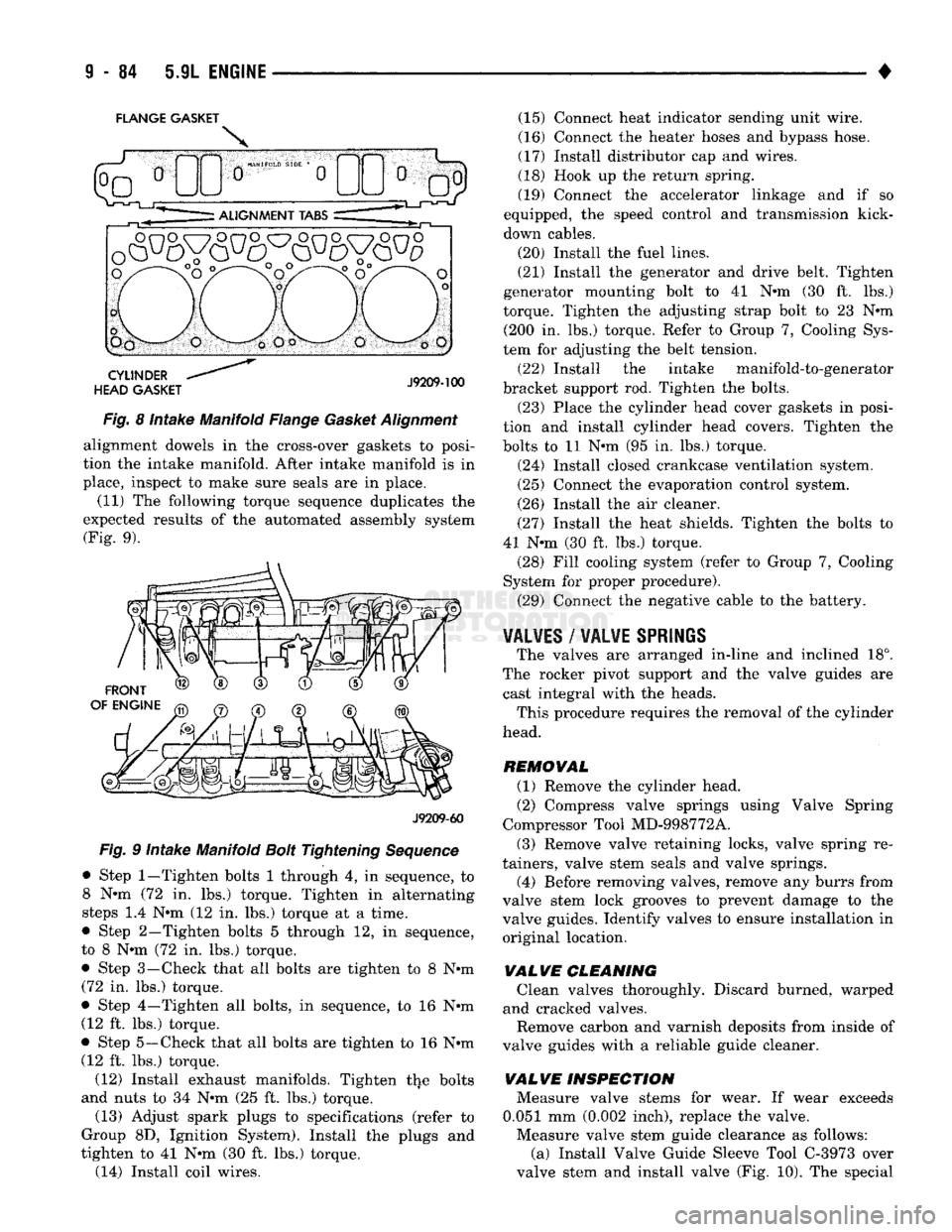
FLANGE GASKET
Fig. 8 Intake Manifold Flange Gasket Alignment alignment dowels in the cross-over gaskets to posi
tion the intake manifold. After intake manifold is in
place, inspect to make sure seals are in place.
(11) The following torque sequence duplicates the
expected results of the automated assembly system (Fig. 9).
J9209-60
Fig. 9 Intake Manifold Bolt Tightening Sequence
• Step
1—Tighten
bolts 1 through 4, in sequence, to 8 N-m (72 in. lbs.) torque. Tighten in alternating
steps 1.4 N-m (12 in. lbs.) torque at a time.
• Step 2—Tighten bolts 5 through 12, in sequence,
to 8 N-m (72 in. lbs.) torque. • Step 3—-Check that all bolts are tighten to 8 N-m
(72 in. lbs.) torque.
• Step 4—Tighten all bolts, in sequence, to 16 N-m (12 ft. lbs.) torque.
• Step 5—Check that all bolts are tighten to 16 N-m (12 ft. lbs.) torque.
(12) Install exhaust manifolds. Tighten the bolts
and nuts to 34 N-m (25 ft. lbs.) torque.
(13) Adjust spark plugs to specifications (refer to
Group 8D, Ignition System). Install the plugs and
tighten to 41 N-m (30 ft. lbs.) torque. (14) Install coil wires. (15) Connect heat indicator sending unit wire.
(16) Connect the heater hoses and bypass hose.
(17) Install distributor cap and wires.
(18) Hook up the return spring.
(19) Connect the accelerator linkage and if so
equipped, the speed control and transmission kick-
down cables.
(20) Install the fuel lines.
(21) Install the generator and drive belt. Tighten
generator mounting bolt to 41 N-m (30 ft. lbs.)
torque. Tighten the adjusting strap bolt to 23 N-m (200 In. lbs.) torque. Refer to Group 7, Cooling Sys
tem for adjusting the belt tension.
(22) Install the intake manifold-to-generator
bracket support rod. Tighten the bolts.
(23) Place the cylinder head cover gaskets in posi
tion and install cylinder head covers. Tighten the
bolts to 11 N-m (95 in. lbs.) torque.
(24) Install closed crankcase ventilation system.
(25) Connect the evaporation control system.
(26) Install the air cleaner.
(27) Install the heat shields. Tighten the bolts to
41 N-m (30 ft. lbs.) torque. (28) Fill cooling system (refer to Group 7, Cooling
System for proper procedure).
(29) Connect the negative cable to the battery.
¥AL¥ES
/
WALWE SPRIliS
The valves are arranged in-line and inclined 18°.
The rocker pivot support and the valve guides are cast integral with the heads. This procedure requires the removal of the cylinder
head.
REMOVAL (1) Remove the cylinder head.
(2) Compress valve springs using Valve Spring
Compressor Tool MD-998772A.
(3) Remove valve retaining locks, valve spring re
tainers, valve stem seals and valve springs.
(4) Before removing valves, remove any burrs from
valve stem lock grooves to prevent damage to the
valve guides. Identify valves to ensure Installation in original location,
VALVE
CLEANING Clean valves thoroughly. Discard burned, warped
and cracked valves.
Remove carbon and varnish deposits from Inside of
valve guides with a reliable guide cleaner.
VALVE
INSPECTION Measure valve stems for wear. If wear exceeds
0.051 mm (0.002 Inch), replace the valve.
Measure valve stem guide clearance as follows: (a) Install Valve Guide Sleeve Tool C-3973 over
valve stem and install valve (Fig. 10). The special
Page 693 of 1502
9
- 88 5.9L
ENGINE
•
CAUTION:
The
plunger
and
tappet
bodies
are not
interchangeable,.
The
plunger
and
valve must
al
ways
be
fitted
to the
original
body,
It is
advisable
to
work
on one
tappet
at a time to
avoid mixing
of
parts. Mixed parts
are not
compatible.
DO
NOT dis
assemble
a
tappet
on a dirty
work bench.
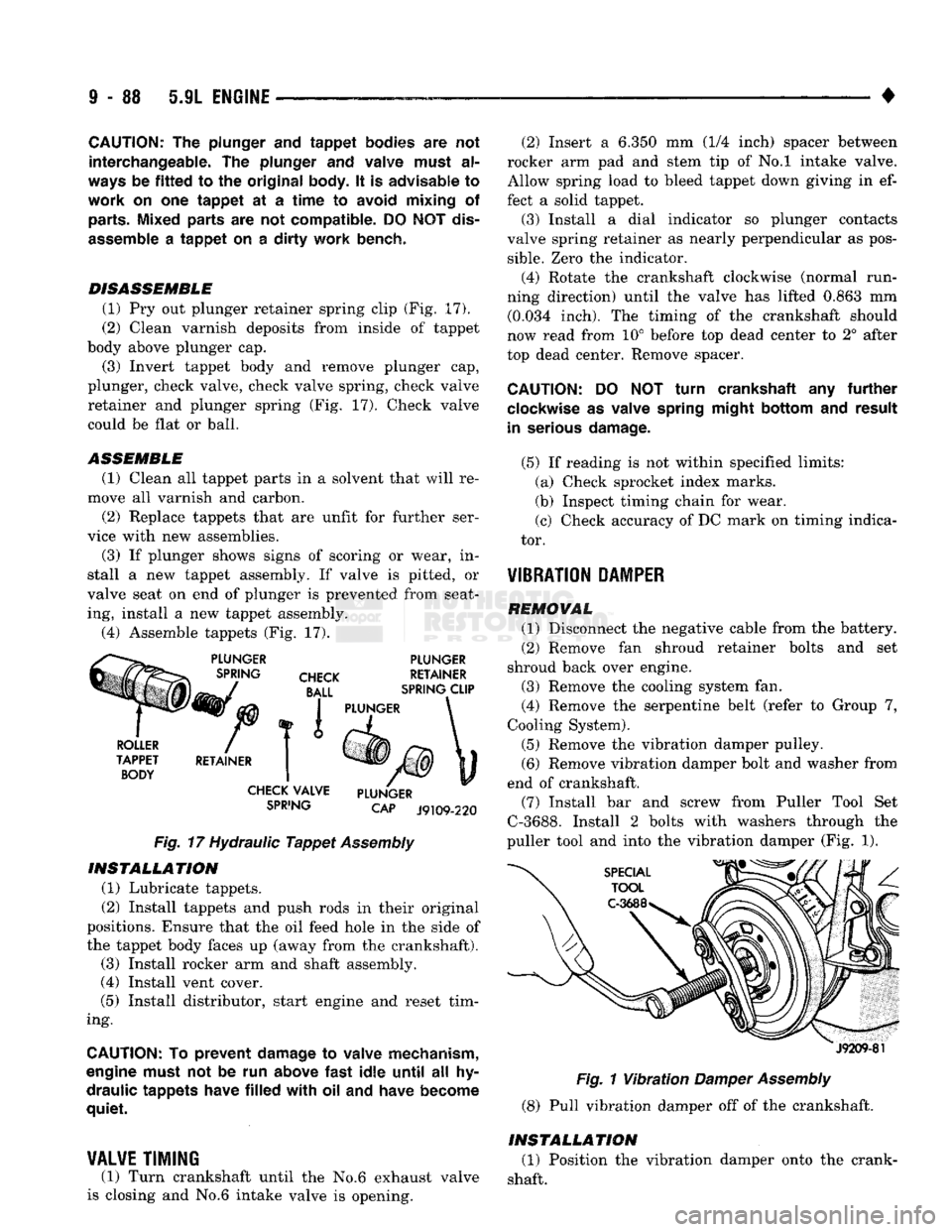
DISASSEMBLE (1) Pry out plunger retainer spring clip (Fig. 17).
(2) Clean varnish deposits from inside of tappet
body above plunger cap.
(3) Invert tappet body and remove plunger cap,
plunger, check valve, check valve spring, check valve
retainer and plunger spring (Fig, 17). Check valve
could be flat or ball.
ASSEMBLE
(1) Clean all tappet parts in a solvent that will re
move all varnish and carbon. (2) Replace tappets that are unfit for further ser
vice with new assemblies.
(3) If plunger shows signs of scoring or wear, in
stall a new tappet assembly. If valve is pitted, or
valve seat on end of plunger is prevented from seat ing, install a new tappet assembly.
(4) Assemble tappets (Fig. 17).
SPiING
CAP J9109-220
Fig.
17 Hydraulic
Tappet
Assembly INSTALLATION
(1) Lubricate tappets.
(2) Install tappets and push rods in their original
positions. Ensure that the oil feed hole In the side of
the tappet body faces up (away from the crankshaft). (3) Install rocker arm and shaft assembly.
(4) Install vent cover.
(5) Install distributor, start engine and reset tim
ing.
CAUTION:
To
prevent damage
to
valve mechanism,
engine must
not be run
above
fast
idle
until
all hy
draulic tappets have
filled
with oil and
have become
quiet.
¥AL¥E
TIMING
(1) Turn crankshaft until the No.6 exhaust valve
is closing and No.6 intake valve Is opening. (2) Insert a 6.350 mm (1/4 inch) spacer between
rocker arm pad and stem tip of No.l intake valve.
Allow spring load to bleed tappet down giving in ef
fect a solid tappet. (3) Install a dial indicator so plunger contacts
valve spring retainer as nearly perpendicular as pos
sible.
Zero the Indicator.
(4) Rotate the crankshaft clockwise (normal run
ning direction) until the valve has lifted 0.863 mm (0.034 inch). The timing of the crankshaft should
now read from 10° before top dead center to 2° after
top dead center. Remove spacer.
CAUTION:
DO NOT
turn crankshaft
any
further
clockwise
as
valve spring might bottom
and
result
in serious damage.
(5) If reading is not within specified limits: (a) Check sprocket index marks.
(b) Inspect timing chain for wear.
(c) Check accuracy of DC mark on timing indica
tor. -
¥IBRATI0N
PAMPER
REMOVAL (1) Disconnect the negative cable from the battery.
(2) Remove fan shroud retainer bolts and set
shroud back over engine. (3) Remove the cooling system fan.
(4) Remove the serpentine belt (refer to Group 7,
Cooling System). (5) Remove the vibration damper pulley. (6) Remove vibration damper bolt and washer from
end of crankshaft. (7) Install bar and screw from Puller Tool Set
C-3688. Install 2 bolts with washers through the
puller tool and into the vibration damper (Fig. 1).
J9209-81
Fig.
1
Vibration
Damper
Assembly
(8) Pull vibration damper off of the crankshaft.
INSTALLATION (1) Position the vibration damper onto the crank
shaft.
Page 694 of 1502
•
5.9L
ENGINE
9 - 89
(2) Place installing tool, part of Puller Tool Set
C-3688 in position and press the vibration damper
onto the crankshaft (Fig. 2).
Fig. 2 Installing Vibration Damper (3) Install the crankshaft bolt and washer. Tighten
the bolt to 183 N-m (135 ft. lbs.) torque.
(4) Install the crankshaft pulley. Tighten the pul
ley bolts to 23 N-m (200 In. lbs.) torque.
(5) Install the serpentine belt (refer to Group 7,
Cooling System). (6) Install the cooling system fan. Tighten the
bolts to 23 N-m (17 ft. lbs.) torque.
(7) Position the fan shroud and install the bolts.
Tighten the retainer bolts to 11 N-m (95 in. lbs.)
torque.
(8) Connect the negative cable to the battery.
TIMING CHAIN COWER
REMOVAL
(1) Disconnect the negative cable from the battery.
(2) Drain cooling system (refer to Group 7, Cooling
System).
(3) Remove the serpentine belt (refer to Group 7,
Cooling System). (4) Remove water pump (refer to Group 7, Cooling
System).
(5) Remove power steering pump (refer to Group
19,
Steering). (6) Remove vibration damper.
(7) Remove fuel lines (refer to Group 14, Fuel Sys
tem).
(8) Loosen oil pan bolts and remove the front bolt
at each side. (9) Remove the cover bolts.
(10) Remove chain case cover and gasket using ex
treme caution to avoid damaging oil pan gasket.
(11) Place a suitable tool behind the lips of the oil
seal to pry the oil seal outward. Be careful not to
damage the crankshaft seal surface of cover (Fig. 3).
TIMING
CHAIN
STRETCH
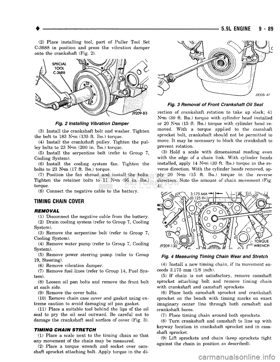
(1) Place a scale next to the timing chain so that
any movement of the chain may be measured.
(2) Place a torque wrench and socket over cam
shaft sprocket attaching bolt. Apply torque in the di- Fig. 3 Removal of Front Crankshaft Oil Seal
rection of crankshaft rotation to take up slack; 41
N-m (30 ft, lbs.) torque with cylinder head installed
or 20 N-m (15 ft. lbs.) torque with cylinder head re
moved. With a torque applied to the camshaft sprocket bolt, crankshaft should not be permitted to
move. It may be necessary to block the crankshaft to
prevent rotation.
(3) Hold a scale with dimensional reading even
with the edge of a chain link. With cylinder heads installed, apply 14 N-m (30 ft. lbs.) torque In the re
verse direction. With the cylinder heads removed, ap
ply 20 N-m (15 ft. lbs.) torque In the reverse direction. Note the amount of chain movement (Fig.
4).
Fig. 4 Measuring Timing Chain Wear and Stretch
(4) Install a new timing chain, if its movement ex
ceeds 3.175 mm (1/8 inch). (5) If chain is not satisfactory, remove camshaft
sprocket attaching bolt and remove timing chain
with crankshaft and camshaft sprockets,
(6) Place both camshaft sprocket and crankshaft
sprocket on the bench with timing marks on exact
imaginary center line through both camshaft and
crankshaft bores.
(7) Place timing chain around both sprockets.
(8) Turn crankshaft and camshaft to line up with
keyway location in crankshaft sprocket and in cam
shaft sprocket.
(9) Lift sprockets and chain (keep sprockets tight
against the chain in position as described).