1993 DODGE TRUCK cooling
[x] Cancel search: coolingPage 884 of 1502
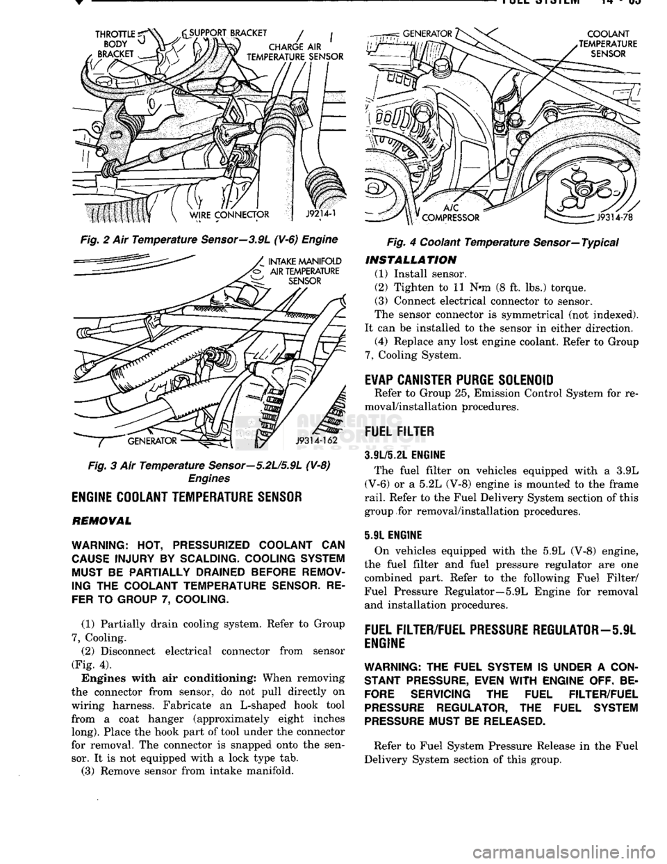
Fig. 2 Ait Temperature Sensor—3.9L (¥-6) Engine
Fig. 3 Air Temperature Sensor—5.2U5.9L (V-8)
Engines
ENGINE
COOLANT
TEMPERATURE
SENSOR
REMOVAL
WARNING:
HOT,
PRESSURIZED COOLANT
CAN
CAUSE
INJURY
BY
SCALDING- COOLING SYSTEM MUST
BE
PARTIALLY DRAINED BEFORE REMOV
ING
THE
COOLANT TEMPERATURE
SENSOR.
RE
FER
TO
GROUP
7,
COOLING.
(1) Partially drain cooling system. Refer to Group
7,
Cooling. (2) Disconnect electrical connector from sensor
(Fig. 4).
Engines with air conditioning: When removing
the connector from sensor, do not pull directly on
wiring harness. Fabricate an L-shaped hook tool from a coat hanger (approximately eight inches
long).
Place the hook part of tool under the connector
for removal. The connector is snapped onto the sen sor. It is not equipped with a lock type tab.
(3) Remove sensor from intake manifold. Fig. 4 Coolant Temperature Sensor—Typical
INSTALLATION
(1) Install sensor.
(2) Tighten to 11 Nnn (8 ft. lbs.) torque.
(3) Connect electrical connector to sensor.
The sensor connector is symmetrical (not indexed).
It can be installed to the sensor in either direction. (4) Replace any lost engine coolant. Refer to Group
7,
Cooling System.
E¥AP
CANISTER
PURGE
SOLENOID
Refer to Group 25, Emission Control System for re
moval/installation procedures.
FUEL
FILTER
3.9L/5.21.
ENGINE
The fuel filter on vehicles equipped with a 3.9L
(V-6) or a 5.2L (V-8) engine is mounted to the frame
rail.
Refer to the Fuel Delivery System section of this
group for removal/installation procedures.
5.91 ENGINE
On vehicles equipped with the 5.9L (V-8) engine,
the fuel filter and fuel pressure regulator are one combined part. Refer to the following Fuel Filter/
Fuel Pressure Regulator—5.9L Engine for removal and installation procedures.
FUEL
FILTER/FUEL
PRESSURE
REGULATOR—5JL
ENGINE
WARNING:
THE FUEL SYSTEM IS UNDER A
CON
STANT
PRESSURE,
EVEN
WITH
ENGINE OFF. BE
FORE
SERVICING THE FUEL FILTER/FUEL
PRESSURE
REGULATOR, THE FUEL SYSTEM
PRESSURE
MUST BE
RELEASED.
Refer to Fuel System Pressure Release in the Fuel
Delivery System section of this group.
Page 898 of 1502
•
FUEL SYSTEM
14-79
OVERDRIVE/OVERRIDE SWITCH-PCM
INPUT
The overdrive/override switch is not used with
manual transmissions. On vehicles equipped with overdrive, the PCM reg
ulates the 3-4 overdrive upshift and downshift
through the overdrive solenoid. An override switch is located on the instrument panel. The overdrive/override switch is a momentary con
tact switch. The switch contacts are normally open. When the switch is activated, the PCM will receive a ground signal. The transmission will not enter over
drive when the operator presses the override switch.
The transmission downshifts if the operator presses
the override switch while in overdrive.
COOLANT TEMPERATURE SENSOR The coolant temperature sensor is not used with
manual transmissions.
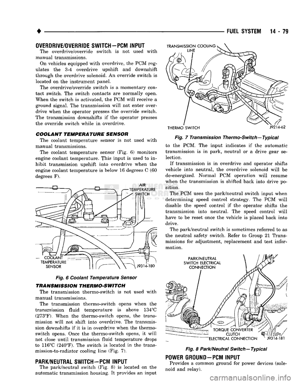
The coolant temperature sensor (Fig. 6) monitors
engine coolant temperature. This input is used to in
hibit transmission upshift into overdrive when the
engine coolant temperature is below 16 degrees C (60
degrees F).
Fig.
6 Coolant
Temperature
Sensor
TRANSMISSION THERMO-SWITCH The transmission thermo-switch is not used with
manual transmissions.
The transmission thermo-switch opens when the
transmission fluid temperature is above 134°C (273°F). When the thermo-switch opens, the trans
mission will not shift into overdrive. The transmis sion downshifts if it is in overdrive when the thermo-
switch opens. Once the thermo-switch opens, it will
not close until transmission fluid temperature drops
to 116°C (240°F). The switch is located in the trans mission-to-radiator cooling line (Fig. 7).
PARK/NEUTRAL SWITCH-PCM
INPUT
The park/neutral switch (Fig. 8) is located on the
automatic transmission housing. It provides an input
THERMO SWITCH
J9214-62
Fig.
7
Transmission
Thermo-Switch—Typical to the PCM. The input indicates if the automatic
transmission is in park, neutral or a drive gear se lection.
If transmission is in overdrive and operator shifts
vehicle into neutral, the overdrive solenoid will be de-energized. Normal PCM operation will resume
when the transmission is shifted back into drive po sition.
The PCM uses the park/neutral switch input when
determining speed control strategy. The PCM will
disable the speed control if the operator shifts the
transmission into neutral. The speed control will
have to be reset once the vehicle is placed back into drive.
The park/neutral switch is sometimes referred to as
the neutral safety switch. Refer to Group 21 Trans missions for adjustment, replacement and test infor
mation.
Fig.
8 Park/Neutral Switch—Typical
POWER
GROUND-PCM
INPUT
Provides a common ground for power devices (sole
noid and relay).
Page 975 of 1502
19
- 14
STEERING
• (9) Install the fluid hoses to the power steering
pump, Tighten the pressure fitting at the pump to 30
N*m (22 ft. lbs.) torque.
(10) Install and clamp the hose on the vacuum
pump. (11) Fill the reservoir with power steering fluid
only. If necessary, refer to Pump Initial Operation
for detailed instructions.
(12) Start and run the engine. Check the operation
of the brakes, if necessary refer to Group 5, Brakes
for additional information.
PUMP REPLACEMENT—GASOLINE ENGINE
REMOVAL
WARNING:
DO NOT
REMOVE
THE
WATER PUMP COOLANT TUBE UNLESS
THE
COOLANT SYSTEM HAS BEEN DEPRESSUR1ZED
AND
DRAINED*
WARNING:
DO NOT
ATTEMPT
TO
REMOVE
THE
PUMP
WITHOUT
REMOVING
THE
BELT FIRST.
THE
AUTOMATIC TENSIONER
IS
UNDER
A
HIGH
SPRING
LOAD.
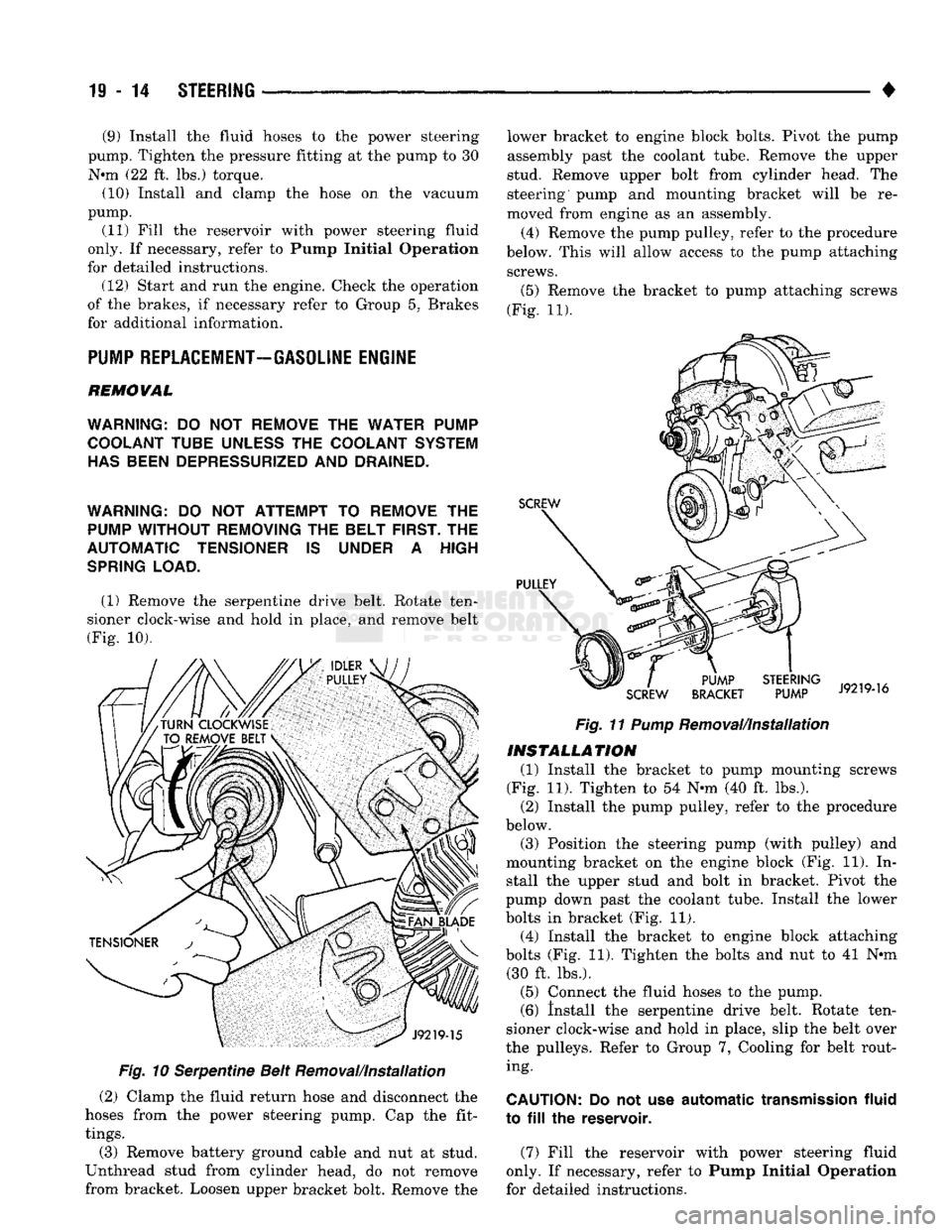
(1) Remove the serpentine drive belt. Rotate ten
sioner clock-wise and hold in place, and remove belt
(Fig. 10).
Fig.
10 Serpentine Belt Removal/Installation
(2) Clamp the fluid return hose and disconnect the
hoses from the power steering pump. Cap the fit
tings.
(3) Remove battery ground cable and nut at stud.
Unthread stud from cylinder head, do not remove
from bracket. Loosen upper bracket bolt. Remove the lower bracket to engine block bolts. Pivot the pump
assembly past the coolant tube. Remove the upper
stud. Remove upper bolt from cylinder head. The
steering pump and mounting bracket will be re
moved from engine as an assembly.
(4) Remove the pump pulley, refer to the procedure
below. This will allow access to the pump attaching screws.
(5)
Remove the bracket to pump attaching screws
(Fig. 11).
Fig.
11
Pump
Removal/Installation
INSTALLATION
(1) Install the bracket to pump mounting screws
(Fig. 11). Tighten to 54 N-m (40 ft. lbs.). (2) Install the pump pulley, refer to the procedure
below.
(3) Position the steering pump (with pulley) and
mounting bracket on the engine block (Fig. 11). In stall the upper stud and bolt in bracket. Pivot the
pump down past the coolant tube. Install the lower
bolts in bracket (Fig. 11). (4) Install the bracket to engine block attaching
bolts (Fig. 11). Tighten the bolts and nut to 41 N*m (30 ft. lbs.).
(5) Connect the fluid hoses to the pump. (6) Install the serpentine drive belt. Rotate ten
sioner clock-wise and hold in place, slip the belt over
the pulleys. Refer to Group 7, Cooling for belt rout ing.
CAUTION:
Do not use
automatic
transmission
fluid
to
fill the
reservoir.
(7) Fill the reservoir with power steering fluid
only. If necessary, refer to Pump Initial Operation
for detailed instructions.
Page 1078 of 1502
•
AUTOMATIC
TRANSMISSION—32RH/3SRH/37RH/42RH/48RH
21 - 77
Flow
Control And Lubrication
The manual valve is operated by the gearshift link
age and provides the operating range selected by the
driver.
The 1-2 shift valve provides automatic 1-2 or 2-1
shifts and the 2-3 shift valve provides automatic 2-3
or 3-2 shifts.
The kickdown valve provides forced 3-2 or 3-1
downshifts depending on vehicle speed. Downshifts
occur when the throttle is opened beyond downshift
detent position which is just before wide open throt
tle.
The 2-3 valve throttle pressure plug provides 3-2
downshifts with varying throttle openings and de
pending on vehicle speed.
The 1-2 shift control valve transmits 1-2 shift pres
sure to the accumulator piston to control kickdown
band capacity on 1-2 upshifts and 3-2 downshifts.
The limit valve determines maximum speed at
which a 3-2 part throttle kickdown can be made. Some transmissions do not have the limit valve and
maximum speed for a 3-2 kickdown is at the detent
position.
The shuttle valve has two functions. First is fast
front band release and smooth engagement during "lift foot" 2-3 upshifts. Second is to regulate front
clutch release and band application during 3-2 down
shifts.
The converter clutch valve applies the converter
modulated clutch when supplied with line pressure through the converter clutch solenoid. The solenoid is
controlled by and connected to the powertrain control module through a connector in the transmission case.
Electronic control of converter clutch engagement
includes disengagement at closed throttle during
warmup and during part throttle acceleration. Non- converter clutch transmissions have a threaded plug at the rear of the transmission case in place of the
solenoid wiring connector.
The fail safe valve restricts feed to the converter
clutch if front clutch pressure drops. It permits clutch
engagement only in direct (third) gear and provides
fast clutch release during kickdown.
The switch valve directs apply fluid pressure to the
converter clutch in one position and releases it in the
opposite position. It also directs oil to the cooling and
lube circuits. The switch valve regulates oil pressure
to the torque converter by limiting maximum oil
pressure to 130 psi.
Clutch/Band
Application The front/rear clutch pistons and servo pistons are
actuated by line pressure. When line pressure is re
moved, the pistons are released by spring tension.
On 2-3 upshifts, the front servo piston is released
by spring tension and hydraulic pressure. The accu mulator controls hydraulic pressure on the apply side
of the front servo during 1-2 upshifts and at all
throttle openings.
Page 1085 of 1502
21 - 84
AUTOMATIC TRANSMISSION-32RH/36RH/37RH/42RH/46RH
• The 3-4 timing valve is moved by line pressure
coming through the 3-4 shift valve. The timing valve
holds the 2-3 shift valve in an upshift position. The
purpose is to prevent the 2-3 valve from up or down shifting before the 3-4 valve. The 3-4 accumulator is mounted on the overdrive
housing. It performs the same function as the 2-3 ac cumulator. It is used to smooth engagement during
the 3-4 shift.
On models with a converter clutch, the clutch valve
applies the converter clutch when supplied with line
pressure through the converter clutch solenoid. The converter clutch solenoid is mounted on the
valve body. It is energized by an electrical signal
from the powertrain control module. Electronic con
trol of converter clutch engagement includes disen gagement at closed throttle during warmup and
during part throttle acceleration.
The switch valve directs apply fluid pressure to the
converter clutch in one position and releases it in the
opposite position. It also directs oil to the cooling and
lube circuits. The switch valve regulates oil pressure
to the torque converter by limiting maximum oil
pressure to 130 psi.
Boost
Valve Function The boost valve provides increased fluid apply pres
sure for converter clutch and overdrive clutch en
gagement.
The boost valve is connected to the overdrive clutch
circuit via a tube connected between the valve body
upper and lower housings. The valve is connected to
the converter clutch circuit via the regulator valve, switch valve and 3-4 shift and timing valves.
Hydraulic circuitry for the boost valve is shown in
the hydraulic flow diagrams. The diagrams are lo cated at the end of the transmission diagnosis and
test section.
During converter clutch engagement in fourth
gear, the valve supplies full line pressure directly to
the clutch. The increased pressure available at the clutch provides smooth shifting and positive engage
ment. The 3-4 upshift causes the boost valve to increase
line pressure to the overdrive clutch. Pressure also
increases with throttle opening. This ensures positive
clutch engagement during periods of high throttle
opening acceleration.
Converter
Clutch
Control The converter clutch valve applies the converter
clutch when supplied with line pressure through the
converter clutch solenoid. The solenoid is mounted on
the valve body and energized by an electrical signal
from the powertrain control module. Electronic con
trol of converter clutch operation includes clutch re lease at closed throttle during warmup and during
part throttle acceleration. The boost valve provides additional apply pressure for converter clutch appli
cation.
The switch valve directs fluid apply pressure to the
converter clutch in one position and releases it in the
opposite position. It also directs oil to the cooling and lube circuits. The switch valve regulates oil pressure
to the torque converter by limiting maximum oil
pressure to 130 psi.
Clutch/Band
Application The clutch and servo pistons are actuated by line
pressure. When fluid pressure is released, the pistons are released by spring pressure.
On 2-3 upshifts, the front servo piston is released
by spring tension and hydraulic pressure. The accu mulator controls hydraulic pressure on the apply side of the front servo during 1-2 upshifts and all throttle
openings.
The overdrive direct clutch is applied by spring
pressure. The direct clutch is applied in all ranges except fourth gear.
The overdrive clutch is applied in fourth gear only.
The clutch is applied by the overdrive piston which is actuated by line pressure through the 3-4 shift valve.
Page 1105 of 1502
21 - 104
AUTOMATIC
TRANSMISSION—32RH/36RH/37RH/42RH/46RH
•
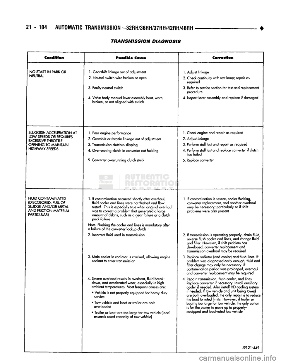
Condition
POMIOSO
Ccwse
Correction
NO
START
IN
PARK
OR
NEUTRAL
1.
Gearshift
linkage
out
of
adjustment
2.
Neutral
switch
wire
broken
or
open
3.
Faulty
neutral
switch
4.
Valve
body
manual
lever
assembly
bent,
worn,
broken,
or not
aligned
with
switch
1.
Adjust linkage
2.
Check continuity
with
test lamp; repair as required
3.
Refer to service section for test and replacement procedure
4.
inspect lever
assembly
and replace if damaged
SLUGGISH
ACCELERATION
AT
LOW
SPEEDS
OR
REQUIRES
EXCESSIVE
THROTTLE
OPENING
TO MAINTAIN
HIGHWAY
SPEEDS
1.
Poor
engine
performance
2.
Gearshift
or
throttle
linkage
out of adjustment
3.
Transmission
clutches slipping
4.
Overrunning clutch in converter not holding
5. Converter overrunning clutch stuck
1.
Check engine and repair as required
2. Adjust linkage
3. Perform stall test and repair as required
4.
Perform stall test and replace converter if clutch
has
failed
5. Replace converter
FLUID
CONTAMINATED
(DISCOLORED,
FULL
OF
SLUDGE
AND/OR
METAL
AND
FRICTION
MATERIAL
PARTICULAR)
1.
If contamination occurred shortly
after
overhaul,
fluid cooler and
lines
were
not
flushed
and flow rested. This is especially
true
when original overhaul
was
to correct a problem
that
generated a large
amount of debris,
such
as a gear
failure
or a clutch
pack
failure
Note: Flushing the cooler and lines is mandatory
after
a
failure
of the converter lockup clutch
2.
Incorrect fluid used in transmission
3. Main cooler in radiator is cracked, allowing engine coolant to
enter
transmission
4.
Severe overload results in overheat, fluid break
down,
and accelerated wear, especially in high
ambient temperatures.
Most
frequent
causes
are:
• Vehicle is not properly equipped for heavy duty
service
• Tow vehicle and boat or
trailer
are both overloaded
•
Trailer
or boat are too large for tow vehicle (load exceeds rated capacity of tow vehicle)
1.
If contamination is severe, cooler flushing,
converter replacement, and another overhaul may be
necessary;
particularly so if shift
problems
were
also
present
2.
If
transmission
is operating properly, drain fluid, reverse flush cooler and lines, and change fluid
and
filter.
However, if shift problem has
developed, converter replacement and
transmission
overhaul may be required
3.
Replace radiator (and cooler) and flush lines. If problem was
diagnosed
early
enough,
fluid and
filter
change
may
only
be
necessary.
If
contamination perioa was prolonged, overhaul
and
converter replacement may be required
4.
Repair
transmission,
flush cooler, and lines.
Replace
converter if
necessary.
Install auxiliary
cooler if needed.
Also
install HD cooling system if needed. If tow vehicle and unit being towed
are both overloaded, the only repair is to reduce
the load to
rated
limits. However, if
trailer
or boat is too large for tow vehicle, the only option
is
for the owner to move up to properly-
equipped and load-rated tow vehicle
J9121-449
TRANSMISSION DIAGNOSIS
Page 1386 of 1502
•
BODY
COMPONENTS
23 - 3
GRILLE
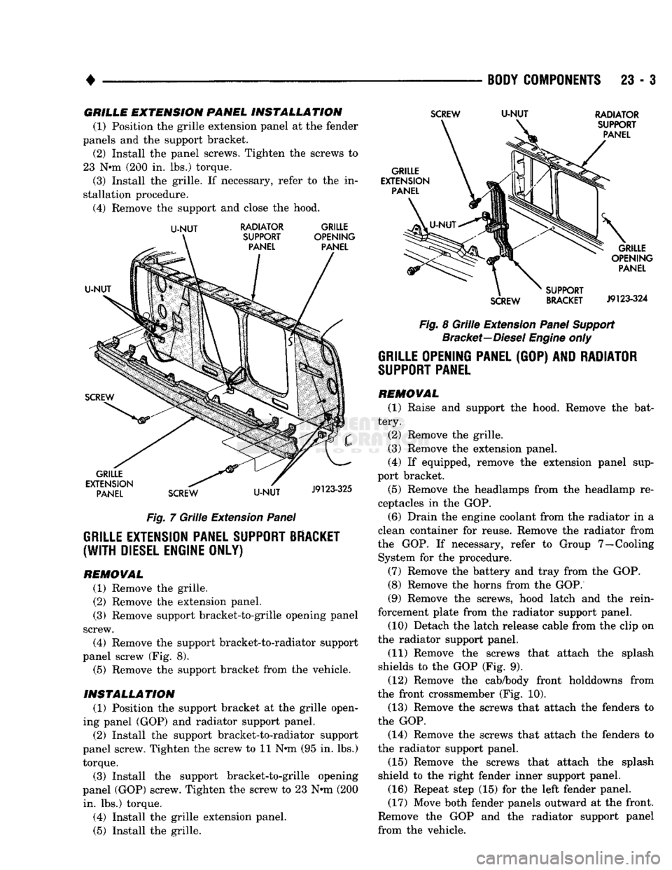
EXTENSION
PANEL
INSTALLATION
(1) Position the grille extension panel at the fender
panels and the support bracket. (2) Install the panel screws. Tighten the screws to
23 N*m (200 in. lbs.) torque.
(3) Install the grille. If necessary, refer to the in
stallation procedure. (4) Remove the support and close the hood.
U-NUT
RADIATOR GRILLE
Fig. 7 Grille Extension Panel
GRILLE EXTENSION PANEL SUPPORT BRACKET
(WITH
DIESEL ENGINE ONLY)
REMOWAL
(1) Remove the grille.
(2) Remove the extension panel.
(3) Remove support bracket-to-grille opening panel
screw. (4) Remove the support bracket-to-radiator support
panel screw (Fig. 8). (5) Remove the support bracket from the vehicle.
INSTALLATION
(1) Position the support bracket at the grille open
ing panel (GOP) and radiator support panel. (2) Install the support bracket-to-radiator support
panel screw. Tighten the screw to 11 N*m (95 in. lbs.) torque.
(3) Install the support bracket-to-grille opening
panel (GOP) screw. Tighten the screw to 23 N-m (200 in. lbs.) torque.
(4) Install the grille extension panel.
(5) Install the grille.
SCREW
U-NUT
RADIATOR
Fig. 8 Grille Extension Panel Support Bracket—Diesel Engine only
GRILLE OPENING PANEL
(GOP) AND
RADIATOR
SUPPORT
PANEL
REMOVAL
(1) Raise and support the hood. Remove the bat
tery. (2) Remove the grille.
(3) Remove the extension panel.
(4) If equipped, remove the extension panel sup
port bracket.
(5) Remove the headlamps from the headlamp re
ceptacles in the GOP.
(6) Drain the engine coolant from the radiator in a
clean container for reuse. Remove the radiator from
the GOP. If necessary, refer to Group 7—Cooling System for the procedure.
(7) Remove the battery and tray from the GOP.
(8) Remove the horns from the GOP.
(9) Remove the screws, hood latch and the rein
forcement plate from the radiator support panel. (10) Detach the latch release cable from the clip on
the radiator support panel.
(11) Remove the screws that attach the splash
shields to the GOP (Fig. 9). (12) Remove the cab/body front holddowns from
the front crossmember (Fig. 10). (13) Remove the screws that attach the fenders to
the GOP.
(14) Remove the screws that attach the fenders to
the radiator support panel.
(15) Remove the screws that attach the splash
shield to the right fender inner support panel.
(16) Repeat step (15) for the left fender panel.
(17) Move both fender panels outward at the front.
Remove the GOP and the radiator support panel
from the vehicle.
Page 1387 of 1502
23
- 4
BODY
COMPONENTS
• INSTALLATION
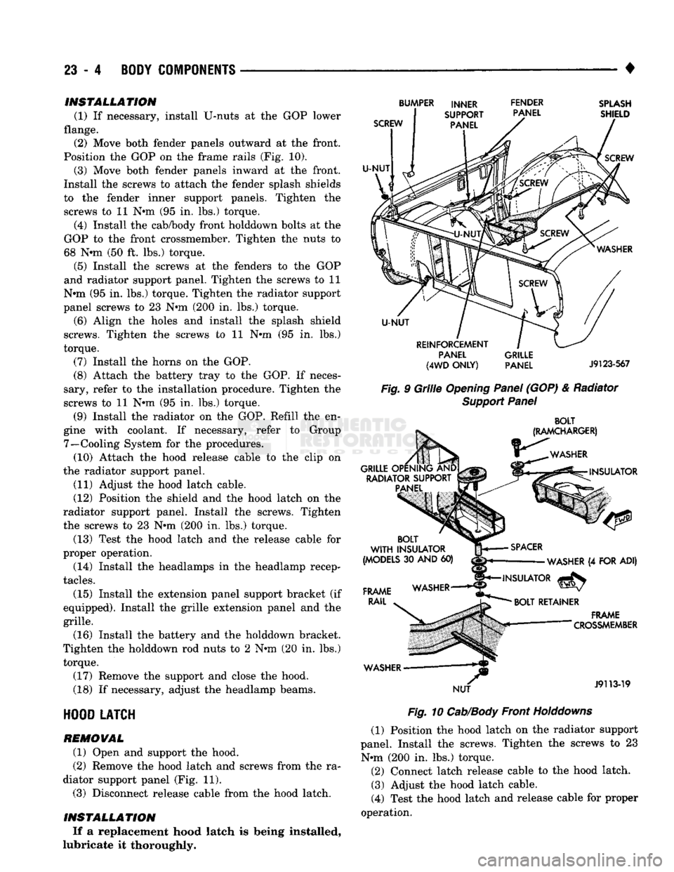
(1) If necessary, install U-nuts at the GOP lower
flange. (2) Move both fender panels outward at the front.
Position the GOP on the frame rails (Fig. 10).
(3) Move both fender panels inward at the front.
Install the screws to attach the fender splash shields
to the fender inner support panels. Tighten the
screws to 11 N#m (95 in. lbs.) torque.
(4) Install the cab/body front holddown bolts at the
GOP to the front crossmember. Tighten the nuts to
68 Nnn (50 ft. lbs.) torque.
(5) Install the screws at the fenders to the GOP
and radiator support panel. Tighten the screws to 11
N»m (95 in. lbs.) torque. Tighten the radiator support
panel screws to 23 Nnn (200 in. lbs.) torque.
(6) Align the holes and install the splash shield
screws. Tighten the screws to 11 N»m (95 in. lbs.)
torque.
(7) Install the horns on the GOP.
(8) Attach the battery tray to the GOP. If neces
sary, refer to the installation procedure. Tighten the
screws to 11 Nnn (95 in. lbs.) torque.
(9) Install the radiator on the GOP. Refill the en
gine with coolant. If necessary, refer to Group 7—Cooling System for the procedures. (10) Attach the hood release cable to the clip on
the radiator support panel.
(11) Adjust the hood latch cable.
(12) Position the shield and the hood latch on the
radiator support panel. Install the screws. Tighten
the screws to 23 Nnn (200 in. lbs.) torque.
(13) Test the hood latch and the release cable for
proper operation.
(14) Install the headlamps in the headlamp recep
tacles.
(15) Install the extension panel support bracket (if
equipped). Install the grille extension panel and the
grille.
(16) Install the battery and the holddown bracket.
Tighten the holddown rod nuts to 2 Nnn (20 in. lbs.) torque.
(17) Remove the support and close the hood.
(18) If necessary, adjust the headlamp beams.
HOOD
LATCH
REMOVAL
(1) Open and support the hood.
(2) Remove the hood latch and screws from the ra
diator support panel (Fig. 11). (3) Disconnect release cable from the hood latch.
INSTALLATION If a replacement hood latch is being installed,
lubricate it thoroughly.
SCREW
U-NUT
BUMPER INNER FENDER
SUPPORT PANEL
PANEL
SPLASH
SHIELD
SCREW
U-NUT
REINFORCEMENT PANEL
(4WD
ONLY)
GRILLE
PANEL
J9123-567
Fig.
9
Grille
Opening
Panel
(GOP) & Radiator
Support
Panel
BOLT
(RAMCHARGER)
WASHER
GRILLE OPENING AND RADIATOR SUPPORT PANEL INSULATOR
BOLT
WITH
INSULATOR
(MODELS
30
AND
60)
FRAME
RAIL
WASHER NUT
SPACER
WASHER
(4
FOR ADI)
INSULATOR
^
BOLT
RETAINER
.
FRAME
— "
"
CROSSMEMBER
J9113-19
Fig.
10
Cab/Body
Front
Holddowns
(1) Position the hood latch on the radiator support
panel. Install the screws. Tighten the screws to 23 Nnn (200 in. lbs.) torque. (2) Connect latch release cable to the hood latch. (3) Adjust the hood latch cable.
(4) Test the hood latch and release cable for proper
operation.