1993 DODGE TRUCK cooling
[x] Cancel search: coolingPage 1438 of 1502
•
• —• •
HEATING
AND AIR
CONDITIONING
24 - 1 CONTENTS
page
CLIMATE CONTROL SYSTEM
............. 21
REFRIGERANT SYSTEM SERWICE
COMPRESSOR
SERWICE
(SD-709)
......... 21
PROCEDURES
.............
DIAGNOSTIC PROCEDURES
3
TORQUE SPECIFICATIONS
GENERAL INFORMATION
1
page
. 17
. 31
GENERAL INFORMATION
HEATER SYSTEM
All models use a Blend-Air type heater. Outside air
enters the heater through the cowl opening and
passes through a plenum chamber to the heater core. Air intake openings must be kept free of snow, ice and other obstructions for the heater system to pick
up sufficient outside air. A temperature control door
in the heater housing directs incoming air through
the heater core and/or the heater core bypass. The amount of blend (heated and non-heated air) is deter
mined by the setting of the temperature lever on the
instrument panel. Direction of the blended air is con
trolled by the HEAT-DEFROST lever on the instru ment panel. The blower switch and resistor block controls the
speed of the blower motor. This in turn controls the
velocity of the air flow from the heater outlets. The resistor block consists of 2 helical wound wire
resistors connected to terminals which are mechani cally attached to a glass-filled phenolic board. This
assembly is bolted to the plenum. The blower switch controls the blower motor speed
by selectively connecting the resistors in series to the
blower motor.
A self-adjusting clip, on each of 2 control cables has
been incorporated to simplify cable adjustment. This clip snaps onto the control cable core wire and will slide along the wire under a specific load to provide
an automatic cable adjustment.
AIR
CONDITIONING
SYSTEM
Air intake openings must be kept free of snow, ice
and other obstructions for the air conditioning sys
tem to pick up sufficient outside air.
COMPONENTS
• COMPRESSOR-The seven piston SD-709 com
pressor is used on all vehicles. This compressor com
presses the low pressure refrigerant vapor into a high pressure, high temperature vapor. • CLUTCH PULLEY AND COIL-These are
mounted on the compressor, providing a convenient
way to drive it and disengage it in accordance to the cooling needs.
• CONDENSER-The condenser is located in front
of the radiator. Its function is to cool the hot, high
pressure refrigerant gas causing it to condense into
high pressure liquid refrigerant.
• FILTER-DRIER—The filter-drier is used to remove
any traces of moisture from the refrigerant system.
This component incorporates the sight glass and the
high pressure relief valve.
• SIGHT GLASS-The sight glass is provided as a
diagnostic tool to observe refrigerant flow and indi cate refrigerant level. It is located at the top of the
filter drier.
• HIGH -PRESSURE RELIEF VALVE-This is a safety device designed to open automatically if the
system pressure reaches a predetermined level. This
will prevent system component damage. • EXPANSION (H) VALVE-The expansion (H)
valve is used to meter refrigerant into the evaporator
in accordance with cooling requirements. • EVAPORATOR COIL-The evaporator coil is lo
cated in the A/C unit. Its function is to cool and de-
humidify the air before it enters the vehicle. • FREEZE CONTROL-The main function of freeze
control is to prevent water on the evaporator coil face
from freezing which restricts the airflow. An elec
tronic temperature cycling switch is located on the
refrigerant plumbing (suction line) near the H-Valve.
The switch turns the compressor ON-OFF depending
on the temperature in the suction line. The switch is a sealed, specially calibrated unit. If found defective,
the switch must be replaced. • REFRIGERANT LINES-These lines are needed
to carry the refrigerant between the various system components.
• CONDENSATE DRAIN TUBE-Condensation
which accumulates on the bottom of the evaporator
HEATING
AND AIR
CONDITIONING
Page 1440 of 1502
•
HEATING
AND AIR
CONDITIONING
24 - 3
DIAGNOSTIC
PROCEDURES
INDEX
page
page ..
7
General Information
3
.
. 3
Heating System Output
3
Air
Conditioning System
Blower
Motor
GENERAL
INFORMATION
The reason for owner dissatisfaction must be thor
oughly understood before any attempt is made to re
pair or replace any parts. It must be determined if
the condition is the heater system, the refrigerant system, air conditioning air flow or related to the
compressor. After confirming the condition, a func
tional test is suggested using the diagnostic charts.
After the condition has been properly diagnosed and corrected, check out the complete system to assure
that it is performing satisfactorily. The following charts have been developed for quick
reference. If the step by step method used is not com pletely understood, refer to the correct section of the Service Manual for detailed explanations.
HEATING
SYSTEM
OUTPUT
WARNING:
IF
VEHICLE
HAS
BEEN
RUN
RECENTLY,
WAIT
15
MINUTES
BEFORE
REMOVING
CAP, THEN
PLACE
A RAG
OVER
THE CAP AND
TURN
IT TO
THE
FIRST
STOP.
ALLOW
PRESSURE
TO
ESCAPE
THROUGH
THE
OVERFLOW
TUBE
AND
WHEN
THE
SYSTEM
STABILIZES,
REMOVE
THE CAP
COM
PLETELY.
Check the radiator coolant level, drive belt tension,
engine vacuum line connections, radiator air flow and radiator fan operation. Start engine and bring to
normal operating temperature (refer to Group 7,
Cooling System).
Engine coolant is provided to the heater system by
2 heater hoses. With engine idling at normal operat
ing temperature, set the heater control to maximum
heat, defrost and high blower setting. Using a test
thermometer, check the air temperature coming from
the defroster outlets (refer to Temperature Reference Chart).
Should the temperature not meet the minimum
values shown, refer to Heater Diagnosis (Mechanical)
for possible causes and corrections.
(1) Remove radiator pressure cap.
(2) Drain 1 pint of coolant from the radiator.
(3) Warm the engine to operating temperature by
idling for 20 minutes, with the pressure cap off. Idle longer if working outdoors in cold temperatures. (4) With the engine idling, place a thermometer
into the coolant in the radiator filler neck.
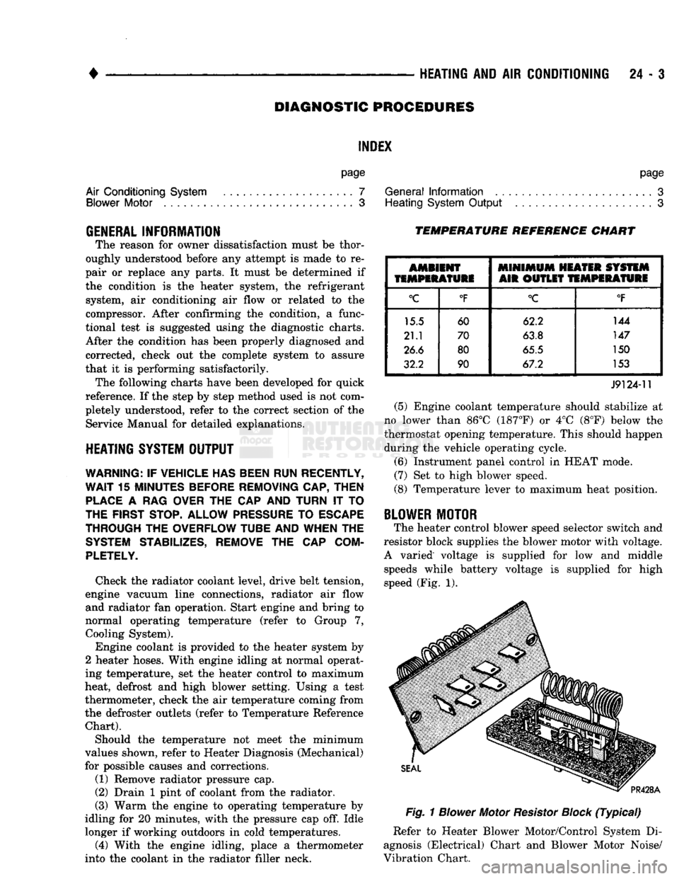
TEMPERATURE REFERENCE CHART
AMBIENT
MINIMUM
HEATER SYSTEM
TEMPERATURE
AIR OUTLET
TEMPERATURE
°C
°F
°C
°F
15.5 60 62.2 144
21.1 70
63.8 147
26.6 80
65.5 150
32.2 90 67.2 153
J9124-11
(5) Engine coolant temperature should stabilize at
no lower than 86°C (187°F) or 4°C (8°F) below the
thermostat opening temperature. This should happen during the vehicle operating cycle.
(6) Instrument panel control in HEAT mode.
(7) Set to high blower speed.
(8) Temperature lever to maximum heat position.
BLOWER
MOTOR
The heater control blower speed selector switch and
resistor block supplies the blower motor with voltage.
A varied voltage is supplied for low and middle speeds while battery voltage is supplied for high
speed (Fig. 1).
Fig.
1
Blower
Motor
Resistor
Block
(Typical)
Refer to Heater Blower Motor/Control System Di
agnosis (Electrical) Chart and Blower Motor Noise/
Vibration Chart.
Page 1441 of 1502
24
- 4
HEATING
AND
AIR
CONDITIONING
•
(1) Possible location or cause of blower motor vi
bration are as follows:
(a) Blower motor assembly loose in heater A/C
housing.
(b) Blower wheel loose on motor shaft.
(c) Blower wheel out of balance or bent.
(d) Blower motor defective.
(2) Possible location or cause of blower motor noise
are as follows: (To verify blower noise disconnect blower motor wire lead connector and operate heater
or A/C system. If noise goes away, proceed with pro
cedure.)
(a) Refer to vibration section of this procedure.
(b) Foreign material in Heater-A/C housing
around blower wheel.
(c) Blower wheel rubbing Heater-A/C housing.
(d) Blower motor defective.
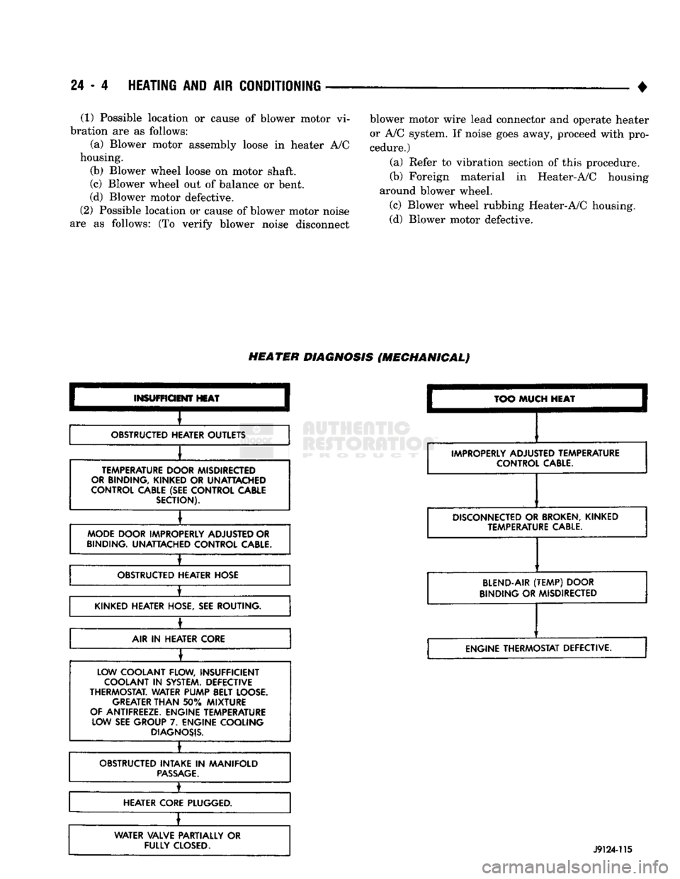
HEATER
DIAGNOSIS
(MECHANICAL)
INSUFFICIENT
HEAT
OBSTRUCTED HEATER OUTLETS
TEMPERATURE DOOR MISDIRECTED
OR BINDING, KINKED
OR
UNATTACHED
CONTROL CABLE (SEE CONTROL CABLE SECTION).
MODE DOOR IMPROPERLY ADJUSTED OR
BINDING. UNATTACHED CONTROL
CABLE.
±
OBSTRUCTED HEATER HOSE
•
KINKED HEATER HOSE, SEE ROUTING.
±
AIR
IN
HEATER CORE
LOW COOLANT FLOW, INSUFFICIENT COOLANT
IN
SYSTEM. DEFECTIVE
THERMOSTAT. WATER PUMP BELT LOOSE. GREATER
THAN
50%
MIXTURE
OF ANTIFREEZE. ENGINE TEMPERATURE LOW SEE GROUP
7.
ENGINE COOLING
DIAGNOSIS.
•
OBSTRUCTED INTAKE
IN
MANIFOLD
PASSAGE.
1_
HEATER CORE PLUGGED.
WATER VALVE PARTIALLY
OR
FULLY
CLOSED.
TOO
MUCH
HEAT
IMPROPERLY ADJUSTED TEMPERATURE CONTROL
CABLE.
DISCONNECTED
OR
BROKEN,
KINKED TEMPERATURE
CABLE.
BLEND-AIR
(TEMP)
DOOR
BINDING OR MISDIRECTED
ENGINE THERMOSTAT DEFECTIVE.
J9124-115
Page 1445 of 1502
24 - 8
HEATING
AND AIR
CONDITIONING
• (e) If compressor clutch cycles 3 to 10 times per
minute with temperature between 20°C-32°C (68°F-
90°F),
the cycling switch is normal. If the compressor
clutch fails to engage, check for continuity in the elec
trical circuit. Above 32°C (90°F) the compressor clutch
may be continuously engaged (non-cycling) due to the
high heat load. This condition is normal.
(4)
Refer to the Evaporator Heater Assembly for
the Removal/Installation procedures.
TESTING
THE
SYSTEM
FOR
LEAKS
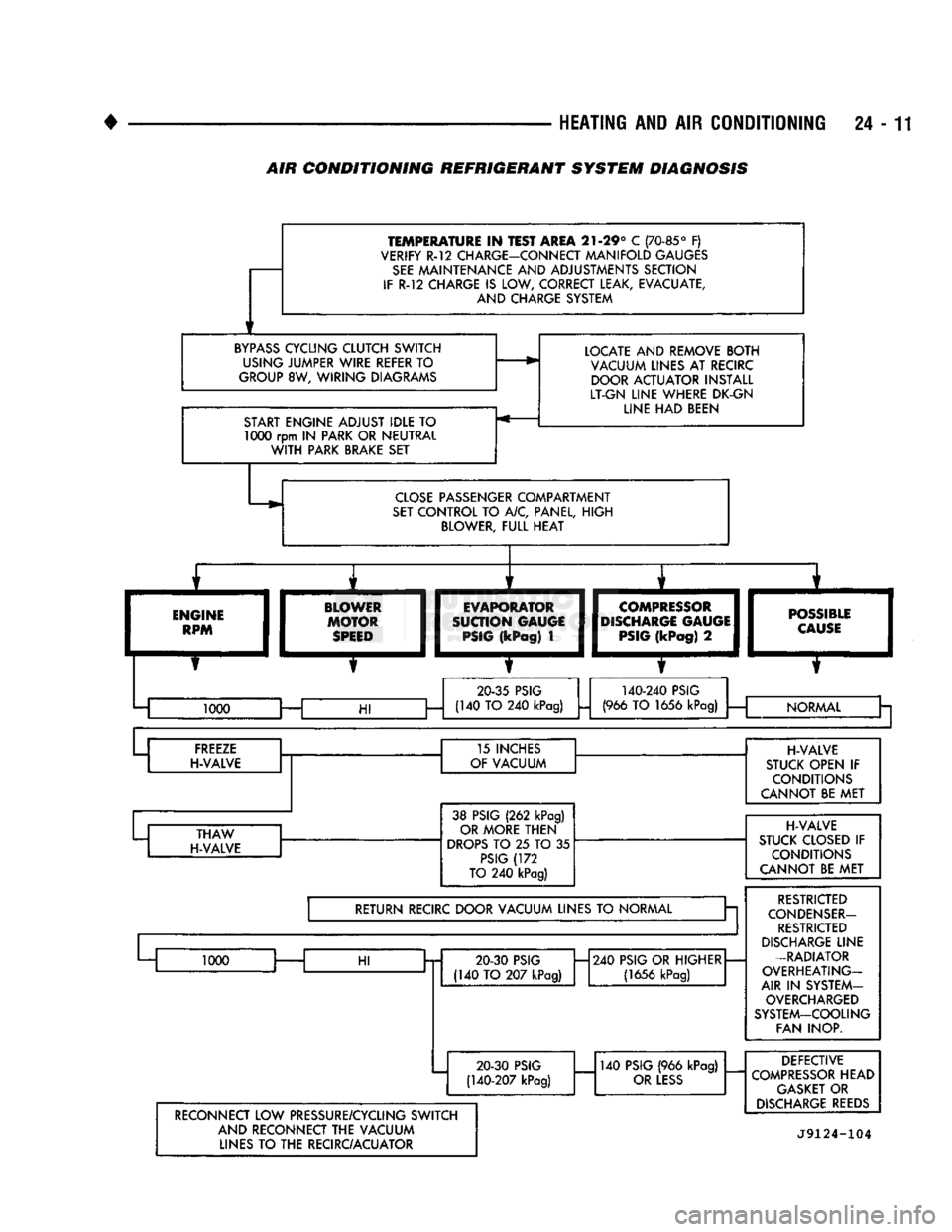
If the air conditioning system is not cooling properly,
check that the refrigerant system is fully charged with
R-12.
Follow the procedures in the Sight Glass Refrig
erant Level Test section of this group.
If the refrigerant system is empty or low in refrig
erant charge, a leak at any of the line fittings or
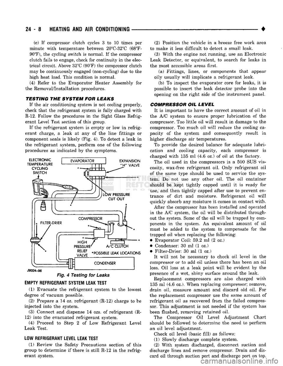
component seals is likely (Fig. 4). To detect a leak in
the refrigerant system, perform one of the following
procedures as indicated by the symptoms.
ELECTRONIC
TEMPERATURE CYCLING
SWITCH
EXPANSION
"H"
VALVE
J9324-96
Fig.
4 Testing for
Leaks
EMPTY REFRIGERANT SYSTEM LEAK TEST
(1) Evacuate the refrigerant system to the lowest
degree of vacuum possible.
(2) Prepare a 14 oz. refrigerant (R-12) charge to be
injected into the system. (3) Connect and dispense 14 ozs. of refrigerant (R-
12) into the evacuated refrigerant system, (4) Proceed to Step 2 of Low Refrigerant Level
Leak Test.
LOW REFRIGERANT LEVEL LEAK TEST
(1) Review the Safety Precautions section of this
group to determine if there is still R-12 in the refrig
erant system. (2) Position the vehicle in a breeze free work area
to make it less difficult to detect a small leak. (3) With the engine not running, use an Electronic
Leak Detector, or equivalent, to search for leaks in
the most accessible areas first.
(a) Fittings, lines, or components that appear
oily usually will implicate a refrigerant leak.
(b) To inspect the evaporator core for leaks, it is
possible to insert the leak detector probe into the opening on the right side of the instrument panel.
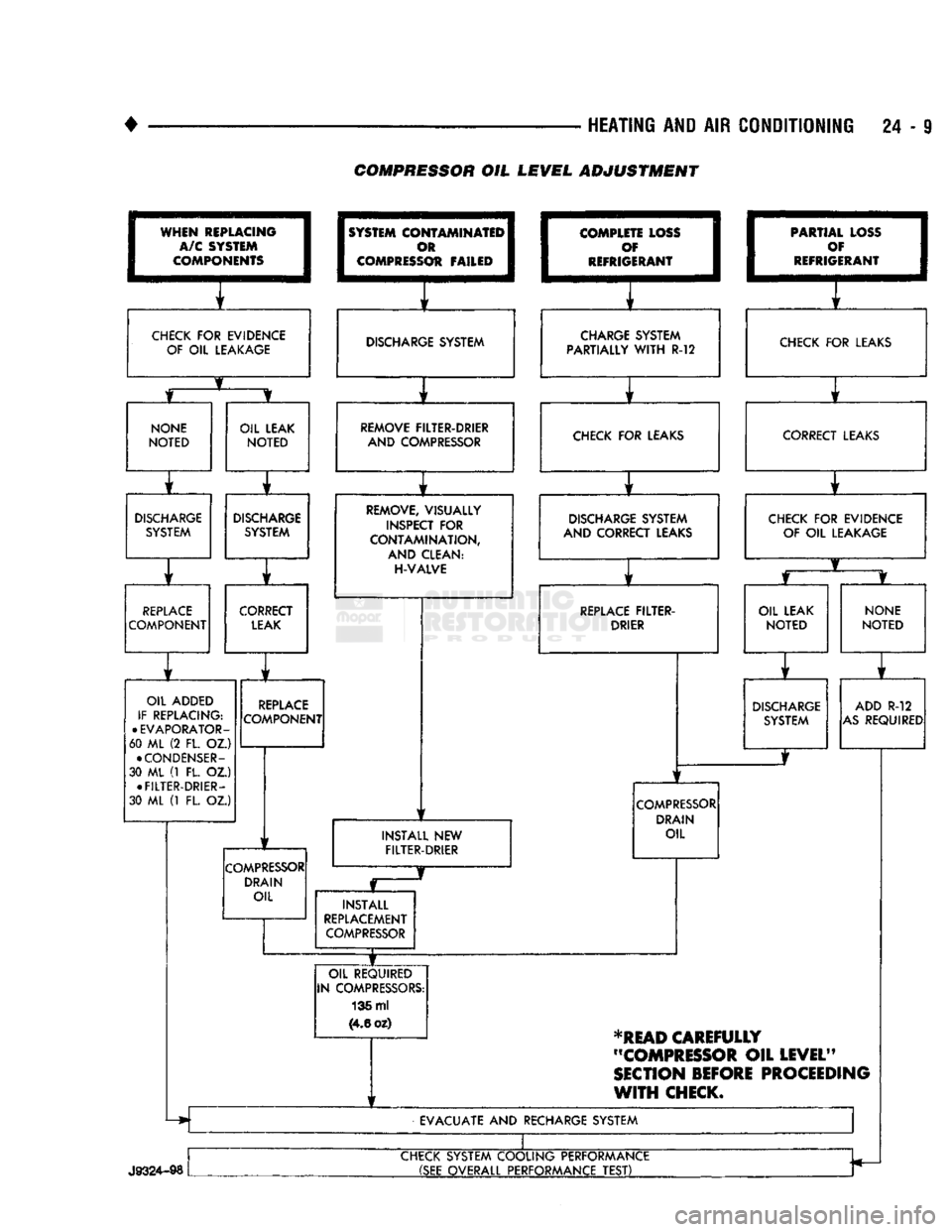
COMPRESSOR OIL LEVEL It is important to have the correct amount of oil in
the A/C system to ensure proper lubrication of the compressor. Too little oil will result in damage to the
compressor. Too much oil will reduce the cooling ca
pacity of the system and consequently result in
higher discharge air temperatures.
To provide the desired balance for adequate lubri
cation and cooling capacity, each compressor is
charged with 135 ml (4.6 oz.) of oil at the factory.
The oil used in the compressors is a 500 SUS vis
cosity, wax-free refrigerant oil. Only refrigerant oil of the same type should be used to service the sys
tem. Do not use any other oil. The oil container should be kept tightly capped until it is ready for
use,
and then tightly capped after use to prevent en
trance of dirt and moisture. Refrigerant oil will quickly absorb any moisture it comes in contact with.
After the compressor has been installed and operated
in the A/C system, the oil will be distributed through
out the system. Some of the oil will be trapped by com
ponents in the system. An equivalent amount of oil
must be added to the system to compensate for the
trapped oil when replacing the following: • Evaporator Coil: 59.2 ml (2 oz.)
• Condenser: 30 ml (1 oz.)
• Filter-Drier: 30 ml (1 oz.) It will not be necessary to check oil level in the
compressor or to add oil unless there has been an oil
loss.
Oil loss at a leak point will be evident by the
presence of a wet, shiny surface around the leak. Replacement compressors are also charged with
135 ml (4.6 oz.). When replacing compressor; remove,
drain oil, measure amount and discard old oil. For
the replacement compressor use the same amount of refrigerant oil as recovered from the failed compressor. This adjustment is not needed if the system has
been flushed, removing retained oil. The Compressor Oil Level Adjustment Chart
should be followed to determine the need to perform
an oil level adjustment. Check oil level (basic fill) as follows: (1) Slowly discharge complete system.
(2) With system discharged, disconnect suction and
discharge lines and remove compressor. Drain and dis card oil through suction port and discharge port on top.
Page 1446 of 1502
•
HEATING AND AIR CONDITIONING 24 - 9 COMPRESSOR OIL LEVEL ADJUSTMENT
WHEN
REPLACING
I
A/C SYSTEM
I
COMPONENTS
1
CHECK
FOR
EVIDENCE
OF
OIL
LEAKAGE
1
SYSTEM
COI
I
c
I COMPRESS
OTAMINATEI^
m 1
Ot FAILED
1
1
f
DISCHARGE SYSTEM
I
COMPLE
1
c
I
REFRIG TE LOSS
I
f 1
ERANT
1
i f
CHARGE SYSTEM
PARTIALLY
WITH
R-12 1
PARTIA
1
c
•
REFRIG L LOSS
1
)¥ I
ERANT
1
f
CHECK
FOR
LEAKS
NONE
NOTED
OIL LEAK
NOTED
r
DISCHARGE
SYSTEM
DISCHARGE
SYSTEM
r ] r
REPLACE
COMPONENT CORRECT
LEAK
OIL ADDED
IF REPLACING:
•
EVAPORATOR-
60 ML (2 FL. OZ.)
•
CONDENSER-
30 ML (1 FL. OZ.) •
FILTER-DRIER-
30 ML (1 FL. OZ.)
REPLACE
COMPONENT
COMPRESSOR
DRAIN OIL REMOVE FILTER-DRIER
AND COMPRESSOR CHECK
FOR
LEAKS
REMOVE, VISUALLY
INSPECT
FOR
CONTAMINATION,
AND CLEAN:
H-VALVE
1
1
DISCHARGE SYSTEM
AND CORRECT LEAKS
1
f
REPLACE
FILTER-
DRIER
INSTALL
NEW
FILTER-DRIER
COMPRESSOR
DRAIN OIL
INSTALL
REPLACEMENT
COMPRESSOR
OIL REQUIRED
IN COMPRESSORS: 136 ml
(4.6
oz) CORRECT LEAKS
CHECK
FOR
EVIDENCE OF
OIL
LEAKAGE
OIL LEAK
NOTED
NONE
NOTED
DISCHARGE
SYSTEM ADD
R-12
AS
REQUIRED
*READ
CAREFULLY
"COMPRESSOR
OIL
LEVEL"
SECTION
BEFORE
PROCEEDING
WITH
CHECK.
EVACUATE
AND
RECHARGE SYSTEM
J9324-98
CHECK SYSTEM COOLING PERFORMANCE
(SEE
OVERALL PERFORMANCE
TEST)
Page 1448 of 1502
HEATING
AND
AIR
CONDITIONING
24 -
TEMPERATURE
IN
TEST AREA
21-29° C
(70-85°
F)
VERIFY R-12 CHARGE-CONNECT MANIFOLD GAUGES
SEE
MAINTENANCE AND ADJUSTMENTS SECTION
IF
R-12
CHARGE
IS
LOW, CORRECT LEAK, EVACUATE, AND CHARGE SYSTEM
BYPASS
CYCLING CLUTCH SWITCH USING JUMPER WIRE REFER
TO
GROUP
8W,
WIRING DIAGRAMS
START ENGINE ADJUST IDLE
TO 1000
rpm
IN
PARK OR NEUTRAL
WITH
PARK BRAKE SET LOCATE AND REMOVE BOTH
VACUUM LINES AT RECIRC DOOR ACTUATOR INSTALL
LT-GN LINE WHERE DK-GN LINE HAD BEEN
CLOSE
PASSENGER COMPARTMENT
SET
CONTROL TO A/C, PANEL, HIGH BLOWER, FULL HEAT
ENGINE
RPM BLOWER
MOTOR
SPEED
I
EVAPORATOR
I
SUCTION GAUGE
I
PSIG
(kPag)
1
COMPRESSOR
DISCHARGE
GAUGE
PSIG
(kPag)
2
—m
POSSIBLE
I
CAUSE
I
20-35
PSIG
140-240
PSIG
1000 —
HI
(140 TO 240
kPag)
(966
TO
1656
kPag)
i
— NORMAL
Cr a
FREEZE
H-VALVE 15 INCHES
OF VACUUM
THAW
H-VALVE 38 PSIG
(262
kPag)
OR MORE THEN
DROPS
TO 25 TO 35
PSIG
(172
TO
240
kPag)
RETURN RECIRC DOOR VACUUM LINES
TO
NORMAL a
1000
HI
20 30
PSIG
(140 TO 207
kPag)
H240
PSIG OR HIGHER
(1656
kPag)
20-30
PSIG
(140-207
kPag)
140
PSIG
(966
kPag)
OR
LESS
H-VALVE
STUCK OPEN
IF
CONDITIONS
CANNOT BE MET
H-VALVE
STUCK CLOSED
IF
CONDITIONS
CANNOT BE MET
RESTRICTED
CONDENSER-
RESTRICTED
DISCHARGE
LINE
-RADIATOR
OVERHEATING-
AIR
IN
SYSTEM- OVERCHARGED
SYSTEM-COOLING FAN INOP.
RECONNECT LOW PRESSURE/CYCLING SWITCH AND RECONNECT THE VACUUM LINES
TO
THE RECIRC/ACUATOR DEFECTIVE
COMPRESSOR
HEAD
GASKET
OR
DISCHARGE
REEDS
J9124-104
AIR
CONDITIONING REFRIGERANT SYSTEM DIAGNOSIS
Page 1458 of 1502
•
HEATING
AND AIR
CONDITIONING
24 - 21 (a) Loosen both test hoses at the manifold gauge
set. Tighten the hoses as soon as the air is purged. (b) Loosen charging hose connection at manifold
gauge set. This will purge air from the charging
hose.
Tighten connection as soon as air is purged.
(9) With vehicle windows open and hood up, oper
ate engine at 1,300 RPM. (10) Place air conditioner control on A/C and place
the fan switch on high. (11) If necessary, block the condenser to maintain
a discharge pressure of 1 550-1 725 kPag (225-250
psig).
System must be charged through the evapora
tor suction service ports as follows:
(a) Slowly open the suction service gauge valve.
Meter flow of refrigerant by adjusting the suction service gauge valve so the pressure registered at
the suction service gauge does not exceed 345 kPag
COMPRESSOR
J
(50
psig). Keep refrigerant container upright.
(b) Add refrigerant gas until there is no foam visi
ble at the sight glass. As soon as all foam clears, note the weight registered on the refrigerant scale.
(c) Watch the refrigerant weighing scale and add
437 g (14 oz.) of refrigerant (equivalent to 1 can).
(d) Close the suction gauge valve.
CAUTION:
TOO
much
refrigerant
in the
system
can
cause
abnormally high discharge pressures. Care
must
be
used
so the
exact recommended amount
of
refrigerant
is
added
after
foam clears
in the
sight
glass.
(e) Close dispensing manifold valve. Remove test
hoses and adapters from the service ports of com
pressor and install protective caps at service ports.
RVICE (SD-709)
INDEX
page
Compressor
21
Compressor
Shaft Seal
.................... 25
The A/C system uses a 7 piston design Sanden SD-
709 compressor. Designated the SD-709, the compres
sor is mounted on the front right side of the engine
and is driven by a serpentine belt.
System lubrication is provided by 135cc ±15cc (4.6
cu. in. ±0.5 cu. in.) of 500 viscosity refrigerant oil.
The clutch used on the compressor consists of 3 ba
sic components:
(1) The pulley.
(2) The front plate. (3) The field coil.
The pulley and field coil are attached to the front
head of the compressor with snap rings. The hub is keyed to the compressor shaft and is retained on the
shaft with a self-locking nut. Special service tools are
required to remove and install the clutch plate on
the compressor shaft.
COMPRESSOR
REMOVAL
(1) Disconnect the negative cable from the battery.
(2) Disconnect the clutch lead wire.
(3) Remove the discharge and inlet (suction) ser
vice valves from the compressor. Plug or tape all the
openings.
(4) Refer to Group 7, Cooling System and remove
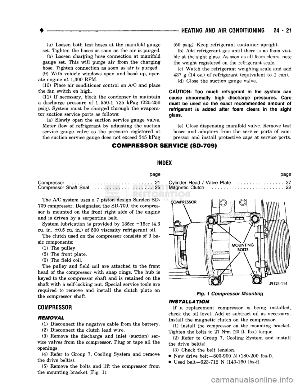
the drive belt(s). (5) Remove the bolts and lift the compressor from
the mounting bracket (Fig. 1).
page
Cylinder Head
/
Valve Plate
27
Magnetic
Clutch
22
Fig.
1
Compressor
Mounting
INSTALLATION
If a replacement compressor is being installed,
check the oil level. Add or subtract oil as necessary.
Install the magnetic clutch on the compressor.
(1) Install the compressor on the mounting bracket.
Tighten the bolts to 27 N*m (20 ft. lbs.) torque.
(2) Refer to Group 7, Cooling System and install
the drive belt(s).
(3) Check the belt tension.
@ New drive belt-800-900 N (180-200 lbs-f).
• Used belt-623-712 N (140-160 lbs-f).
Page 1474 of 1502
•
Fig.
12
Blower
Wheel
(7) Install the 3 arms. Install nut that attaches 3
door arms to doors on the top cover of the unit (Fig.
11).
INSTALLATION
(1) Install the evaporator heater assembly. Plastic
instrument panel may have to be flexed outward.
(2) Install and tighten the screw that retains the
evaporator heater assembly to cowl side sheet metal.
(3) Install the retaining nuts on engine side.
(4) Connect vacuum lines on engine side.
(5) Install blower motor connector on engine side.
(6) Remove wiring connector from resistor block.
(7) Connect vacuum lines from extension on con
trol unit and attach vacuum lines to defroster duct (Fig. 10).
(8) Connect temperature control cable to unit
through glove box. (9) Install floor air distribution duct.
(10) Install center distribution duct.
(11) Attach radio ground strap. (12) Remove right half of lower reinforcement by
removing screws attaching it to the instrument panel and the screw attaching it to the cowl side trim
panel. (13) Install ash receiver.
(14) Install structural brace through glove box
opening. Install screws and loosen nuts. (15) Install glove box by installing mounting
screws. (16) Install right cowl side trim panel, if so
equipped. (17) Position transfer case and/or gear shift levers.
(18) Remove plugs from heater hoses and unit. In
stall condensate tube (Fig. 9). (19) Connect refrigerant and heater lines to unit
on engine side.
} (20) Connect the negative cable to the battery. (21) Fill the cooling system (refer to Group 7, Cool
ing System). (22) Evacuate and charge the system.
(23) Check operation of all controls and perfor
mance of the A/C system.
HEATING
AND AIR
CONDITIONING
24 - 37
'H"
VALVE
Fig.
13
Expansion
(H)
Valve
Assembly
ELECTRONIC
TEMPERATURE
CYCLING
SWITCH
REMOVAL
(1) Remove the electrical wires to the switch.
(2) Rotate switch counterclockwise to remove from
pressure switch port. (3) Remove and discard old O-ring.
INSTALLATION
(1) Install new O-ring. Refrigerant oil must be ap
plied to the new O-ring.
(2) Rotate switch clockwise to install on suction
line pressure switch port. Tighten switch to 5.65 N#m (50 in. lbs.) torque.
CAUTION:
Power
tools
should
not be
used
for in
stallation
of the switch. The
possibility
of stripping
the
switch
threads
occurs
above
5.88 N*m (52 in.
lbs.)
torque.
(3) Connect wires. (4) Verify operation.
EXPANSION
(H)
VALVE
REMOVAL
The system must be completely discharged before
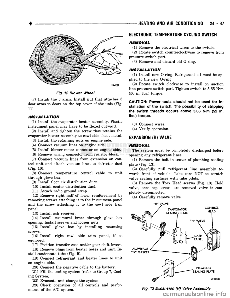
opening any refrigerant lines. (1) Remove the bolt in center of plumbing sealing
plate (Fig. 13).
(2) Carefully pull refrigerant line assembly to
wards front of vehicle. Take care NOT to scratch valve sealing surfaces with tube pilots.
(3) Remove the Torx Head screws (Fig. 13). Hold
valve, once cap screws are removed valve is com
pletely disconnected.
(4) Carefully remove valve.