1993 DODGE TRUCK cooling
[x] Cancel search: coolingPage 744 of 1502
•
5.9L
(DIESEL) ENGINE 9 - 139
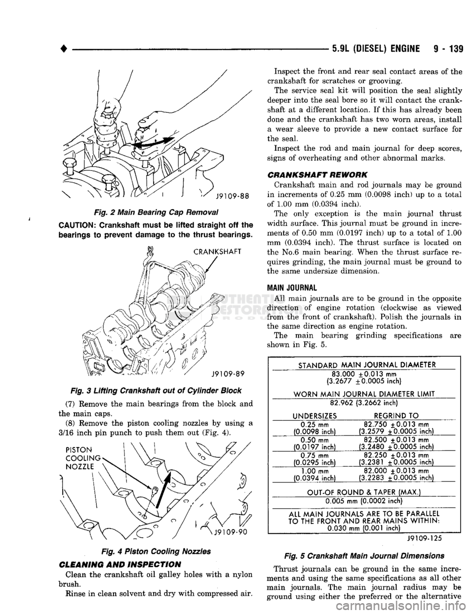
Fig.
2 Main Beating Cap
Removal
CAUTION:
Crankshaft must be
lifted
straight
off the
bearings
to
prevent
damage
to the
thrust
bearings.
Fig.
3 Lifting Crankshaft out of Cylinder
Block
(7)
Remove the main bearings from the block and
the main caps. (8) Remove the piston cooling nozzles by using a
3/16 inch pin punch to push them out (Fig. 4).
Fig.
4
Piston
Cooling
Nozzles
CLEANING
AND
INSPECTION
Clean the crankshaft oil galley holes with a nylon
brush. Rinse in clean solvent and dry with compressed air. Inspect the front and rear seal contact areas of the
crankshaft for scratches or grooving. The service seal kit will position the seal slightly
deeper into the seal bore so it will contact the crank
shaft at a different location. If this has already been
done and the crankshaft has two worn areas, install
a wear sleeve to provide a new contact surface for
the seal.
Inspect the rod and main journal for deep scores,
signs of overheating and other abnormal marks.
CRANKSHAFT
REWORK
Crankshaft main and rod journals may be ground
in increments of 0.25 mm (0.0098 inch) up to a total
of 1.00 mm (0.0394 inch). The only exception is the main journal thrust
width surface. This journal must be ground in incre ments of 0.50 mm (0.0197 inch) up to a total of 1.00
mm (0.0394 inch). The thrust surface is located on
the No.6 main bearing. When the thrust surface re quires grinding, the main journal must be ground to
the same undersize dimension.
MAIN
JOURNAL
All main journals are to be ground in the opposite
direction of engine rotation (clockwise as viewed
from the front of crankshaft). Polish the journals in
the same direction as engine rotation.
The main bearing grinding specifications are
shown in Fig. 5.
STANDARD
MAIN
JOURNAL
DIAMETER
83.000 +0.013 mm
(3.2677 ±0.0005 inch)
WORN
MAIN
JOURNAL
DIAMETER
LIMIT
82.962 (3.2662
inch)
UNDERSIZES
REGRIND
TO
0.25 mm
(0.0098
inch)
82.750 ±0.013 mm
(3.2579 ±0.0005
inch)
0.50 mm
(0.0197
inch)
82.500 +0.013 mm
(3.2480 +0.0005
inch)
0.75 mm
(0.0295
inch)
82.250 +0.013 mm
(3.2381 ±0.0005
inch)
1.00 mm
(0.0394 inch) 82.000 +0.013 mm
(3.2283 ±0.0005 inch)
OUT-OF
ROUND
&
TAPER
(MAX.)
0.005 mm (0.0002 inch)
ALL
MAIN
JOURNALS
ARE
TO
BE
PARALLEL
TO
THE
FRONT
AND
REAR
MAINS
WITHIN:
0.030
mm
(0.001 inch)
J9109-125
Fig.
5 Crankshaft Main
Journal
Dimensions
Thrust journals can be ground in the same incre
ments and using the same specifications as all other main journals. The main journal radius may be ground using either the preferred or the alternative
Page 749 of 1502
9 - 146 5.9L (DIESEL) ENGINE
•
DIAL
INDICATOR
CYLINDER BLOCK
GASKET
J9109-97
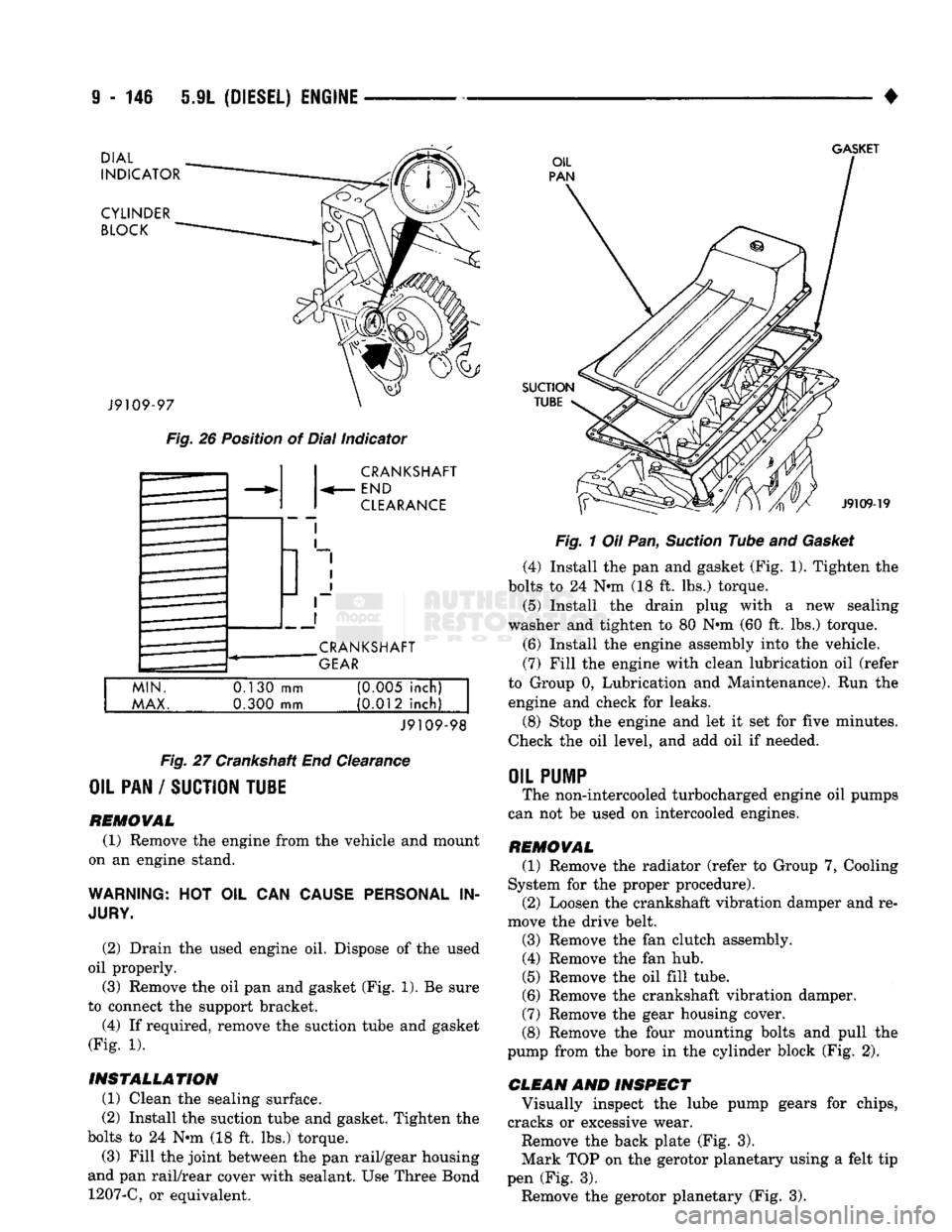
Fig.
26 Position of Dial Indicator CRANKSHAFT
END
CLEARANCE
CRANKSHAFT
GEAR
MIN.
MAX.
0.130
mm
0.300 mm (0M5 inch)
(0.012 inch)
J9109-98
Fig.
27 Crankshaft End Clearance
OIL PAN / SUCTION TU1E
REMOVAL (1) Remove the engine from the vehicle and mount
on an engine stand.
WARNING:
HOT OIL CAN
CAUSE PERSONAL
IN
JURY.
(2) Drain the used engine oil. Dispose of the used
oil properly. (3) Remove the oil pan and gasket (Fig. 1). Be sure
to connect the support bracket.
(4) If required, remove the suction tube and gasket
(Fig. 1).
INSTALLATION (1) Clean the sealing surface.
(2) Install the suction tube and gasket. Tighten the
bolts to 24 Nin (18 ft. lbs.) torque.
(3) Fill the joint between the pan rail/gear housing
and pan rail/rear cover with sealant. Use Three Bond 1207-C, or equivalent.
SUCTION
TUBE
J9109-19
Fig.
1 Oil Pan,
Suction
Tube and
Gasket
(4) Install the pan and gasket (Fig. 1). Tighten the
bolts to 24 N-m (18 ft. lbs.) torque.
(5) Install the drain plug with
a
new sealing
washer and tighten to 80 Nnn (60 ft. lbs.) torque.
(6) Install the engine assembly into the vehicle.
(7) Fill the engine with clean lubrication oil (refer
to Group 0, Lubrication and Maintenance). Run the engine and check for leaks.
(8) Stop the engine and let it set for five minutes.
Check the oil level, and add oil if needed.
OIL
PUMP
The non-intercooled turbocharged engine oil pumps
can not be used on intercooled engines.
REMOVAL (1) Remove the radiator (refer to Group 7, Cooling
System for the proper procedure). (2) Loosen the crankshaft vibration damper and re
move the drive belt.
(3) Remove the fan clutch assembly. (4) Remove the fan hub.
(5) Remove the oil fill tube.
(6) Remove the crankshaft vibration damper.
(7) Remove the gear housing cover.
(8) Remove the four mounting bolts and pull the
pump from the bore in the cylinder block (Fig. 2).
CLEAN AND INSPECT Visually inspect the lube pump gears for chips,
cracks or excessive wear.
Remove the back plate (Fig. 3).
Mark TOP on the gerotor planetary using a felt tip
pen (Fig. 3). Remove the gerotor planetary (Fig. 3).
Page 751 of 1502
9
- 148 5.9L
(DIESEL) ENGINE
• Make sure the idler gear pin is installed in the lo
cating bore in the cylinder block. (2) Install the pump. Tighten the oil pump mount
ing bolts in two steps and in the sequence shown (Fig. 2).
• Step
1—Tighten
to 5 N«m (44 in. lbs.) torque.
• Step 2-Tighten to 24 N*m (18 ft. lbs.) torque. (3) The back plate on the pump seats against the
bottom of the bore in the cylinder block. When the
pump is correctly installed, the flange on the pump will not touch the cylinder block.
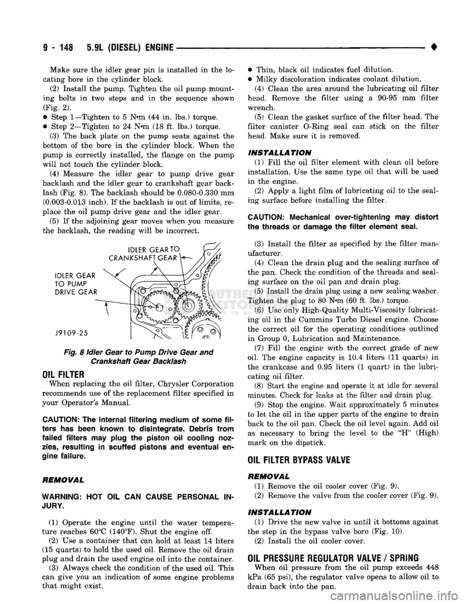
(4) Measure the idler gear to pump drive gear
backlash and the idler gear to crankshaft gear back lash (Fig. 8). The backlash should be 0.080-0.330 mm (0.003-0.013 inch). If the backlash is out of limits, re
place the oil pump drive gear and the idler gear.
(5) If the adjoining gear moves when you measure
the backlash, the reading will be incorrect.
Fig.
8
idler
Gear to
Pump
Drive Gear and Crankshaft Gear
Backlash
OIL FILTER
When replacing the oil filter, Chrysler Corporation
recommends use of the replacement filter specified in
your Operator's Manual.
CAUTION:
The
internal filtering medium
of
some
fil
ters
has
been known
to
disintegrate. Debris from
failed filters
may
plug
the
piston
oil
cooling noz
zles,
resulting
in
scuffed pistons
and
eventual
en
gine
failure.
REMOVAL
WARNING:
HOT OIL CAN
CAUSE PERSONAL
IN
JURY.
(1) Operate the engine until the water tempera
ture reaches 60°C (140°F). Shut the engine off.
(2) Use a container that can hold at least 14 liters
(15 quarts) to hold the used oil. Remove the oil drain
plug and drain the used engine oil into the container.
(3) Always check the condition of the used oil. This
can give you an indication of some engine problems
that might exist. • Thin, black oil indicates fuel dilution.
• Milky discoloration indicates coolant dilution.
(4) Clean the area around the lubricating oil filter
head. Remove the filter using a 90-95 mm filter
wrench.
(5) Clean the gasket surface of the filter head. The
filter canister O-Ring seal can stick on the filter
head. Make sure it is removed.
INSTALLATION (1) Fill the oil filter element with clean oil before
installation. Use the same type oil that will be used
in the engine.
(2) Apply a light film of lubricating oil to the seal
ing surface before installing the filter.
CAUTION:
Mechanical over-tightening
may
distort
the threads
or
damage
the filter
element seal.
(3) Install the filter as specified by the filter man
ufacturer. (4) Clean the drain plug and the sealing surface of
the pan. Check the condition of the threads and seal ing surface on the oil pan and drain plug.
(5) Install the drain plug using a new sealing washer.
Tighten the plug to 80 N-m (60 ft. lbs.) torque.
(6) Use only High-Quality Multi-Viscosity lubricat
ing oil in the Cummins Turbo Diesel engine. Choose
the correct oil for the operating conditions outlined in Group 0, Lubrication and Maintenance.
(7) Fill the enginfe with the correct grade of new
oil.
The engine capacity is i0.4 liters (11 quarts) in
the crankcase and 0.95 liters (1 quart) in the lubri cating oil filter. (8) Start the engine and operate it at idle for several
minutes. Check for leaks at the filter and drain plug.
(9) Stop the engine. Wait approximately 5 minutes
to let the oil in the upper parts of the engine to drain
back to the oil pan. Check the oil level again. Add oil as necessary to bring the level to the "H" (High)
mark on the dipstick.
OIL FILTER
BYPASS
VALWE
REMOVAL
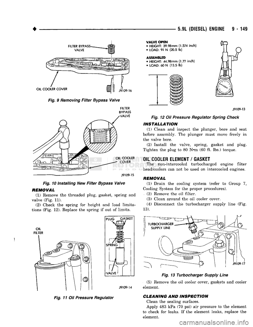
(1) Remove the oil cooler cover (Fig. 9). (2) Remove the valve from the cooler cover (Fig. 9).
INSTALLATION (1) Drive the new valve in until it bottoms against
the step in the bypass valve bore (Fig. 10).
(2) Install the oil cooler cover.
OIL PRESSURE REGULATOR VALVE
/
SPRING
When oil pressure from the oil pump exceeds 448
kPa (65 psi), the regulator valve opens to allow oil to
drain back into the pan.
Page 752 of 1502
5.9L
(DIESEL) ENGINE
9 - 149
FILTER
BYPASS-
VALVE
OIL COOLER COVER
Fig. 9
Removing
Filter
Bypass
Valve
n
J9109-16
FILTER
BYPASS
VALVE OIL COOLER
COVER
J9109-15
Fig. 10 Installing New
Filter
Bypass
Valve
REMOVAL
(1) Remove the threaded plug, gasket, spring and
valve (Fig. 11). (2) Check the spring for height and load limita
tions (Fig. 12). Replace the spring if out of limits.
OIL
FILTER PLUG GASKET
SPRING
J9109-14
Fig. 11 Oil
Pressure
Regulator
VALVE OPEN
•
HEIGHT:
39.98mm
(1.574
inch)
•
LOAD:
91 N (20.5 lb)
ASSEMBLED
•
HEIGHT:
44.98mm (1.77 inch) •
LOAD:
60 N (13.5 lb)
J9109-13
Fig. 12 Oil
Pressure
Regulator
Spring
Check
INSTALLATION
(1) Clean and inspect the plunger, bore and seat
before assembly. The plunger must move freely in
the valve bore.
(2) Install the valve, spring, gasket and plug.
Tighten the plug to 80 N*m (60 ft. lbs.) torque.
OIL COOLER ELEMENT
/
GASKET
The non-intercooled turbocharged engine filter
head/coolers can not be used on intercooled engines.
REMOVAL
(1) Drain the cooling system (refer to Group 7,
Cooling System for the proper procedures).
(2) Remove the oil filter.
(3) Clean around the oil cooler cover. (4) Disconnect the turbocharger supply line (Fig.
13).
J9109-17
Fig. 13 Turbocharger
Supply
Line
(5) Remove the oil cooler cover, gaskets and cooler
element.
CLEANING
AND
INSPECTION
Clean the sealing surfaces.
Apply 483 kPa (70 psi) air pressure to the element
to check for leaks. If the element leaks, replace the element.
Page 756 of 1502
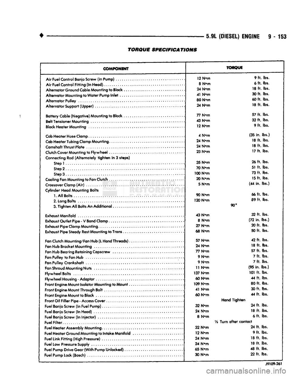
5.9L
(DIESEL)
ENGINE
9-153
TORQUE
SPECIFICATIONS
COMPONENT
Air
Fuel
Control
Banjo Screw (In Pump) ....
Air
Fuel
Control
Fitting
(In
Head)
Alternator
Ground Cable Mounting to
Block
Alternator
Mounting to
Water
Pump
Inlet
..
Alternator
Pulley
Alternator
Support
(Upper)
Battery
Cable
(Negative)
Mounting to Block ,
Belt
Tensioner
Mounting
Block
Heater
Mounting
Cab
Heater
Hose
Clamp
Cab
Heater
Tubing
Clamp Mounting.......
Camshaft
Thrust
Plate
Clutch Cover Mounting to
Flywheel
...
Connecting Rod
(Alternately
tighten
in 3 steps) Step 1
Step 2
Step 3 .
Cooling Fan Mounting to
Fan
Clutch
Crossover
Clamp (Air)
Cylinder
Head
Mounting Bolts
1.
All
Bolts....
2.
Long
Bolts
.........
3.
Tighten
All
Bolts
An
Additional
Exhaust
Manifold
Exhaust
Outlet
Pipe
- V
Band
Clamp
Exhaust
Pipe
Clamp Mounting
Exhaust
Pipe
Steady
Rest
Mounting to Trans .
Fan
Clutch Mounting/Fan Hub
(L
Hand
Threads)..
Fan Hub
Bracket
Mounting
Fan Hub Bearing
Retaining
Capscrew
Fan
Pulley
to
Fan
Hub
Fan
Pulley
Crankshaft .
Fan
Shroud
Mounting Nuts
Flywheel
Bolts
Flywheel
Housing
- Adaptor
Front
Engine
Mount Isolator Mounting to Mount..
Front
Engine
Mount Through Bolt
Front
Engine
Mount to Block
Front
Oil
Filler
Pipe
-
Access
Cover
Fuel
Banjo Screw (In
Fuel
Pump)
Fuel
Banjo Screw (In
Head)
Fuel
Banjo Screw (In
Injector)
Fuel
Filter
Fuel
Heater
Assembly
Mounting
Fuel
Heater
Ground Mounting to
Intake
Manifold
Fuel
Link
Fitting
(High Pressure)
Fuel
Low Pressure Supply
Fuel
Pump
Drive
Gear
(With
Pump
Unlocked)
Fuel
Pump Lock (Bosch)
TORQUE
12 N-m 9 ft. lbs.
8 N-m 6 ft. lbs.
24 N-m 18 ft. lbs.
41 N*m 30 ft. lbs.
80 N-m 60 ft. lbs.
24 N-m 18 ft. lbs.
77 N-m 57 ft. lbs.
43 N-m 32 ft. lbs.
12 N-m 9 ft. lbs.
4 N-m (35 in. lbs.)
24 N-m 18 ft. lbs.
24 N-m 18 ft. lbs.
23 N-m 17 ft. lbs.
35 N-m 26 ft. lbs.
70 N-m 51 ft. lbs.
100 N-m 73 ft. lbs.
20 N-m 15 ft. lbs.
5
N-m (44 in. lbs.)
90 N-m 66 ft. lbs.
120 N-m 89 ft. lbs.
90°
43 N-m 32 ft. lbs.
8 N-m (72 in. lbs.)
27 N-m 20 ft. lbs.
68 N-m 50 ft. lbs.
57 N-m 42 ft. lbs.
24 N-m 18 ft. lbs.
77 N-m 57 ft. lbs.
9 N-m 7 ft. lbs.
9 N-m 7 ft. lbs.
11 N-m (95 in. lbs.)
137 N-m 101 ft. lbs.
60 N-m 44 ft. lbs.
109 N-m 80 ft. lbs.
41 N-m 30 ft. lbs.
60 N-m 44 ft. lbs.
Hand
Tighten
32 N-m 24 ft. lbs.
24 N-m 18 ft. lbs.
8 N-m 6 ft. lbs.
Vi
Turn
after
contact
32 N-m 24 ft. lbs.
12 N-m 9 ft. lbs.
24 N-m 18 ft. lbs.
24 N-m 18 ft. lbs.
65 N-m 48 ft. lbs.
30 N-m 22 ft. lbs.
J9109-261
Page 772 of 1502
•
EXHAUST SYSTEM
AND
INTAKE MANIFOLD
11-13
TIGHTENING
TORQUE
23
N-m
(200
IN. LBS.)
7
N-m
(65
IN. LBS.)
5 N-m
(40
IN. LBS.)
HEAT
SHIELD CATALYTIC
CONVERTER
LOWER HEAT SHIELD HEAT
SHIELD UPPER
HEAT
SHIELD
CROSSMEMBER
SKID
PLATE
UPPER HEAT SHIELD
(6 IN.
RAIL) CONED WASHER
UPPER HEAT SHIELD
(7 IN.
RAIL)
J9211-21
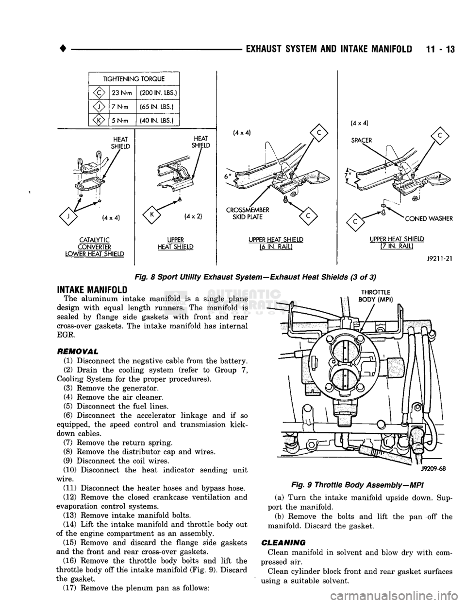
Fig.
8
Sport
Utility
Exhaust
System—Exhaust
Heat
Shields
(3 of 3)
INTAKE MANIFOLD
The aluminum intake manifold is a single plane
design with equal length runners. The manifold is sealed by flange side gaskets with front and rear
cross-over gaskets. The intake manifold has internal
EGR.
REMOVAL
(1) Disconnect the negative cable from the battery.
(2) Drain the cooling system (refer to Group 7,
Cooling System for the proper procedures).
(3) Remove the generator.
(4) Remove the air cleaner.
(5) Disconnect the fuel lines.
(6) Disconnect the accelerator linkage and if so
equipped, the speed control and transmission kick-
down cables.
(7) Remove the return spring.
(8) Remove the distributor cap and wires.
(9) Disconnect the coil wires.
(10) Disconnect the heat indicator sending unit
wire.
(11) Disconnect the heater hoses and bypass hose.
(12) Remove the closed crankcase ventilation and
evaporation control systems. (13) Remove intake manifold bolts.
(14) Lift the intake manifold and throttle body out
of the engine compartment as an assembly. (15) Remove and discard the flange side gaskets
and the front and rear cross-over gaskets.
(16) Remove the throttle body bolts and lift the
throttle body off the intake manifold (Fig. 9). Discard
the gasket. (17) Remove the plenum pan as follows:
THROTTLE
BODY
(MPI)
J9209-68
Fig.
9
Throttle
Body Assembly—MPI
(a) Turn the intake manifold upside down. Sup
port the manifold.
(b) Remove the bolts and lift the pan off the
manifold. Discard the gasket.
CLEANING
Clean manifold in solvent and blow dry with com
pressed air.
Clean cylinder block front and rear gasket surfaces
using a suitable solvent.
Page 774 of 1502
EXHAUST SYSTEM
AND
INTAKE MANIFOLD
11-15
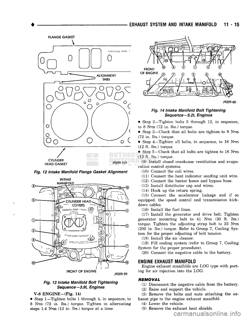
FLANGE GASKET
o
o
CYLINDER
HEAD GASKET
J9209-101
Fig. 12 Intake Manifold Flange Gasket Alignment
®— INTAKE
MANIFOLD
FRONT OF
ENGINE
J9209-59
Fig. 13 Intake Manifold Bolt Tightening Sequence—3.9L Engines
V-8 ENGINE—(Fig* 14)
• Step
1—Tighten
bolts 1 through 4, in sequence, to 8 Nun (72 in. lbs.) torque. Tighten in alternating
steps 1.4 Nun (12 in. lbs.) torque at a time.
FRONT
OF ENGINE
J9209-60
Fig. 14 Intake Manifold Bolt Tightening Sequence—5.2L Engines
• Step 2—Tighten bolts 5 through 12, in sequence,
to 8 Nun (72 in. lbs.) torque. • Step 3—Check that all bolts are tighten to 8 Nun (72 in. lbs.) torque.
• Step 4—Tighten all bolts, in sequence, to 16 Nun (12 ft. lbs.) torque.
• Step 5—Check that all bolts are tighten to 16 Nun (12 ft. lbs.) torque.
(9) Install closed crankcase ventilation and evapo
ration control systems. (10) Connect the coil wires.
(11) Connect the heat indicator sending unit wire.
(12) Connect the heater hoses and bypass hose.
(13) Install distributor cap and wires.
(14) Hook up the return spring.
(15) Connect the accelerator linkage and if so
equipped, the speed control and transmission kick-
down cables. (16) Install the fuel lines,
(17) Install the generator and drive belt. Tighten
generator mounting bolt to 41 Nun (30 ft. lbs.)
torque. Tighten the adjusting strap bolt to 23 Nun (200 in. lbs.) torque. Refer to Group 7, Cooling Sys
tem for the proper adjusting of belt tension. (18) Install the air cleaner. (19) Fill cooling system (refer to Group 7, Cooling
System for the proper procedure). (20) Connect the negative cable to the battery.
ENGINE EXHAUST MANIFOLD
Engine exhaust manifolds are LOG type with port
ing for air injection into the LOG.
REMOVAL (1) Disconnect the negative cable from the battery.
(2) Raise and support the vehicle.
(3) Remove the bolts and nuts attaching the ex
haust pipe to the engine exhaust manifold. (4) Lower the vehicle. (5) Remove the exhaust heat shields.
Page 874 of 1502
•
FUEL
SYSTEM
14 - 55
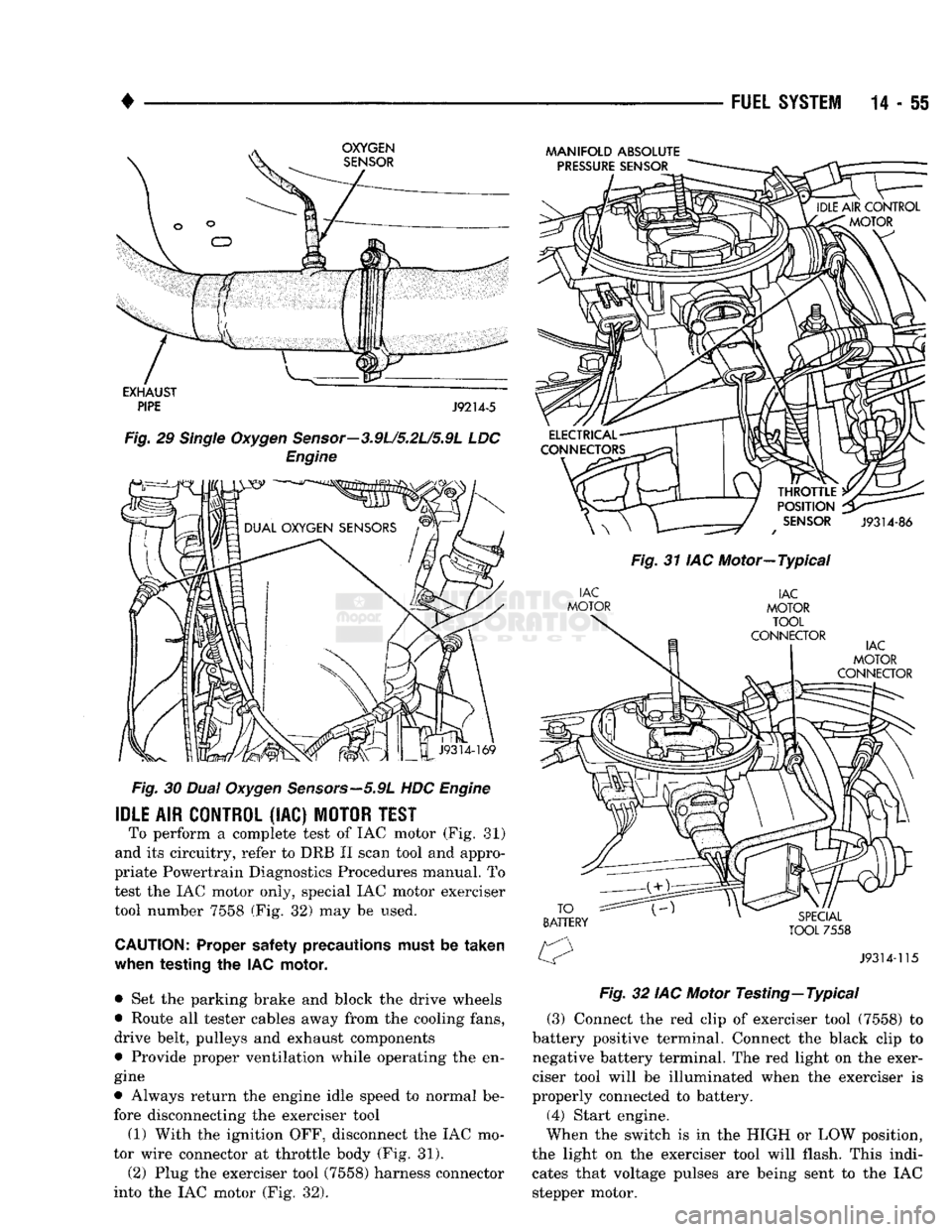
Fig.
30
Dual
Oxygen
Sensors—5.9L
HDC
Engine
IDLE
AIR
CONTROL
(IAC)
MOTOR
TEST
To perform a complete test of IAC motor (Fig. 81)
and its circuitry, refer to DRB II scan tool and appro
priate Powertrain Diagnostics Procedures manual. To
test the IAC motor only, special IAC motor exerciser tool number 7558 (Fig. 32) may be used.
CAUTION:
Proper safety precautions must be
taken
when
testing
the IAC
motor,
• Set the parking brake and block the drive wheels
• Route all tester cables away from the cooling fans,
drive belt, pulleys and exhaust components
• Provide proper ventilation while operating the en
gine
• Always return the engine idle speed to normal be
fore disconnecting the exerciser tool
(1) With the ignition OFF, disconnect the IAC mo
tor wire connector at throttle body (Fig. 31).
(2) Plug the exerciser tool (7558) harness connector
into the IAC motor (Fig. 32).
MANIFOLD
ABSOLUTE
Fig.
31 IAC Motor—Typical
Fig.
32 IAC Motor
Testing—
Typical
(3) Connect the red clip of exerciser tool (7558) to
battery positive terminal. Connect the black clip to
negative battery terminal. The red light on the exer
ciser tool will be illuminated when the exerciser is
properly connected to battery. (4) Start engine.
When the switch is in the HIGH or LOW position,
the light on the exerciser tool will flash. This indi cates that voltage pulses are being sent to the IAC
stepper motor.