1993 DODGE TRUCK cooling
[x] Cancel search: coolingPage 622 of 1502
•
3.9L ENGINE
9 - 17
3.9L
ENGINE SERVICE PROCEDURES
INDEX
page
Camshaft
31
Crankshaft
38
Crankshaft Main Bearings
39
Crankshaft Rear
Oil
Seals
. 40
Cylinder Block
41
Cylinder Head Cover
. , 21
Cylinder Heads
. 22
Distributor
33
Engine
Assembly .........................
20
Engine
Front Mounts
17
Engine
Rear Mount
18
Front Crankshaft
Oil
Seal Replacement ........
31
GENERAL INFORMATION
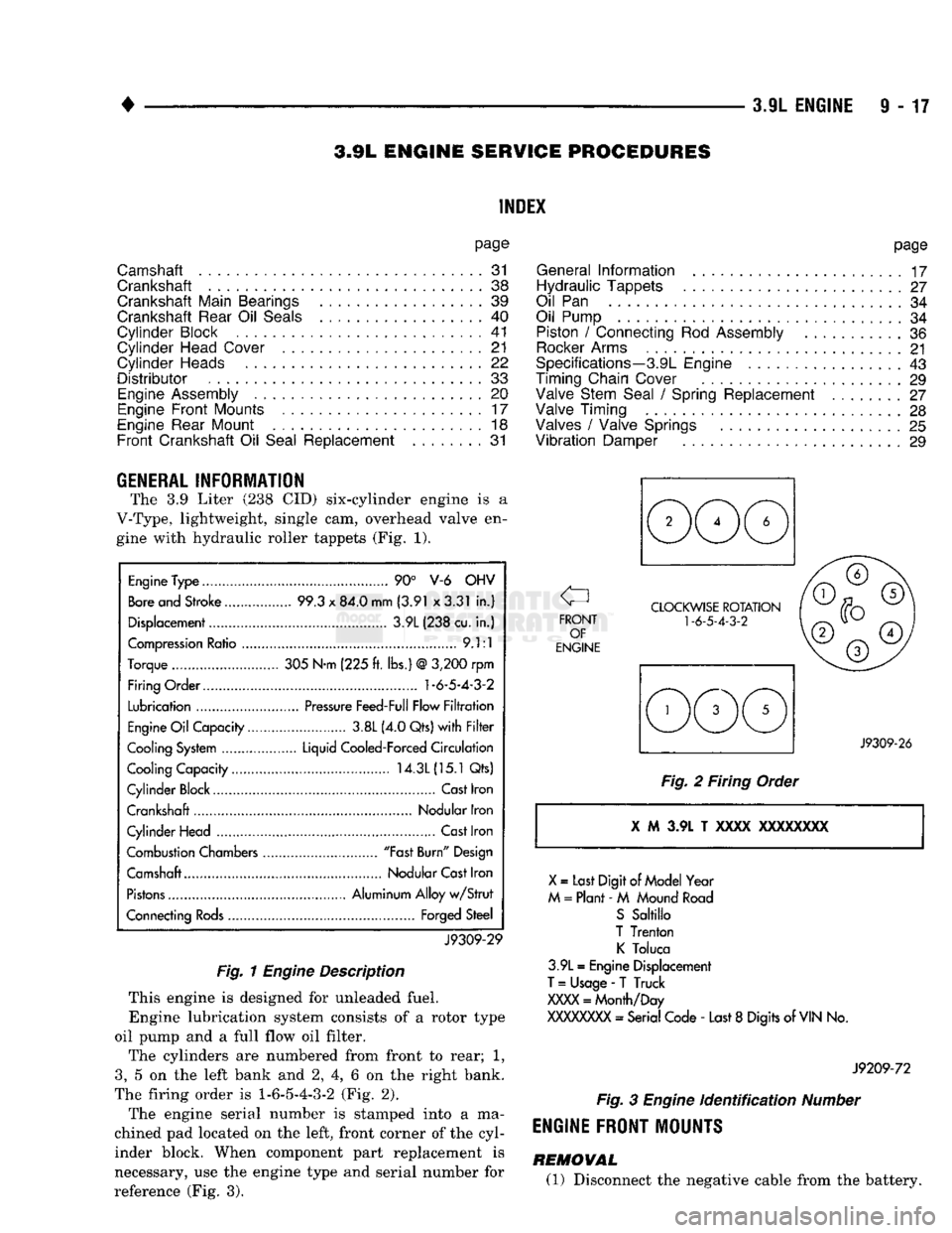
The 3.9 Liter (238 CID) six-cylinder engine is a
V-Type, lightweight, single cam, overhead valve en gine with hydraulic roller tappets (Fig. 1).
Engine
Type
90° V-6 OHV
Bore
and Stroke 99.3
x
84.0 mm (3.91 x3.31
in.)
Displacement 3.9L (238 cu.
in.)
Compression
Ratio
9.1:1
Torque 305 N-m (225
ft.
lbs.)
@
3,200
rpm
Firing Order.... 1-6-5-4-3-2
Lubrication
Pressure
Feed-Full Flow
Filtration
Engine
Oil
Capacity 3.8L (4.0 Qts)
with Filter
Cooling
System
Liquid Cooled-Forced
Circulation
Cooling Capacity 14.3L
(15.1
Qts)
Cylinder Block Cast Iron
Crankshaft Nodular Iron
Cylinder Head
Cast
Iron
Combustion Chambers "Fast
Burn"
Design
Camshaft Nodular
Cast
Iron
Pistons
Aluminum Alloy
w/Strut
Connecting
Rods
Forged Steel
J9309-29
Fig.
1
Engine
Description
This engine is designed for unleaded fuel. Engine lubrication system consists of a rotor type
oil pump and a full flow oil filter.
The cylinders are numbered from front to rear; 1,
3,
5 on the left bank and 2, 4, 6 on the right bank.
The firing order is
1-6-5-4-3-2
(Fig. 2).
The engine serial number is stamped into a ma
chined pad located on the left, front corner of the cyl
inder block. When component part replacement is
necessary, use the engine type and serial number for
reference (Fig. 3).
page
General
Information
17
Hydraulic Tappets
27
Oil
Pan 34
Oil Pump
34
Piston
/
Connecting
Rod
Assembly
36
Rocker
Arms
21
Specifications—3.9L Engine
43
Timing Chain Cover
29
Valve Stem Seal
/
Spring Replacement ........
27
Valve Timing
28
Valves
/
Valve Springs
25
Vibration
Damper
29
J9309-26
Fig.
2 Firing Order i M 3.9L T xxxx
XXXXXXXX
X
=
Last Digit
of
Model Year
M
=
Plant -
M
Mound
Road
S
Sabillo
T Trenton
K
Toluca
3.9L
=
Engine Displacement
T
=
Usage
-
T Truck
XXXX
=
Month/Day
XXXXXXXX
- Serial Code -
Last
8
Digits of
VIN
No.
J9209-72
Fig.
3
Engine
identification
Number
ENGINE FRONT MOUNTS
REMOVAL (1) Disconnect the negative cable from the battery.
Page 625 of 1502
TRANSFER
CASE
INSULATOR
MOUNTING PLATE
NUT(B
RAIL
ASSEMBLY
SPACER
UPPER
INSULATOR
NUT®
LOWER
INSULATOR
J9109-242
Fig.
9 Rear
Engine
Support—4WD
with
Manual
Transmission
(8) If necessary, remove the transmission support
spacer (automatic transmission) from the extension
assembly (Fig. 8).
(9) If necessary, remove the engine rear support
plate (automatic transmission) from the transfer case (Fig. 8).
INSTALLATION-4WD
(1) If removed, position the engine rear support
plate (automatic transmission) to the transfer case (Fig. 8). Install the bolts and tighten to 41 N-m (30
ft. lbs.) torque.
(2) If removed, position the transmission support
spacer (automatic transmission) to the extension as
sembly (Fig. 8). Install the bolts and tighten to 68 N-m (50 ft. lbs.) torque.
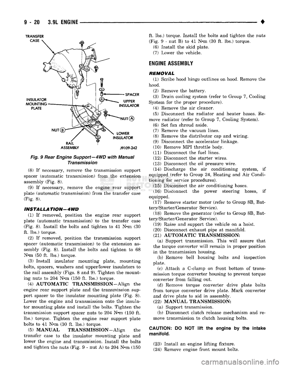
(3) Install insulator mounting plate, mounting
bolts,
spacers, washers and upper/lower insulators to
the rail assembly (Figs. 8 and 9). Tighten the mount
ing nuts to 204 N*m (150 ft. lbs.) torque.
(4) AUTOMATIC TRANSMISSION-Align the
engine rear support plate and the transmission sup
port spacer to the insulator mounting plate (Fig. 8). Lower the engine and transmission onto the insula
tor mounting plate and install the bolts. Tighten the transmission support spacer nuts to 204 N-m (150 ft. lbs.) torque. Tighten the engine rear support plate
bolts to 41 N-m (30 ft. lbs.) torque.
(5) MANUAL TRANSMISSION—Align the
transfer case to the insulator mounting plate and lower the engine and transmission. Install the bolts and tighten the nuts (Fig. 9 - nut A) to 204 N-m (150 ft. lbs.) torque. Install the bolts and tighten the nuts
(Fig. 9 - nut B) to 41 N-m (30 ft. lbs.) torque. (6) Install the skid plate.
(7) Lower the vehicle.
ENGINE
ASSEMBLY
REMOVAL (1) Scribe hood hinge outlines on hood. Remove the
hood.
(2) Remove the battery. (3) Drain cooling system (refer to Group 7, Cooling
System for the proper procedure).
(4) Remove the air cleaner. (5) Disconnect the radiator and heater hoses. Re
move radiator (refer to Group 7, Cooling System).
(6) Set fan shroud aside. (7) Remove the vacuum lines. (8) Remove the distributor cap and wiring.
(9) Disconnect the accelerator linkage.
(10) Remove MPI throttle body. (11) Disconnect the fuel lines. (12) Disconnect the starter wires.
(13) Disconnect the oil pressure wire. (14) Discharge the air conditioning system, if
equipped (refer to Group 24, Heating and Air Condi
tioning for service procedures). (15) Disconnect the air conditioning hoses.
(16) Disconnect the power steering hoses, if
equipped. (17) Remove starter motor (refer to Group 8B, Bat
tery/Starter/Generator Service). (18) Remove the generator (refer to Group 8B, Bat
tery/Starter/Generator Service).
(19) Raise and support the vehicle on a hoist.
(20) Disconnect exhaust pipe at manifold.
(21) AUTOMATIC TRANSMISSION: (a) Support transmission. This will assure that
the torque converter will remain in proper position in the transmission housing. (b) Remove bell housing bolts and inspection
plate.
(c) Attach a C-clamp on front bottom of trans
mission torque converter housing to prevent torque
converter from falling out.
(d) Remove torque converter drive plate bolts
from torque converter drive plate. Mark converter and drive plate to aid in assembly.
(22) MANUAL TRANSMISSION: (a) Support transmission.
(b) Disconnect clutch release mechanism and re
move transmission to clutch housing bolts.
CAUTION:
DO NOT
lift
the engine by the intake
manifold.
(23) Install an engine lifting fixture.
(24) Remove engine front mount bolts.
Page 626 of 1502
•
3.9L
ENGINE
9 - 21 (25) Lower the vehicle.
(26) On automatic transmission vehicles, discon
nect the engine from the torque converter drive
plate. On manual transmission vehicles, move engine forward until drive pinion shaft clears the clutch
disc.
Remove engine from engine compartment. (27) Install engine assembly on engine repair
stand.
INSTALLATION (1) Remove engine from the repair stand and posi
tion in the engine compartment.
(2) Install engine support fixture.
(3) Raise and support the vehicle on a hoist.
(4)
AUTOMATIC TRANSMISSION: (a) Position the torque converter and drive plate.
Install torque converter drive plate bolts. Tighten
the bolts to 31 Nnn (270 in. lbs.) torque.
(b) Install the engine front mounts.
(c) Install bell housing bolts. Tighten the bolts to
41 N-m (30 ft. lbs.) torque.
(d) Remove C-clamp.
(e) Install the inspection plate.
(5) MANUAL TRANSMISSION: (a) Position the drive pinion shaft to the clutch
disc.
(b) Connect the clutch release mechanism and
install the transmission to clutch bolts. Tighten the
bolts to 68 N-m (50 ft. lbs.) torque.
(c) Install the engine front mounts.
(6) Remove transmission support.
(7) Install exhaust pipe to manifold.
(8) Lower the vehicle.
(9) Remove engine lifting fixture.
(10) Install the generator (refer to Group 8B, Bat
tery/Starter/Generator Service). (11) Install starter motor (refer to Group 8B, Bat
tery/Starter/Generator Service). (12) Connect power steering hoses, if equipped.
(13) Connect air conditioning hoses.
(14) Evacuate and charge the air conditioning sys
tem, if equipped (refer to Group 24, Heater and Air Conditioning for service procedures). (15) Using a new gasket, install MPI throttle body.
Tighten the throttle body bolts to 23 N-m (200 in. lbs.) torque. (16) Connect the accelerator linkage.
(17) Connect the starter wires. (18) Connect the oil pressure wire.
(19) Install the distributor cap and wiring.
(20) Connect the vacuum lines.
(21) Connect the fuel lines.
(22) Install the radiator (refer to Group 7, Cooling
System). Connect the radiator hoses and heater
hoses.
(23) Install fan shroud in position. (24) Fill cooling system (refer to Group 7, Cooling
System for the proper procedures). (25) Install the air cleaner.
(26) Install the battery.
(27) Warm engine and adjust.
(28) Install hood and line up with the scribe
marks. (29) Road test vehicle.
CYLINDER
HEAD COVER
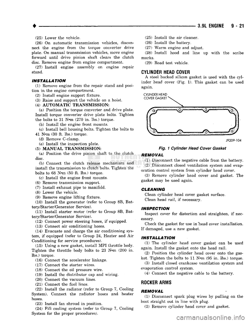
A steel backed silicon gasket is used with the cyl
inder head cover (Fig. 1). This gasket can be used again.
CYLINDER HEAD COVER GASKET
J9209-104
Fig.
1 Cylinder Head
Cover
Gasket
REMOVAL (1) Disconnect the negative cable from the battery.
(2) Disconnect closed ventilation system and evap
oration control system from cylinder head cover. (3) Remove cylinder head cover and gasket. The
gasket may be used again.
CLEANING Clean cylinder head cover gasket surface. Clean head rail, if necessary.
INSPECTION Inspect cover for distortion and straighten, if nec
essary. Check the gasket for use in "head cover installation.
If damaged, use a new gasket.
INSTALLATION (1) The cylinder head cover gasket can be used
again. Install the gasket onto the head rail.
(2) Position the cylinder head cover onto the gas
ket. Tighten the bolts to 11 N-m (95 in. lbs.) torque. (3) Install closed crankcase ventilation system and
evaporation control system.
(4) Connect the negative cable to the battery.
ROCKER
ARMS
REMOVAL (1) Disconnect spark plug wires by pulling on the
boot straight out in line with plug.
(2) Remove cylinder head cover and gasket.
Page 627 of 1502
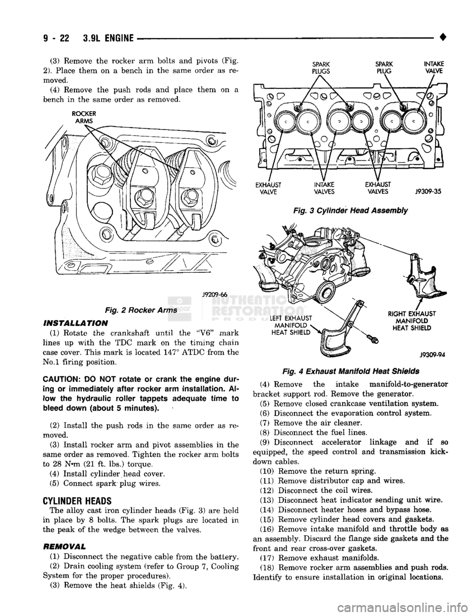
(3) Remove the rocker arm bolts and pivots (Fig.
2).
Place them on a bench in the same order as re
moved.
(4) Remove the push rods and place them on a
bench in the same order as removed.
ROCKER
ARMS
J9209-66
Fig.
2
Rocker Arms
INSTALLATION
(1) Rotate the crankshaft until the "V6" mark
lines up with the TDC mark on the timing chain
case cover. This mark is located 147° ATDC from the
No.l firing position.
CAUTION:
DO NOT
rotate
or
crank
the
engine dur
ing
or
immediately
after
rocker
arm
installation.
Al
low
the
hydraulic roller tappets adequate time
to
bleed down (about
5
minutes).
(2) Install the push rods in the same order as re
moved.
(3) Install rocker arm and pivot assemblies in the
same order as removed. Tighten the rocker arm bolts
to 28 N*m (21 ft. lbs.) torque.
(4) Install cylinder head cover.
(5) Connect spark plug wires.
CYLINDER
HEADS
The alloy cast iron cylinder heads (Fig. 3) are held
in place by 8 bolts. The spark plugs are located in
the peak of the wedge between the valves.
REMOVAL
(1) Disconnect the negative cable from the battery.
(2) Drain cooling system (refer to Group 7, Cooling
System for the proper procedures). (3) Remove the heat shields (Fig. 4).
SPARK SPARK
INTAKE
PLUGS
PLUG VALVE
EXHAUST INTAKE EXHAUST VALVE VALVES VALVES
J9309-35
Fig.
3 Cylinder Head
Assembly Fig.
4
Exhaust
Manifold Heat
Shields
(4) Remove the intake manifold-to-generator
bracket support rod. Remove the generator.
(5) Remove closed crankcase ventilation system.
(6) Disconnect the evaporation control system.
(7) Remove the air cleaner.
(8) Disconnect the fuel lines.
(9) Disconnect accelerator linkage and if so
equipped, the speed control and transmission kick-
down cables. (10) Remove the return spring.
(11) Remove distributor cap and wires.
(12) Disconnect the coil wires.
(13) Disconnect heat indicator sending unit wire.
(14) Disconnect heater hoses and bypass hose.
(15) Remove cylinder head covers and gaskets.
(16) Remove intake manifold and throttle body as
an assembly. Discard the flange side gaskets and the
front and rear cross-over gaskets.
(17) Remove exhaust manifolds.
(18) Remove rocker arm assemblies and push rods.
Identify to ensure installation in original locations.
Page 629 of 1502
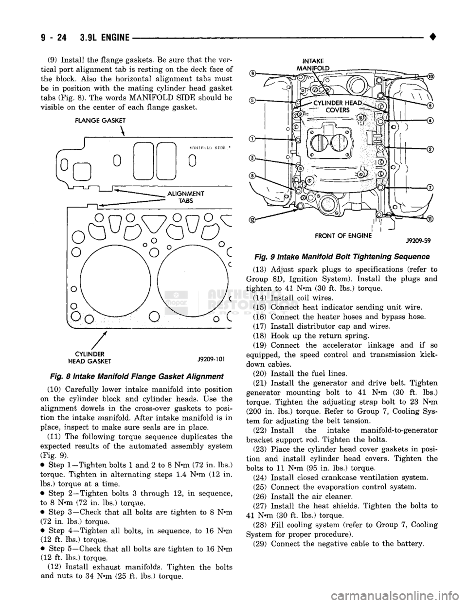
(9) Install the flange gaskets. Be sure that the ver
tical port alignment tab is resting on the deck face of
the block. Also the horizontal alignment tabs must
be in position with the mating cylinder head gasket
tabs (Fig. 8). The words MANIFOLD SIDE should be
visible on the center of each flange gasket.
FLANGE GASKET
INTAKE
AAANIFOLD
CYLINDER
HEAD GASKET
J9209-101
Fig.
8 Intake Manifold Flange
Gasket
Alignment
(10) Carefully lower intake manifold into position
on the cylinder block and cylinder heads. Use the alignment dowels in the cross-over gaskets to posi
tion the intake manifold. After intake manifold is in
place, inspect to make sure seals are in place.
(11) The following torque sequence duplicates the
expected results of the automated assembly system
(Fig. 9).
• Step
1-Tighten
bolts 1 and 2 to 8 N-m (72 in. lbs.)
torque. Tighten in alternating steps 1.4 N-m (12 in. lbs.) torque at a time.
• Step 2—Tighten bolts 3 through 12, in sequence,
to 8 N-m (72 in. lbs.) torque.
• Step 3—Check that all bolts are tighten to 8 N-m (72 in. lbs.) torque.
• Step 4—Tighten all bolts, in sequence, to 16 N-m (12 ft. lbs.) torque.
• Step 5—Check that all bolts are tighten to 16 N-m (12 ft. lbs.) torque. (12) Install exhaust manifolds. Tighten the bolts
and nuts to 34 N-m (25 ft. lbs.) torque.
FRONT OF ENGINE
J9209-59
Fig.
9 Intake Manifold
Bolt
Tightening
Sequence
(13) Adjust spark plugs to specifications (refer to
Group 8D, Ignition System). Install the plugs and
tighten to 41 N-m (30 ft. lbs.) torque.
(14) Install coil wires. (15) Connect heat indicator sending unit wire.
(16) Connect the heater hoses and bypass hose.
(17) Install distributor cap and wires.
(18) Hook up the return spring.
(19) Connect the accelerator linkage and if so
equipped, the speed control and transmission kick-
down cables.
(20) Install the fuel lines.
(21) Install the generator and drive belt. Tighten
generator mounting bolt to 41 N-m (30 ft. lbs.)
torque. Tighten the adjusting strap bolt to 23 N-m (200 in. lbs.) torque. Refer to Group 7, Cooling Sys
tem for adjusting the belt tension. (22) Install the intake manifold-to-generator
bracket support rod. Tighten the bolts. (23) Place the cylinder head cover gaskets in posi
tion and install cylinder head covers. Tighten the
bolts to 11 N-m (95 in. lbs.) torque.
(24) Install closed crankcase ventilation system.
(25) Connect the evaporation control system.
(26) Install the air cleaner.
(27) Install the heat shields. Tighten the bolts to
41 N-m (30 ft. lbs.) torque. (28) Fill cooling system (refer to Group 7, Cooling
System for proper procedure). (29) Connect the negative cable to the battery.
Page 634 of 1502
•
3.9L
ENGINE
I - 21
VIBRATION
DAMPER
REMOVAL
(1) Disconnect the negative cable from the battery,
(2) Remove fan shroud retainer bolts and set
shroud back over engine.
(3) Remove the cooling system fan.
(4) Remove the serpentine belt (refer to Group 7,
Cooling System).
(5) Remove the vibration damper pulley.
(6) Remove vibration damper bolt and washer from
end of crankshaft.
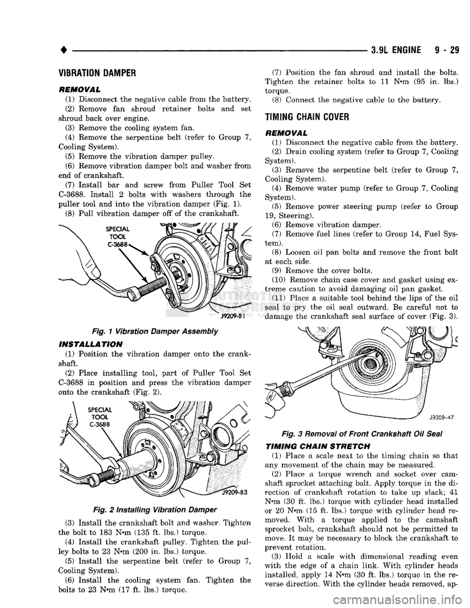
(7) Install bar and screw from Puller Tool Set
C-3688.
Install 2 bolts with washers through the
puller tool and into the vibration damper (Fig. 1).
(8) Pull vibration damper off of the crankshaft.
J9209-81
Fig. 1 Vibration
Damper
Assembly INSTALLATION
(1) Position the vibration damper onto the crank
shaft.
(2) Place installing tool, part of Puller Tool Set
C-3688 in position and press the vibration damper
onto the crankshaft (Fig. 2).
Fig. 2 Installing Vibration Damper
(3) Install the crankshaft bolt and washer. Tighten
the bolt to 183 N*m (135 ft. lbs.) torque.
(4) Install the crankshaft pulley. Tighten the pul
ley bolts to 23 N*m (200 in. lbs.) torque.
(5) Install the serpentine belt (refer to Group 7,
Cooling System).
(6) Install the cooling system fan. Tighten the
bolts to 23 N*m (17 ft. lbs.) torque. (7) Position the fan shroud and install the bolts.
Tighten the retainer bolts to 11 N*m (95 in. lbs.)
torque.
(3)
Connect the negative cable to the battery.
TIMING CHAIN
COVER
REMOVAL (1)
Disconnect the negative cable from the battery.
(2)
Drain cooling system (refer to Group 7, Cooling
System).
(3)
Remove the serpentine belt (refer to Group 7,
Cooling System).
(4)
Remove water pump (refer to Group 7, Cooling
System).
(5)
Remove power steering pump (refer to Group
19,
Steering).
(6)
Remove vibration damper. (7) Remove fuel lines (refer to Group 14, Fuel Sys
tem).
(8) Loosen oil pan bolts and remove the front bolt
at each side.
(9)
Remove the cover bolts.
(10)
Remove chain case cover and gasket using ex
treme caution to avoid damaging oil pan gasket.
(11)
Place a suitable tool behind the lips of the oil
seal to pry the oil seal outward. Be careful not to
damage the crankshaft seal surface of cover (Fig. 3). Fig. 3 Removal of Front Crankshaft Oil Seal
TIMING CHAIN STRETCH
(1) Place a scale next to the timing chain so that
any movement of the chain may be measured.
(2)
Place a torque wrench and socket over cam
shaft sprocket attaching bolt. Apply torque in the di
rection of crankshaft rotation to take up slack; 41
N#m (30 ft. lbs.) torque with cylinder head installed or 20 N»m (15 ft. lbs.) torque with cylinder head re
moved. With a torque applied to the camshaft sprocket bolt, crankshaft should not be permitted to
move. It may be necessary to block the crankshaft to
prevent rotation.
(3)
Hold a scale with dimensional reading even
with the edge of a chain link. With cylinder heads installed, apply 14 N*m (30 ft. lbs.) torque in the re
verse direction. With the cylinder heads removed, ap-
Page 636 of 1502
•
3.9L
ENGINE
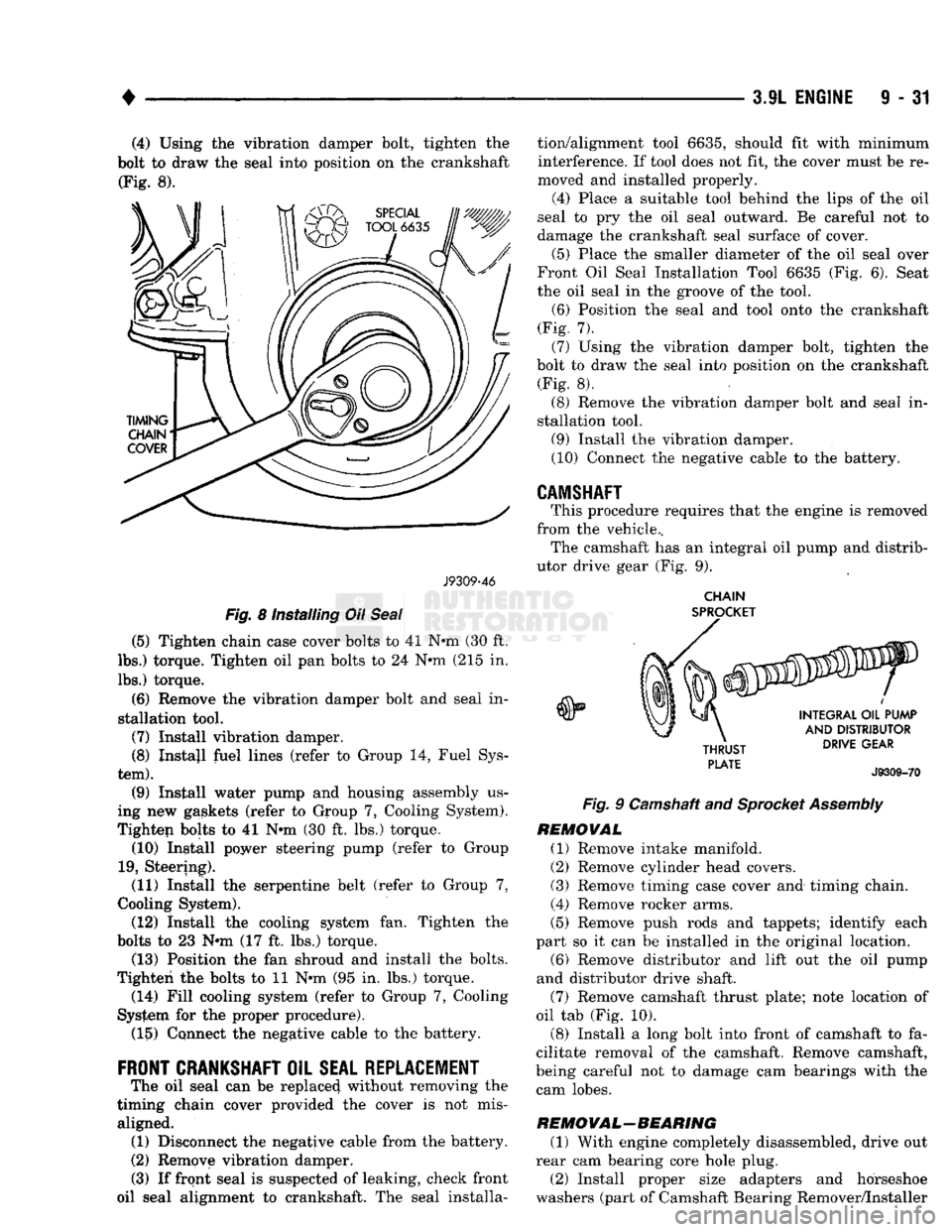
9 - 31 (4) Using the vibration damper bolt, tighten the
bolt to draw the seal into position on the crankshaft (Fig. 8).
J9309-46
Fig.
8 installing Oil
Seal
(5) Tighten chain case cover bolts to 41 N-m (30 ft.
lbs.) torque. Tighten oil pan bolts to 24 N*m (215 in.
lbs.) torque.
(6) Remove the vibration damper bolt and seal in
stallation tool.
(7) Install vibration damper. (8) Instajl fuel lines (refer to Group 14, Fuel Sys
tem).
(9) Install water pump and housing assembly us
ing new gaskets (refer to Group 7, Cooling System).
Tighten bolts to 41 N-m (30 ft. lbs.) torque. (10) Install power steering pump (refer to Group
19,
Steering). (11) Install the serpentine belt (refer to Group 7,
Cooling System). (12) Install the cooling system fan. Tighten the
bolts to 23 N-m (17 ft. lbs.) torque. (13) Position the fan shroud and install the bolts.
Tighten the bolts to 11 N-m (95 in. lbs.) torque. (14) Fill cooling system (refer to Group 7, Cooling
System for the proper procedure). (15) Connect the negative cable to the battery.
FRONT
CRANKSHAFT
OIL
SEAL REPLACEMENT
The oil seal can be replaced without removing the
timing chain cover provided the cover is not mis aligned. (1) Disconnect the negative cable from the battery.
(2) Remove vibration damper.
(3) If front seal is suspected of leaking, check front
oil seal alignment to crankshaft. The seal installa tion/alignment tool 6635, should fit with minimum
interference. If tool does not fit, the cover must be re
moved and installed properly.
(4)
Place a suitable tool behind the lips of the oil
seal to pry the oil seal outward. Be careful not to
damage the crankshaft seal surface of cover.
(5) Place the smaller diameter of the oil seal over
Front Oil Seal Installation Tool 6635 (Fig. 6). Seat
the oil seal in the groove of the tool.
(6) Position the seal and tool onto the crankshaft
(Fig. 7). (7) Using the vibration damper bolt, tighten the
bolt to draw the seal into position on the crankshaft (Fig. 8).
(8) Remove the vibration damper bolt and seal in
stallation tool. (9) Install the vibration damper.
(10) Connect the negative cable to the battery.
CAMSHAFT
This procedure requires that the engine is removed
from the vehicle.. The camshaft has an integral oil pump and distrib
utor drive gear (Fig. 9).
CHAIN
SPROCKET
Fig.
9 Camshaft and
Sprocket
Assembly
REMOVAL
(1) Remove intake manifold.
(2) Remove cylinder head covers. (3) Remove timing case cover and timing chain.
(4) Remove rocker arms.
(5) Remove push rods and tappets; identify each
part so it can be installed in the original location. (6) Remove distributor and lift out the oil pump
and distributor drive shaft.
(7) Remove camshaft thrust plate; note location of
oil tab (Fig. 10).
(8) Install a long bolt into front of camshaft to fa
cilitate removal of the camshaft. Remove camshaft,
being careful not to damage cam bearings with the cam lobes.
RE
MO
VAL-BEA RING
(1) With engine completely disassembled, drive out
rear cam bearing core hole plug.
(2) Install proper size adapters and horseshoe
washers (part of Camshaft Bearing Remover/Installer
Page 647 of 1502
(2) Insert a 3.175 mm (1/8 inch) finish wire or
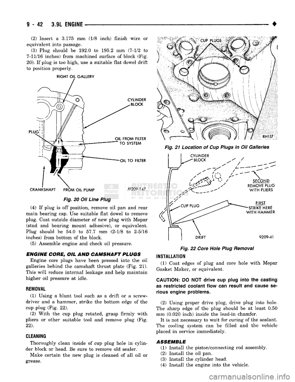
equivalent into passage.
(3) Plug should be 192.0 to 195.2 mm (7-1/2 to
7-11/16 inches) from machined surface of block (Fig.
20).
If plug is too high, use a suitable flat dowel drift
to position properly.
RIGHT
OIL
GALLERY
CYLINDER
BLOCK
PLUG
OIL
FROM
FILTER
TO
SYSTEM
OIL
TO
FILTER
CRANKSHAFT
FROM
OIL
PUMP
J9209-147
Fig.
20 Oil
Line
Plug
(4) If plug is off position, remove oil pan and rear
main bearing cap. Use suitable flat dowel to remove
plug. Coat outside diameter of new plug with Mopar (stud and bearing mount adhesive), or equivalent.
Plug should be 54.0 to 57.7 mm (2-1/8 to 2-5/16 inches) from bottom of the block.
(5) Assemble engine and check oil pressure.
ENGINE
CORE,
OIL AND
CAMSHAFT
PLUGS
Engine core plugs have been pressed into the oil
galleries behind the camshaft thrust plate (Fig. 21).
This will reduce internal leakage and help maintain
higher oil pressure at idle.
REMOWAL
(1) Using a blunt tool such as a drift or a screw
driver and a hammer, strike the bottom edge of the
cup plug (Fig. 22).
(2) With the cup plug rotated, grasp firmly with
pliers or other suitable tool and remove plug (Fig.
22).
CLEANING
* Thoroughly clean inside of cup plug hole in cylin
der block or head. Be sure to remove old sealer.
Make certain the new plug is cleaned of all oil or
grease. RH157
Fig.
21 Location of Cup
Plugs
in Oil Galleries Jr
CYLINDER
^
BLOCK
/
SECOND
REMOVE
PLUG
WITH
PLIERS
FIRST
STRIKE
HERE
WITH
HAMMER
DRIFT
9209-41
Fig.
22
Core
Hole
Plug
Removal
INSTALLATION
(1) Coat edges of plug and core hole with Mopar
Gasket Maker, or equivalent.
CAUTION:
DO NOT drive cup
plug
into the
casting
as
restricted
coolant
flow can result and
cause
se
rious
engine
problems.
(2) Using proper drive plug, drive plug into hole.
The sharp edge of the plug should be at least 0.50 mm (0.020 inch) inside the lead-in chamfer. It is not necessary to wait for curing of the sealant.
The cooling system can be filled and the vehicle
placed in service immediately.
ASSEMBLE
(1) Install the piston/connecting rod assembly.
(2) Install the oil pan.
(3) Install the cylinder head.
(4) Install the engine into the vehicle.