Page 1149 of 1640
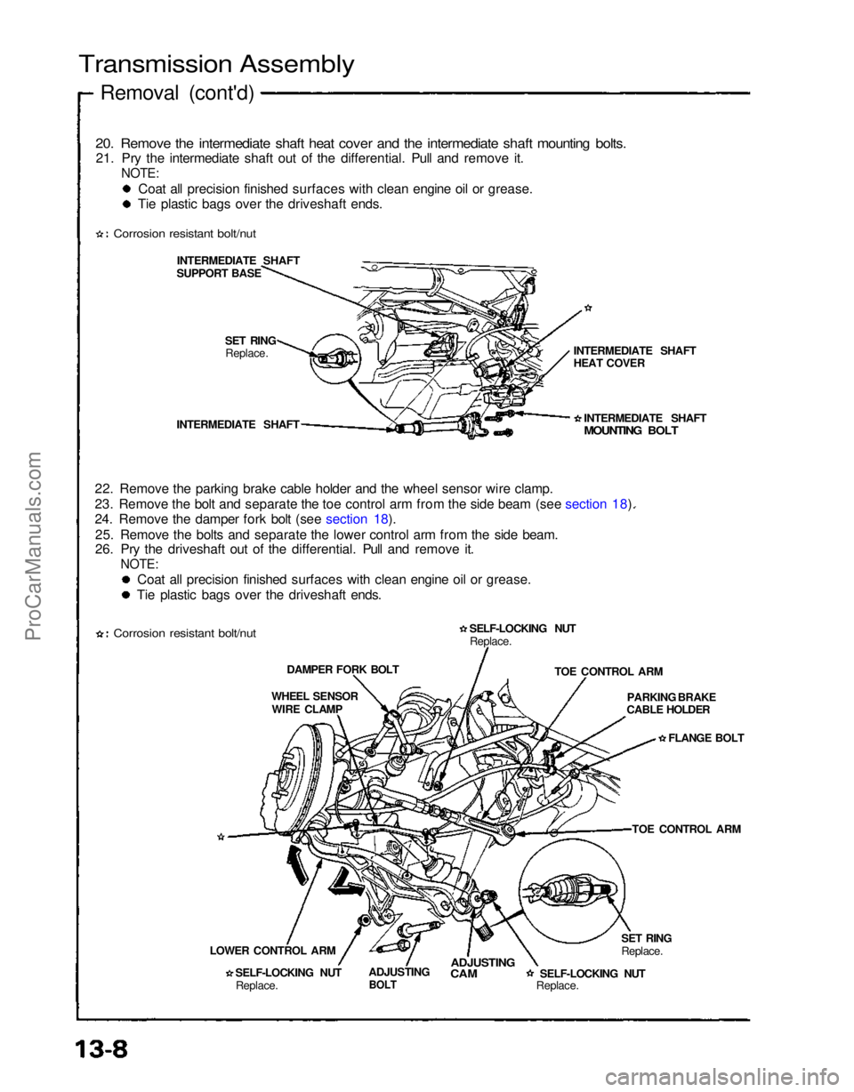
12. Remove the parking brake cable holders from the rear beam rod.
13. Remove the rear beam rod.
14. Remove the front exhaust pipe A.
Corrosion resistant bolt/nut
EXHAUST
PIPE ASELF-LOCKING NUT
Replace.
GASKET
Replace.
GASKET
Replace.
REAR BEAM ROD
1 5. Remove the parking brake cable holder and the wheel sensor wire clamp. 16. Remove the bolt and separate the toe control arm from the side beam (see section 18).
17. Remove the damper fork bolt (see section 18). 18. Remove the bolts and separate the lower control arm from the side beam (see section 18).
19. Pry the driveshaft out of the differential. Pull and remove it. SELF-LOCKING NUT
Replace.
PARKING BRAKE
CABLE HOLDERS
PARKING BRAKE
CABLE HOLDER
FLANGE BOLT
SIDE BEAM TOE CONTROL ARM
SELF-LOCKING NUT Replace. SELF-LOCKING NUT
Replace.
WHEEL SENSOR
WIRE CLAMP
DAMPER FORK BOLT
ADJUSTING
CAM
DRIVESHAFT
ADJUSTING BOLT SELF-LOCKING NUT
Replace.
LOWER CONTROL
ARM
(cont'd)
Corrosion resistant bolt/nutProCarManuals.com
Page 1150 of 1640

Transmission Assembly
Removal (cont'd)
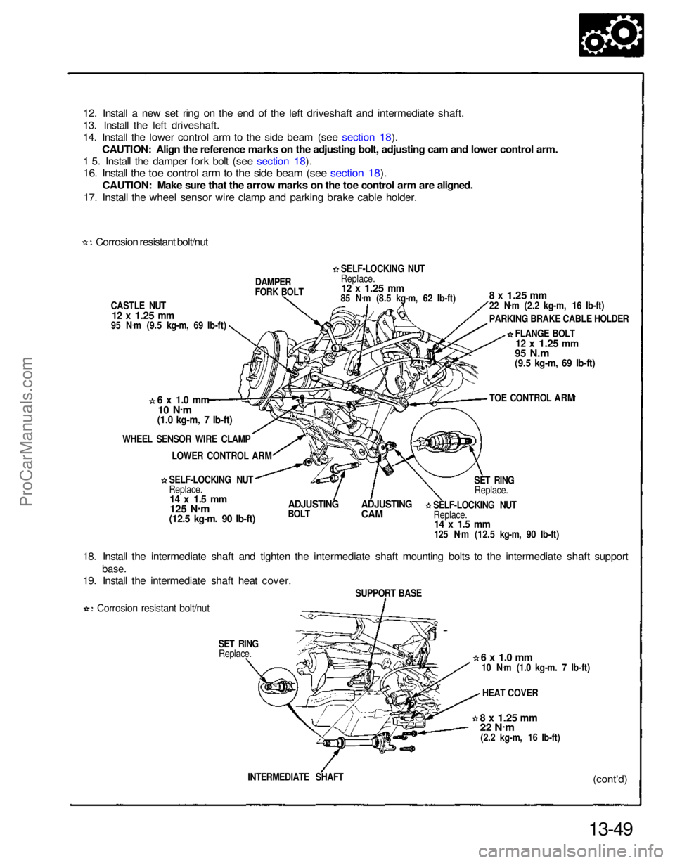
20. Remove the intermediate shaft heat cover and the intermediate shaft mounting bolts.
21. Pry the intermediate shaft out of the differential. Pull and remove it.
NOTE:
Coat all precision finished surfaces with clean engine oil or grease.
Tie plastic bags over the driveshaft ends.
Corrosion resistant bolt/nut
INTERMEDIATE SHAFT
SUPPORT BASE
SET RINGReplace.
INTERMEDIATE SHAFT
22. Remove the parking brake cable holder and the wheel sensor wire clamp.
23. Remove the bolt and separate the toe control arm from the side beam (see section 18).
24. Remove the damper fork bolt (see section 18). 25. Remove the bolts and separate the lower control arm from the side beam.
26. Pry the driveshaft out of the differential. Pull and remove it.
NOTE:
Coat all precision finished surfaces with clean engine oil or grease.
Tie plastic bags over the driveshaft ends.
Corrosion resistant bolt/nut
DAMPER FORK BOLT
WHEEL SENSOR WIRE CLAMP
LOWER CONTROL ARM SELF-LOCKING NUTReplace. ADJUSTING
BOLT
ADJUSTING
CAM
SELF-LOCKING NUT
Replace.SET RING
Replace.TOE CONTROL ARM
PARKING BRAKE
CABLE HOLDER
FLANGE BOLT
TOE CONTROL ARM
SELF-LOCKING NUT
Replace. INTERMEDIATE SHAFT
MOUNTING BOLT
INTERMEDIATE SHAFT
HEAT COVERProCarManuals.com
Page 1161 of 1640

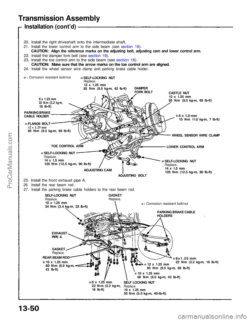
12. Install a new set ring on the end of the left driveshaft and intermediate shaft.
13. Install the left driveshaft.
14. Install the lower control arm to the side beam (see section 18).
CAUTION: Align the reference marks on the adjusting bolt, adjusting cam and lower control arm.
1 5. Install the damper fork bolt (see section 18).
16. Install the toe control arm to the side beam (see section 18).
CAUTION: Make sure that the arrow marks on the toe control arm are aligned.
17. Install the wheel sensor wire clamp and parking brake cable holder.
Corrosion resistant bolt/nut
CASTLE NUT
12 x
1.25
mm
95 N .
m (9.5 kg-m, 69 Ib-ft) DAMPER
FORK BOLT
6 x 1.0 mm
10 N .
m
(1.0 kg-m, 7 Ib-ft)
WHEEL SENSOR WIRE CLAMP LOWER CONTROL ARM
SELF-LOCKING NUT
Replace.
14 x 1.5 mm
125 N .
m
(12.5 kg-m. 90 Ib-ft)
ADJUSTING
BOLT
ADJUSTING
CAM
18. Install the intermediate shaft and tighten the intermediate shaft mounting bolts to the intermediate shaft support
base.
19. Install the intermediate shaft heat cover.
Corrosion resistant bolt/nut
SET RINGReplace.
13-49(cont'd)
INTERMEDIATE SHAFT
8 x
1.25
mm
22 N
.
m
(2.2 kg-m, 16 Ib-ft) HEAT COVER
6 x 1.0 mm
10 N .
m (1.0 kg-m. 7 Ib-ft)
SUPPORT BASE SELF-LOCKING NUT
Replace.
14 x 1.5 mm
125 N .
m (12.5 kg-m, 90 Ib-ft) SET RING
Replace. TOE CONTROL ARM
FLANGE BOLT
12 x
1.25
mm
95 N.m
(9.5 kg-m, 69 Ib-ft)
8 x
1.25
mm
22 N
.
m (2.2 kg-m, 16 Ib-ft)
PARKING BRAKE CABLE HOLDER
SELF-LOCKING NUT
Replace.
12 x
1.25
mm
85 N .
m (8.5 kg-m, 62 Ib-ft)ProCarManuals.com
Page 1162 of 1640

Transmission Assembly
Installation (cont'd)
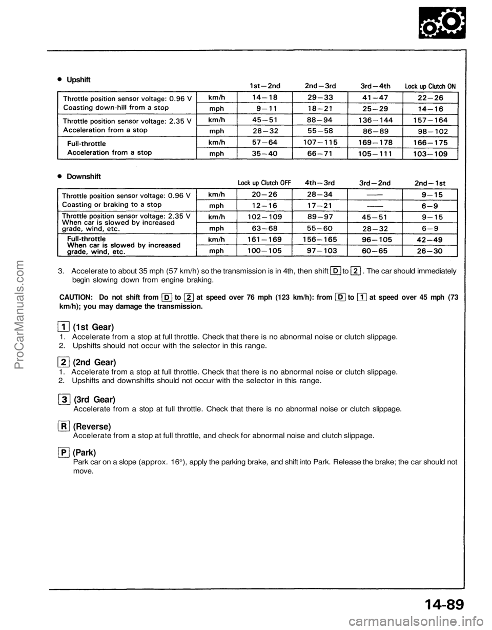
20. Install the right driveshaft onto the intermediate shaft.
21. Install the lower control arm to the side beam (see section 18). CAUTION: Align the reference marks on the adjusting bolt, adjusting cam and lower control arm.
22. Install the damper fork bolt (see section 18).
23. Install the toe control arm to the side beam (see section 18).
CAUTION: Make sure that the arrow marks on the toe control arm are aligned.
24. Install the wheel sensor wire clamp and parking brake cable holder.
Corrosion resistant bolt/nut
SELF-LOCKING NUT
Replace.
12 x
1.25
mm
85 N .
m (8.5 kg-m, 62 Ib-ft)
8 x
1.25
mm
22 N.m
(2.2
kg-m,
16 Ib-ft)
PARKING BRAKE
CABLE HOLDER
FLANGE BOLT
12 x
1.25
mm
95 N .
m (9.5 kg-m, 69 Ib-ft)
TOE CONTROL ARM
SELF-LOCKING NUT Replace.
14 x 1.5 mm
125 N.m (12.5 kg-m, 90 Ib-ft)
ADJUSTING CAM
25. Install the front exhaust pipe A.
26. Install the rear beam rod. 27. Install the parking brake cable holders to the rear beam rod. ADJUSTING BOLT
SELF-LOCKING NUT Replace.
10 x
1.25
mm
34 N .
m (3.4 kg-m, 25 Ib-ft)
GASKET
Replace.
Corrosion resistant bolt/nut
SELF-LOCKING NUT
Replace.
14 x 1.5 mm
125 N .
m (12.5 kg-m, 90 Ib-ft)
LOWER CONTROL ARM
WHEEL SENSOR WIRE CLAMP
6 x 1.0 mm
10 N .
m 11.0 kg-m, 7 Ib-ft)
CASTLE NUT
12 x
1.25
mm
95 N .
m (9.5 kg-m, 69 Ib-ft)
DAMPER
FORK BOLT
EXHAUST
PIPE A
GASKET
Replace.
REAR BEAM ROD
10 x
1.25
mm
60 N .
m
(6.0 kg-m,
43 Ib-ft)
8 x
1.25
mm
22 N.
m
(2.2 kg-m,
16 Ib-ft) SELF LOCKING NUT
Replace.
10 x
1.25
mm
55 N .
m (5.5 kg-m, 40-lb-ft)
10 x
1.25
mm
60 N .
m (6.0 kg-m, 43 Ib-ft) 95 N
.
m (9.5 kg-m, 69 Ib-ft)
12 x
1.25
mm
8x1.25 mm
22 N .
m (2.2 kg-m, 16 Ib-ft)
PARKING BRAKE CABLE
HOLDERSProCarManuals.com
Page 1178 of 1640
Description
Electronic Control System (cont'd)
TRANSMISSION CONTROL MODULE (TCM)
ENGINE
CONTROL
MODULE
(ECM) Shift Control
Lock-up
Control
TCS Control Unit
EPS Control Unit Engine RPM
Air Conditioning Signal Brake Switch Signal
Vehicle Speed Sensor Signal
Mainshaft Speed Sensor Signal
Countershaft Speed Sensor Signal
Self-Diagnosis
Function
Self-Diagnosis Indicator
INTERLOCK
CONTROL UNIT
Lock-up Control Solenoid
Valve B
Lock-up Control Solenoid
Valve A Shift Control Solenoid
Valve B
Shift Control Solenoid
Valve A
Linear Solenoid
Throttle Position
Sensor Signal
Engine Coolant
Temperature
Sensor Signal
Accet Pedal
Angle Signal
Service Check
Connector
ProCarManuals.com
Page 1221 of 1640
Road Test
NOTE:
Warm up the engine to normal operating temperature (the cooling fan comes on).
When the engine coolant temperature is below normal operating temperature, the shift point is higher than specifiedvehicle speed.
Range 1. Apply parking brake and block the wheels. Start the engine, then move the selector to while depressing the brake
pedal. Depress the accelerator pedal, and release it suddenly. Engine should not stall.
2. Check that shift points occur at approximate speeds shown. Also check for abnormal noise and clutch slippage.
NOTE: Throttle position sensor voltage represents the throttle opening.
DIGITAL MULTIMETER
KS–AHM–32–003
ECM
TEST HARNESS
07LAJ–PT3010A
1. Connect the Test Harness between the ECM and connector (see section 11).
2. Set the digital multimeter to check voltage between D11 (+) terminal and D22 (-) terminal for the throttle posi- tion sensor.ProCarManuals.com
Page 1222 of 1640

Upshift
Downshift
3. Accelerate to about 35 mph (57 km/h) so the transmission is in 4th, then shift to . The car should immediately
begin slowing down from engine braking.
CAUTION: Do not shift from to at speed over 76 mph (123 km/h): from to at speed over 45 mph (73
km/h); you may damage the transmission.
(1st Gear)
1. Accelerate from a stop at full throttle. Check that there is no abnormal noise or clutch slippage.
2. Upshifts should not occur with the selector in this range.
(2nd Gear)
1. Accelerate from a stop at full throttle. Check that there is no abnormal noise or clutch slippage.
2. Upshifts and downshifts should not occur with the selector in this range.
(3rd Gear)
Accelerate from a stop at full throttle. Check that there is no abnormal noise or clutch slippage.
(Reverse)
Accelerate from a stop at full throttle, and check for abnormal noise and clutch slippage.
(Park)
Park car on a slope (approx. 16°), apply the parking brake, and shift into Park. Release the brake; the car should not
move.ProCarManuals.com
Page 1223 of 1640
Stall Speed
Test
CAUTION:
To prevent transmission damage, do not test stall speed for more than 10 seconds at a time.
Do not shift the lever while raising the engine speed.
Be sure to remove the pressure gauge before testing stall speed.
1. Engage the parking brake and block all four wheels.
2. Connect the tachometer, and start the engine.
3. Make sure the A/C switch is OFF.
4. After the engine has warmed up to normal operating temperature (the cooling fan comes on), shift into position.
5. Fully depress the brake pedal and accelerator for 6 to 8 seconds, and note engine speed.
6. Allow 2 minutes for cooling, then repeat same test in and position.
NOTE:
Stall speed tests should be used for diagnostic pressure only.
Stall speed should be the same in and
Stall Speed RPM: Specification:
1,950-2,250
rpmProCarManuals.com