Page 622 of 1640
Trunk Li d
Replacement/Adjustmen t
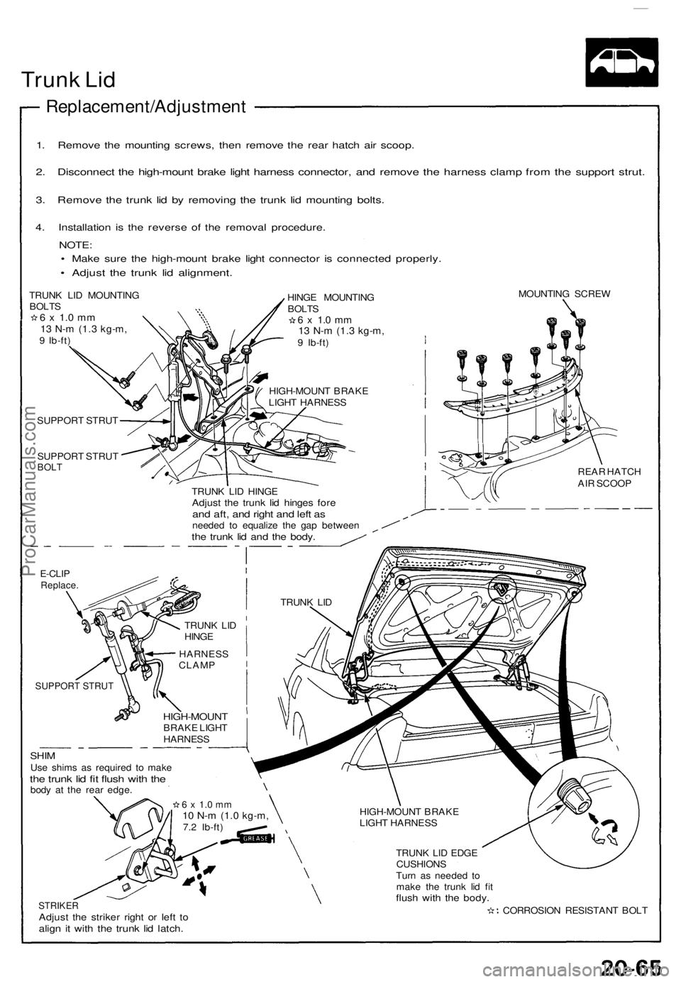
1. Remov e th e mountin g screws , the n remov e th e rea r hatc h ai r scoop .
2. Disconnec t th e high-moun t brak e ligh t harnes s connector , an d remov e th e harnes s clam p fro m th e suppor t strut .
3. Remov e th e trun k li d b y removin g th e trun k li d mountin g bolts .
4. Installatio n i s th e revers e of the remova l procedure .
NOTE:
• Mak e sur e th e high-moun t brak e ligh t connecto r i s connecte d properly .
• Adjus t th e trun k li d alignment .
TRUNK LI D MOUNTIN GBOLTS6 x 1. 0 m m13 N- m (1. 3 kg-m ,9 Ib-ft ) HING
E MOUNTIN G
BOLT S
6 x 1. 0 m m13 N- m (1. 3 kg-m ,9 Ib-ft )
HIGH-MOUN T BRAK E
LIGH T HARNES S MOUNTIN
G SCRE W
SUPPOR T STRU T
SUPPOR T STRU T
BOLT
TRUN K LI D HING EAdjust th e trun k li d hinge s for eand aft , an d righ t an d lef t a sneede d t o equaliz e th e ga p betwee nthe trun k li d an d th e body .
REAR HATC H
AI R SCOO P
E-CLIPReplace .
HARNES S
CLAM P
SUPPORT STRUT
SHIMUse shim s a s require d t o mak ethe trun k li d fi t flus h wit h th ebod y a t th e rea r edge .
HIGH-MOUN TBRAKE LIGH THARNES S
STRIKERAdjust th e strike r righ t o r lef t t oalig n i t wit h th e trun k li d latch .
HIGH-MOUN T BRAK E
LIGH T HARNES S
TRUN K LI D EDG E
CUSHION S
Tur n a s neede d t o
mak e th e trun k li d fi t
flus h wit h th e body .
CORROSIO N RESISTAN T BOL T
6 x 1. 0 m m10 N- m (1. 0 kg-m ,7.2 Ib-ft ) TRUN
K LI D
TRUN K LI D
HING E
ProCarManuals.com
Page 789 of 1640
Gauge Assembly
Bulb Locations
GAUGE LIGHTS (1.4W x 2)
SRS INDICATOR LIGHT (1.4 W)
RIGHT TURN SIGNAL INDICATOR LIGHT (1.4 W)
EPS INDICATOR LIGHT (1.4 W)
BRAKE SYSTEM LIGHT (1.4 W)
SEAT BELT REMINDER LIGHT (1.4 W)
TCS INDICATOR
LIGHT (1.96 W)
LOW FUEL INDICATOR
LIGHT (1.4 W)
GAUGE LIGHT
(1.4
W)
HIGH BEAM INDICATOR LIGHT (1.4 W)
LEFT TURN SIGNAL INDICATOR LIGHT (1.4 W)
ABS
INDICATOR LIGHT (1.4 W)
CHARGING SYSTEM LIGHT (1.4 W)
MALFUNCTION
INDICATOR
LAMP (MIL)
(1.4W)
LOW OIL PRESSURE
INDICATOR
LIGHT (1.4 W)
GAUGE LIGHT
(1.4
W)
GAUGE LIGHT
(3.0
W)
GAUGE LIGHT
(3.0
W)
GAUGE LIGHT
(3.0
W)
CRUISE INDICATOR LIGHT
(1.96
W)ProCarManuals.com
Page 799 of 1640
Brake Warnin g Syste m
Parking Brak e Switc h Tes t
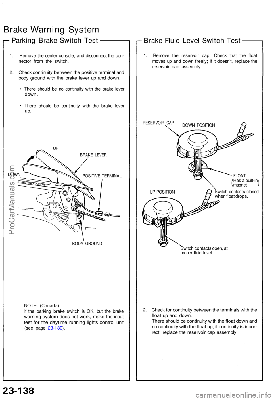
1. Remov e th e cente r console , an d disconnec t th e con -
necto r fro m th e switch .
2. Chec k continuit y betwee n th e positiv e termina l an d
bod y groun d wit h th e brak e leve r u p an d down .
• Ther e shoul d b e n o continuit y wit h th e brak e leve r
down .
• Ther e shoul d b e continuit y wit h th e brak e leve r
up.
DOW N
BRAK E LEVE R
POSITIV E TERMINA L
BODY GROUN D
NOTE: (Canada )
I f th e parkin g brak e switc h i s OK , bu t th e brak e
warnin g syste m doe s no t work , mak e th e inpu t
test fo r th e daytim e runnin g light s contro l uni t
(see pag e 23-180 ).
Brak e Flui d Leve l Switc h Tes t
1. Remov e th e reservoi r cap . Chec k tha t th e floa t
move s u p an d dow n freely ; i f i t doesn't , replac e th e
reservoi r ca p assembly .
RESERVOI R CA P
FLOAT
Has a built-i nmagne t
Switch contact s close dwhen floa t drops .
Switc h contact s open , a t
prope r flui d level .
2. Chec k fo r continuit y betwee n th e terminal s wit h th e
floa t u p an d down .
There shoul d b e continuit y wit h th e floa t dow n an d
no continuit y wit h th e floa t up ; i f continuit y is incor -
rect, replac e th e reservoi r ca p assembly .
UP POSITIO N
DOWN POSITIO N
UP
ProCarManuals.com
Page 802 of 1640
Interlock System
Control Unit Input Test
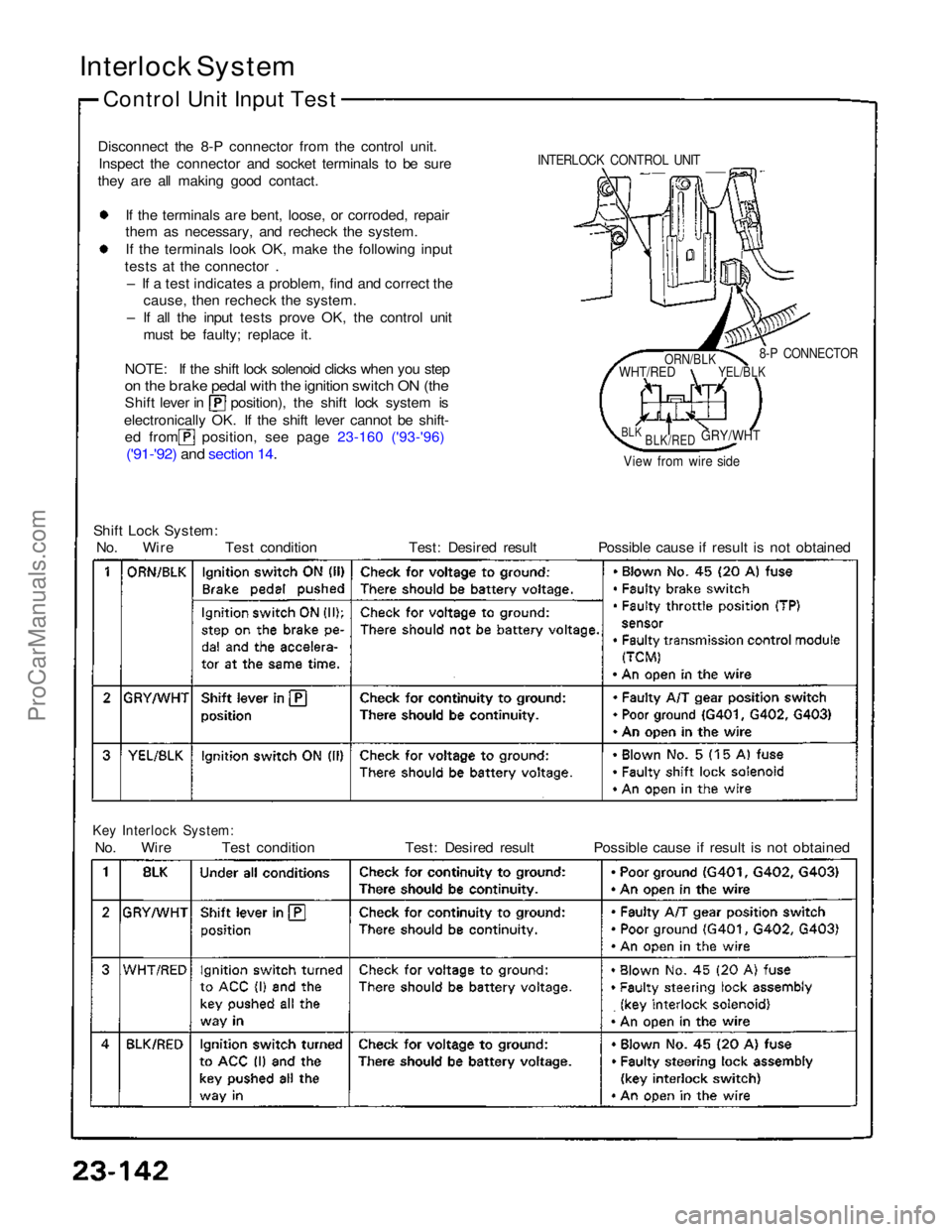
Disconnect the 8-P connector from the control unit. Inspect the connector and socket terminals to be sure
they are all making good contact.
If the terminals are bent, loose, or corroded, repair
them as necessary, and recheck the system.
I
f
the terminals look OK, make the following input
tests at the connector .
– If a test indicates a problem, find and correct the cause, then recheck the system.
– If all the input tests prove OK, the control unit must be faulty; replace it.
NOTE: If the shift lock solenoid clicks when you step
on the brake pedal with the ignition switch ON (the
Shift lever in position), the shift lock system is
electronically OK. If the shift lever cannot be shift-
ed from position, see page 23-160 ('93-'96)
('91-'92) and section 14
.
Shift Lock System:
No. Wire Test condition Test: Desired result Possible cause if result is not obtained
Key Interlock System:
No. Wire Test condition Test: Desired result Possible cause if result is not obtained
8-P CONNECTOR
View from wire side
INTERLOCK CONTROL UNIT
ORN/BLK
WHT/RED
YEL/BLK
BLK
BLK/RED
GRY/WHTProCarManuals.com
Page 805 of 1640
Safety Indicator
Component Location index
SRS components are located in this area. Review the SRS
component locations, precautions, and procedures in the
SRS section (24) before performing repairs or service.
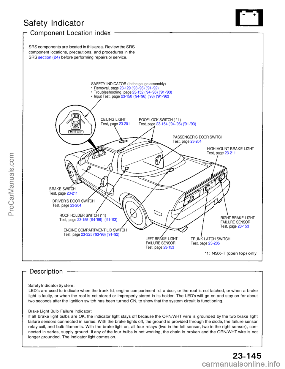
SAFET
Y
INDICATOR (In the gauge assembly)
Removal, page 23-129 ('93-'96) ('91-'92)
Troubleshooting, page 23-152 ('94-'96) ('91-'93)
Input Test, page 23-150 ('94-'96) ('93) ('91-'92)
CEILING LIGHT
Test, page 23-201
ROOF LOCK SWITCH ( * 1)
Test, page 23-154 ('94-'96) ('91-'93)
PASSENGER'S DOOR SWITCH
Test, page 23-204
HIGH MOUNT BRAKE LIGHT
Test, page 23-211
BRAKE SWITCH
Test, page 23-211
DRIVER'S DOOR SWITCH
Test, page 23-204
ROOF HOLDER SWITCH (* 1)
Test, page 23-155 ('94-'96) ('91-'93)
ENGINE COMPARTMENT LID SWITCH
Test, page 23-325 ('93-'96) ('91-'92)
LEFT BRAKE LIGHT
FAILURE SENSOR
Test, page 23-153
TRUNK LATCH SWITCH
Test, page 23-205
RIGHT BRAKE LIGHT
FAILURE SENSOR
Test, page 23-153
*1: NSX-T (open top) only
Description
Safety Indicator System: LED's are used to indicate when the trunk lid, engine compartment lid, a door, or the roof is not latched, or when a brake
light is faulty, or when the roof is not stored or improperly stored in its holder. The LED's will go on and stay on for about
two seconds after the ignition switch has been turned ON, to show that the system circuit is functioning.
Brake Light Bulb Failure Indicator:
If all brake light bulbs are OK, the indicator light stays off because the ORN/WHT wire is grounded by the two brake light
failure sensors connected in series. With the brake lights off, the ground is provided through the diode, the failure sensor relay coil, and bulb filaments. With the brake light on, all four relays (two in the left sensor, two in the right sensor), con-
nected in series, supply ground. If any of the four bulbs is not working, the chain is broken and the ORN/WHT wire is not
longer grounded. The indicator light comes on.ProCarManuals.com
Page 809 of 1640
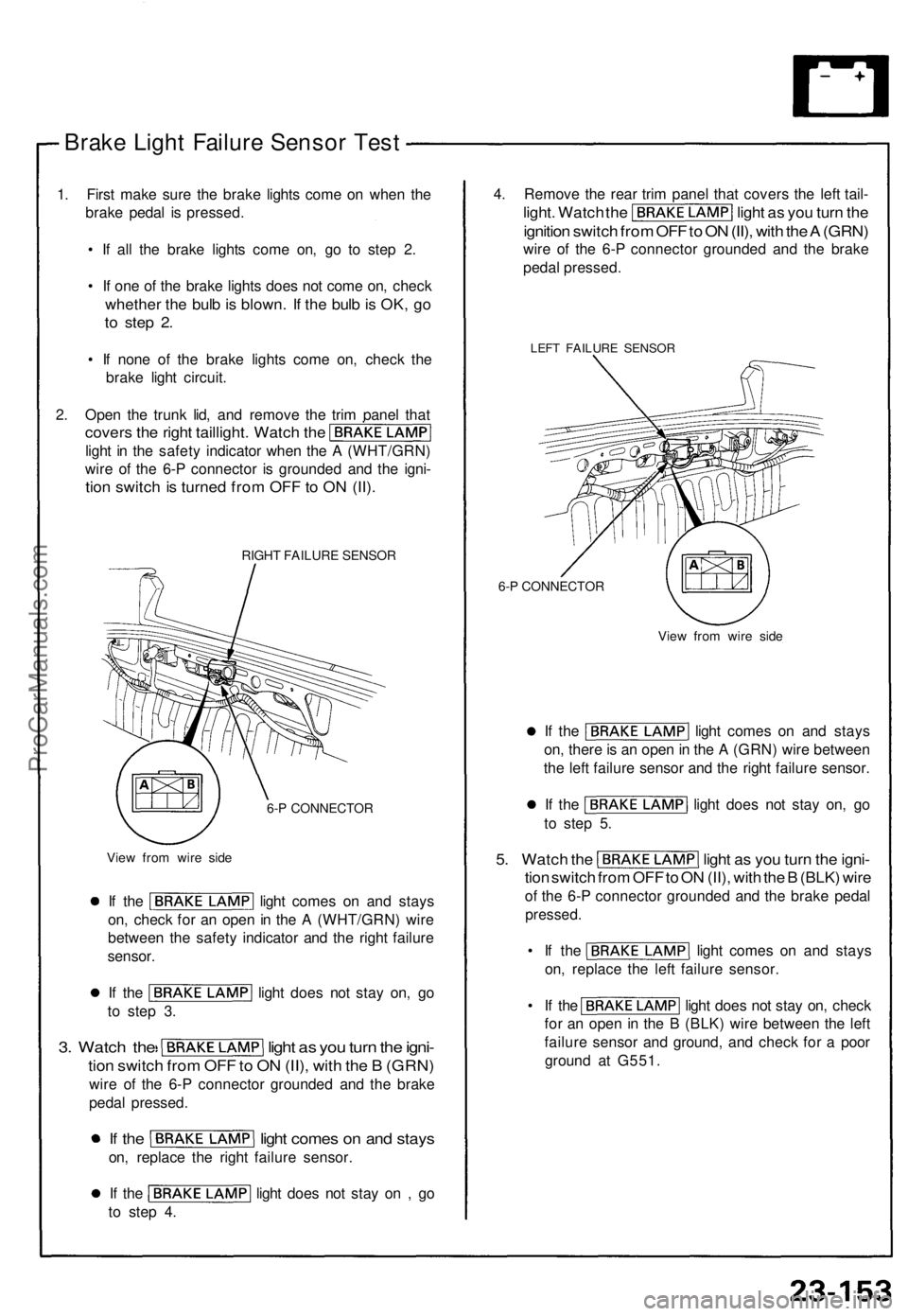
Brake Ligh t Failur e Senso r Tes t
1. Firs t mak e sur e th e brak e light s com e o n whe n th e
brak e peda l i s pressed .
• I f al l th e brak e light s com e on , g o t o ste p 2 .
• I f on e o f th e brak e light s doe s no t com e on , chec k
whethe r th e bul b is blown . I f th e bul b is OK , g o
to ste p 2 .
• I f non e of the brak e light s com e on , chec k th e
brak e ligh t circui t.
2 . Ope n th e trun k lid , an d remov e th e tri m pane l tha t
cover s th e righ t taillight . Watc h th e
ligh t i n th e safet y indicato r whe n th e A (WHT/GRN )
wir e o f th e 6- P connecto r i s grounde d an d th e igni -
tion switc h is turne d fro m OF F to O N (II) .
RIGH T FAILUR E SENSO R
6- P CONNECTO R
Vie w fro m wir e sid e
If th e ligh t come s o n an d stay s
on , chec k fo r a n ope n in th e A (WHT/GRN ) wir e
betwee n th e safet y indicato r an d th e righ t failur e
sensor .
If th e ligh t doe s no t sta y on , g o
t o ste p 3 .
3. Watc h th e ligh t a s yo u tur n th e igni -
tion switc h fro m OF F to O N (II) , wit h th e B (GRN )
wire o f th e 6- P connecto r grounde d an d th e brak e
peda l pressed .
If th e ligh t come s o n an d stay s
on, replac e th e righ t failur e sensor .
If th e ligh t doe s no t sta y o n , g o
t o ste p 4 . 4
. Remov e th e rea r tri m pane l tha t cover s th e lef t tail -
light . Watc h th e ligh t a s yo u tur n th e
ignitio n switc h fro m OF F to O N (II) , wit h th e A (GRN )
wire o f th e 6- P connecto r grounde d an d th e brak e
peda l pressed .
LEFT FAILUR E SENSO R
6-P CONNECTO R
View fro m wir e sid e
If th e ligh t come s o n an d stay s
on , ther e is a n ope n in th e A (GRN ) wir e betwee n
th e lef t failur e senso r an d th e righ t failur e sensor .
If th e ligh t doe s no t sta y on , g o
t o ste p 5 .
5. Watc h th e ligh t a s yo u tur n th e igni -
tion switc h fro m OF F to O N (II) , wit h th e B (BLK ) wir e
of th e 6- P connecto r grounde d an d th e brak e peda l
pressed .
• I f th e ligh t come s o n an d stay s
on , replac e th e lef t failur e sensor .
• I f th e ligh t doe s no t sta y on , chec k
fo r a n ope n in th e B (BLK ) wir e betwee n th e lef t
failur e senso r an d ground , an d chec k fo r a poo r
groun d a t G551 .
ProCarManuals.com
Page 848 of 1640
Taillights
Replacement
1. Open the trunk lid, and remove the rear trim panel.
2. Disconnect the 8-P connector and 2-P connector
from the taillight assembly.
3. Disconnect the 2-P connector from the trunk key
cylinder switch.
8-P CONNECTOR
2-P CONNECTOR
TRUNK KEY CYLINDER
CONNECTOR
REAR TRIM PANEL
4. Remove the four mounting nuts and rear panel, then
remove the ten mounting nuts and the taillight as-
sembly.
NEW GASKET
REAR PANEL
TAILLIGHT ASSEMBLY
5. Inspect the gasket; if it is distorted or stays com-
pressed, replace it.
6. After installing, run water over the lights to make
sure they don't leak.
Bulb Replacement
1. Open the trunk lid, and remove the rear trim panel.
2. Turn each socket 45° counterclockwise to remove
them from the taillight housing.
SOCKET
TURN SIGNAL LIGHT BULB (45CP)
and BRAKE LIGHT/TAILLIGHT BULBS (32CP/2CP)
TAILLIGHT BULB (2CP)
BACK-UP LIGHT BULB (32CP)
3. Remove the bulbs from the sockets.ProCarManuals.com
Page 859 of 1640
Brake Lights
Component Location Index
BRAKE SWITCH
Test, page 23-211
HIGH MOUNT BRAKE LIGHT (LED)
LED Replacement, page 23-212
('94-'96) ('91-'93)
Replacement, page 23-212 ('94-'96) ('91-'93) Test, page 23-211
RIGHT TAILLIGHT
Bul
b
Replacement, page 23-196
Failure Sensor Test, page 23-153
LEFT TAILLIGHT Bulb Replacement, page 23-196 Failure Sensor Test, page 23-153
ProCarManuals.com