1991 ACURA NSX brake
[x] Cancel search: brakePage 973 of 1640
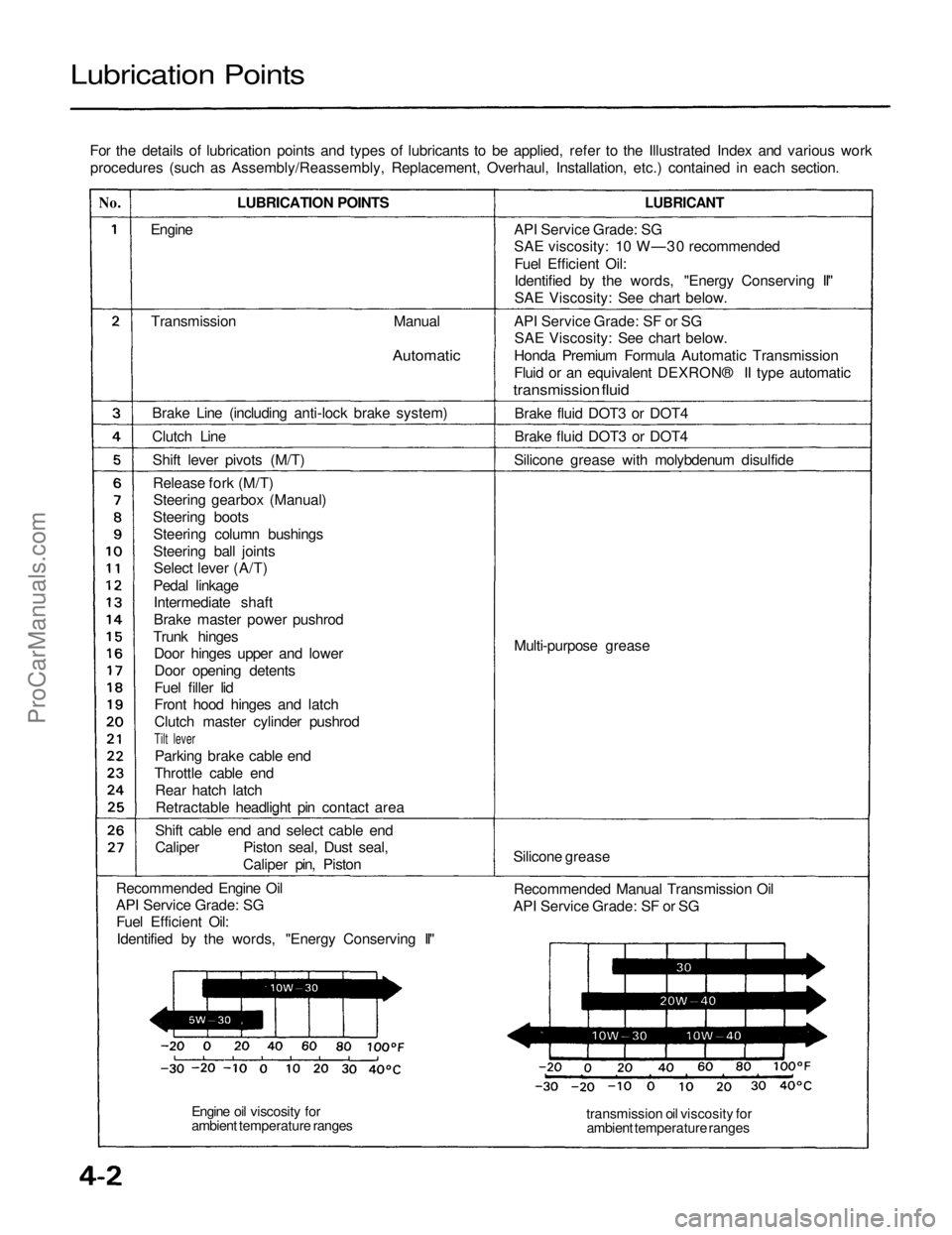
Lubrication Points
For the details of lubrication points and types of lubricants to be applied, refer to the Illustrated Index and various workprocedures (such as Assembly/Reassembly, Replacement, Overhaul, Installation, etc.) contained in each section.
No.
LUBRICATION POINTS
LUBRICANT
Engine
Transmission
Manual
Automatic
Brake Line (including anti-lock brake system)
Clutch Line Shift lever pivots (M/T)Release fork (M/T)Steering gearbox (Manual)
Steering boots Steering column bushings
Steering ball jointsSelect lever (A/T)
Pedal linkage Intermediate shaft
Brake master power pushrod
Trunk hinges Door hinges upper and lower
Door opening detents
Fuel filler lid
Front hood hinges and latch
Clutch master cylinder pushrod
Tilt lever
Parking brake cable end
Throttle cable end Rear hatch latchRetractable headlight pin contact area
Shift cable end and select cable end
Caliper Piston seal, Dust seal, Caliper pin, Piston
Recommended Engine Oil
API Service Grade: SG Fuel Efficient Oil:
Identified by the words, "Energy Conserving II" API Service Grade: SG
SAE viscosity: 10 W—30 recommended
Fuel Efficient Oil:
Identified by the words, "Energy Conserving II"
SAE Viscosity: See chart below.
API Service Grade: SF or SG SAE Viscosity: See chart below.
Honda Premium Formula Automatic Transmission
Fluid or an equivalent DEXRON® II type automatic
transmission fluid
Brake fluid DOT3 or DOT4
Brake fluid DOT3 or DOT4
Silicone grease with molybdenum disulfide
Multi-purpose grease
Silicone grease Recommended Manual Transmission Oil
API Service Grade: SF or SG
transmission oil viscosity forambient temperature ranges
Engine oil viscosity for
ambient temperature rangesProCarManuals.com
Page 976 of 1640
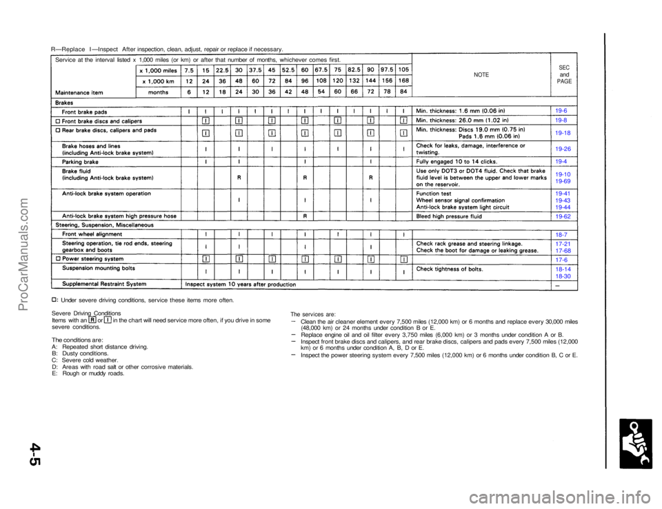
R—Replace I —Inspect After inspection, clean, adjust, repair or replace if necessary.
NOTE
SEC
and
PAGE
Service at the interval listed x 1,000 miles (or km) or after that number of months, whichever comes first.
19-6
19-8
19-18
Under severe driving conditions, service these items more often.
Severe Driving Conditions Items with an or in the chart will need service more often, if you drive in some
severe conditions.
The conditions are:
A: Repeated short distance driving.
B: Dusty conditions.
C: Severe cold weather. D: Areas with road salt or other corrosive materials.
E: Rough or muddy roads. 18-14
18-30
17-6
17-21
17-68
18-7
19-62
19-41
19-43
19-44 19-10
19-69 19-4
19-26
The services are:
Clean the air cleaner element every 7,500 miles (12,000 km) or 6 months and replace every 30,000 miles(48,000 km) or 24 months under condition B or E.
Replace engine oil and oil filter every 3,750 miles (6,000 km) or 3 months under condition A or B.
Inspect front brake discs and calipers, and rear brake discs, calipers and pads every 7,500 miles (12,000
km) or 6 months under condition A, B, D or E.
Inspect the power steering system every 7,500 miles (12,000 km) or 6 months under condition B, C or E.ProCarManuals.com
Page 989 of 1640
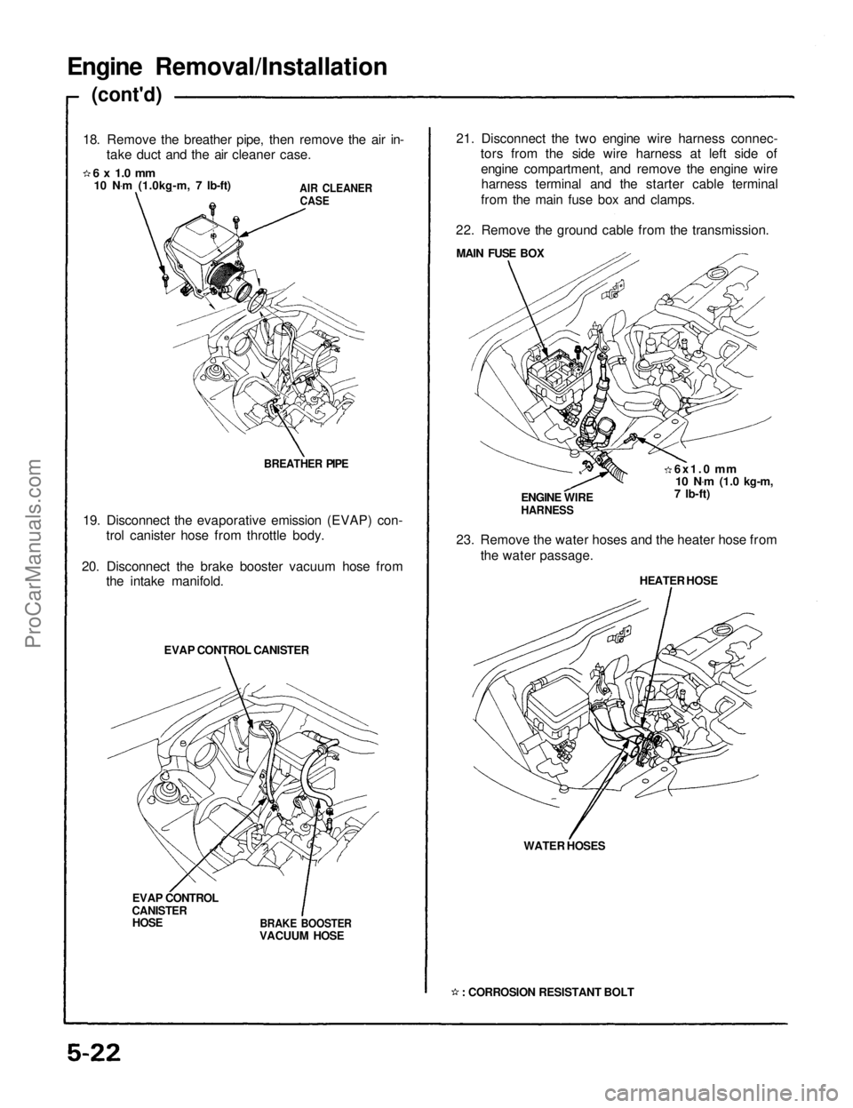
Engine Removal/Installation
(cont'd)
18. Remove the breather pipe, then remove the air in- take duct and the air cleaner case.
6 x 1.0 mm
10 N .
m (1.0kg-m, 7 Ib-ft)
AIR CLEANER
CASE
BREATHER PIPE
19. Disconnect the evaporative emission (EVAP) con- trol canister hose from throttle body.
20. Disconnect the brake booster vacuum hose from the intake manifold.
EVAP CONTROL CANISTER
EVAP CONTROL
CANISTER
HOSE
BRAKE BOOSTER
VACUUM HOSE 21. Disconnect the two engine wire harness connec-
tors from the side wire harness at left side of
engine compartment, and remove the engine wireharness terminal and the starter cable terminal
from the main fuse box and clamps.
22. Remove the ground cable from the transmission. MAIN FUSE BOX
6x1.0
mm
10 N .
m
(1.0 kg-m,
7 Ib-ft)
ENGINE WIRE
HARNESS
23. Remove the water hoses and the heater hose from the water passage.
HEATER HOSE
WATER HOSES
: CORROSION RESISTANT BOLTProCarManuals.com
Page 991 of 1640
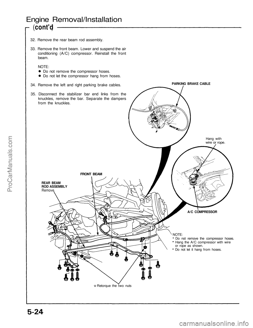
Engine Removal/Installation
(cont'd )
32. Remove the rear beam rod assembly.
33. Remove the front beam. Lower and suspend the air conditioning (A/C) compressor. Reinstall the frontbeam.
NOTE:
PARKING BRAKE CABLE
Hang with
wire or rope.
FRONT BEAM
REAR BEAM
ROD ASSEMBLY
Remove.
A/C COMPRESSOR
Do not remove the compressor hoses.
Hang the A/C compressor with wire
or rope as shown.
Do not let it hang from hoses.
Retorque the two nuts
NOTE:
Do not remove the compressor hoses.
Do not let the compressor hang from hoses.
34. Remove the left and right parking brake cables.
35. Disconnect the stabilizer bar end links from the knuckles, remove the bar. Separate the dampers
from the knuckles.ProCarManuals.com
Page 992 of 1640
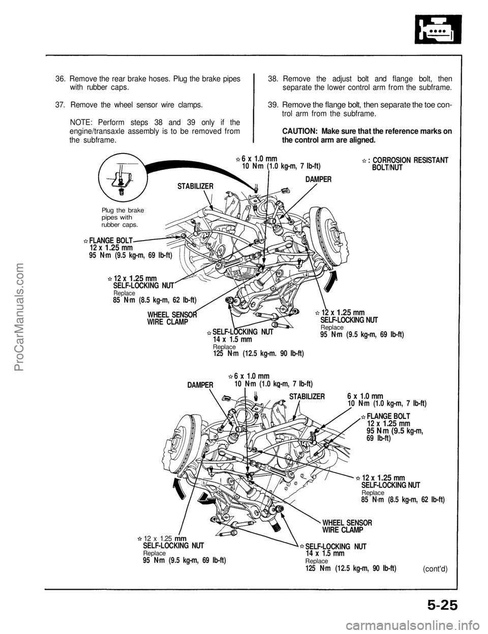
36. Remove the rear brake hoses. Plug the brake pipes
with rubber caps.
37. Remove the wheel sensor wire clamps. NOTE: Perform steps 38 and 39 only if the
engine/transaxle assembly is to be removed from
the subframe. 38. Remove the adjust bolt and flange bolt, then
separate the lower control arm from the subframe.
39. Remove the flange bolt, then separate the toe con-
trol arm from the subframe.
CAUTION: Make sure that the reference marks on
the control arm are aligned.
: CORROSION RESISTANTBOLT/NUT
6 x 1.0 mm
10 N .
m (1.0 kg-m, 7 Ib-ft)
DAMPER
STABILIZER
Plug the brake
pipes with
rubber caps.
FLANGE BOLT
12 x
1.25
mm
95 N .
m (9.5 kg-m, 69 Ib-ft)
12 x
1.25
mm
SELF-LOCKING NUT
Replace
85 N .
m (8.5 kg-m, 62 Ib-ft)
WHEEL SENSOR
WIRE CLAMP
SELF-LOCKING NUT
14 x 1.5 mm
Replace
125 N .
m (12.5 kg-m. 90 Ib-ft)
12 x
1.25
mm
SELF-LOCKING NUT
Replace
95 N .
m (9.5 kg-m, 69 Ib-ft)
DAMPER
6 x 1.0 mm
10 N .
m (1.0 kq-m, 7 Ib-ft)
STABILIZER
6 x 1.0 mm
10 N .
m (1.0 kg-m, 7 Ib-ft)
FLANGE BOLT
12 x
1.25
mm
95 N·m
(9.5
kg-m,
69 Ib-ft)
12 x
1.25
mm
SELF-LOCKING NUT
Replace
85 N·m (8.5 kg-m, 62 Ib-ft)
WHEEL SENSOR
WIRE CLAMP
SELF-LOCKING NUT
14 x 1.5 mm
Replace
125 N .
m (12.5 kg-m, 90 Ib-ft)
(cont'd)
12 x
1.25
mm
SELF-LOCKING NUT
Replace
95 N .
m (9.5 kg-m, 69 Ib-ft)ProCarManuals.com
Page 998 of 1640
Engine Removal/Installation
(cont'd)
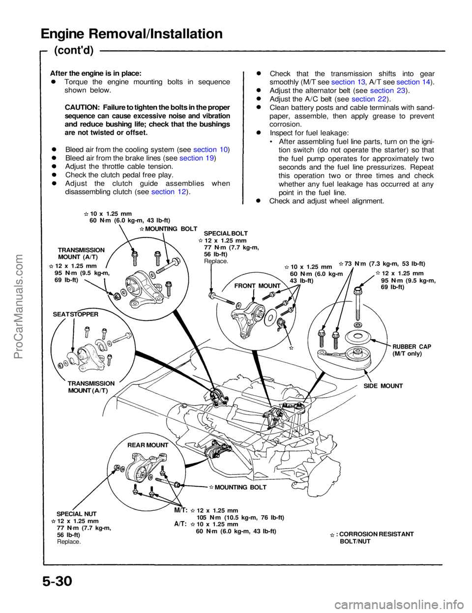
Torque the engine mounting bolts in sequenceshown below.
CAUTION: Failure to tighten the bolts in the proper
sequence can cause excessive noise and vibration
and reduce bushing life; check that the bushings
are not twisted or offset.
Bleed air from the cooling system (see section 10)
Bleed air from the brake lines (see section 19)
Adjust the throttle cable tension.
Check the clutch pedal free play.
Adjust the clutch guide assemblies when
disassembling clutch (see section 12). Check that the transmission shifts into gear
smoothly (M/T see section 13, A/T see section 14).
Adjust the alternator belt (see section 23).
Adjust the A/C belt (see section 22).
Clean battery posts and cable terminals with sand-
paper, assemble, then apply grease to prevent
corrosion.
Inspect for fuel leakage:
• After assembling fuel line parts, turn on the igni- tion switch (do not operate the starter) so that
the fuel pump operates for approximately two seconds and the fuel line pressurizes. Repeat
this operation two or three times and check whether any fuel leakage has occurred at any
point in the fuel line.
Check and adjust wheel alignment.
10 x
1.25
mm
60 N .
m (6.0 kg-m, 43 Ib-ft)
MOUNTING BOLT SPECIAL BOLT
12 x
1.25
mm
77 N .
m
(7.7 kg-m,
56 Ib-ft)
Replace.
10 x
1.25
mm
60 N .
m
(6.0 kg-m
43 Ib-ft) 73 N.m (7.3 kg-m, 53 Ib-ft)
12 x
1.25
mm
95 N .
m
(9.5 kg-m,
69 Ib-ft)
RUBBER CAP
(M/T only)
SIDE MOUNT
: CORROSION RESISTANT
BOLT/NUT
12 x
1.25
mm
105 N .
m (10.5 kg-m, 76 Ib-ft)
10 x
1.25
mm
60 N .
m (6.0 kg-m, 43 Ib-ft) MOUNTING BOLT FRONT MOUNT
TRANSMISSION
MOUNT (A/T)
12 x
1.25
mm
95 N .
m
(9.5 kg-m,
69 Ib-ft)
SEAT STOPPER
TRANSMISSION
MOUNT (A/T)
REAR MOUNT
SPECIAL NUT
12 x
1.25
mm
77 N .
m
(7.7 kg-m,
56 Ib-ft)
Replace.
M/T:
A/T:
After the engine is in place:ProCarManuals.com
Page 1015 of 1640
14. Relieve fuel pressure (see section 11).
Do not smoke while working on fuel
system; keep open flame or spark away from work
area. Drain fuel only into an approved container.
1 5. Disconnect the fuel feed pipe and the return hose
(page 5-21).
16. Remove the ignition coil covers, the wire harness covers, the ignition coils and the connectors (page
6-23).
17. Remove the water hoses, then remove the expan- sion tank (page 5-21).
18. Remove the breather hose, and the air cleaner housing (page 5-22).
19. Remove the brake booster hose, the evaporative emission (EVAP) control canister hose and other
hoses from the intake manifold and throttle body
(page 5-22).
20. Remove the emission control box (page 5-23). Do not disconnect emission hose.Disconnect the three connectors before
removing.
21. Remove the connector, the terminal and the alternator.
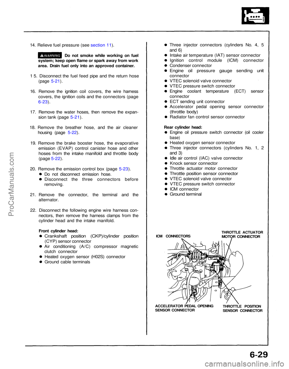
22. Disconnect the following engine wire harness con- nectors, then remove the harness clamps from thecylinder head and the intake manifold.
Front cylinder head:
Crankshaft position (CKP)/cylinder position
(CYP) sensor connector
Air conditioning (A/C) compressor magnetic clutch connector
Heated oxygen sensor (H02S) connector
Ground cable terminals Three injector connectors (cylinders No. 4, 5
and 6)
Intake air temperature (IAT) sensor connector
Ignition control module (ICM) connector
Condenser connector
Engine oil pressure gauge sending unit
connector
VTEC solenoid valve connector
VTEC pressure switch connector
Engine coolant temperature (ECT) sensor
connector
ECT sending unit connector
Accelerator pedal opening sensor connector
(throttle body)
Radiator fan control sensor connector
Rear cylinder head: Engine oil pressure switch connector (oil cooler
base)
Heated oxygen sensor connector
Three injector connectors (cylinders No. 1, 2
and 3)
Idle air control (IAC) valve connector
Knock sensor connector
Throttle actuator motor connector
Throttle position sensor connector
VTEC solenoid valve connectorVTEC pressure switch connector
ICM connector
Ground terminal
ICM CONNECTORS THROTTLE ACTUATOR
MOTOR CONNECTOR
THROTTLE POSITION
SENSOR CONNECTOR
ACCELERATOR PEDAL OPENING
SENSOR CONNECTORProCarManuals.com
Page 1106 of 1640
Idle Control System
Idle Speed Setting
Inspection/Adjustment NOTE: (Canada) Pull the parking brake lever up.
Start the engine, then check that the head lights
are
off.
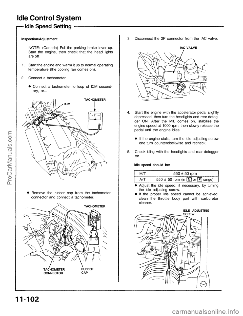
1. Start the engine and warm it up to normal operating temperature (the cooling fan comes on).
2. Connect a tachometer. Connect a tachometer to loop of ICM second-
ary, or...
TACHOMETER
ICM
Remove the rubber cap from the tachometer
connector and connect a tachometer.
TACHOMETER
TACHOMETER CONNECTOR
RUBBER
CAP
3. Disconnect the 2P connector from the IAC valve.
IAC VALVE
4. Start the engine with the accelerator pedal slightly depressed, then turn the headlights and rear defog-
ger ON. After the MIL comes on, stabilize the
engine speed at 1000 rpm, then slowly release the
pedal until the engine idles.
If the engine stalls, turn the idle adjusting screw
one turn counterclockwise and recheck.
5. Check idling with the headlights and rear defogger
on.
Idle speed should be:
M/T
A/T
550 ± 50 rpm
550 ± 50 rpm (in or range)
Adjust the idle speed, if necessary, by turning
the idle adjusting screw.
If the proper idle speed cannot be achieved,
clean the throttle body port with carburetor
cleaner.
IDLE ADJUSTING
SCREWProCarManuals.com