Page 1575 of 1640

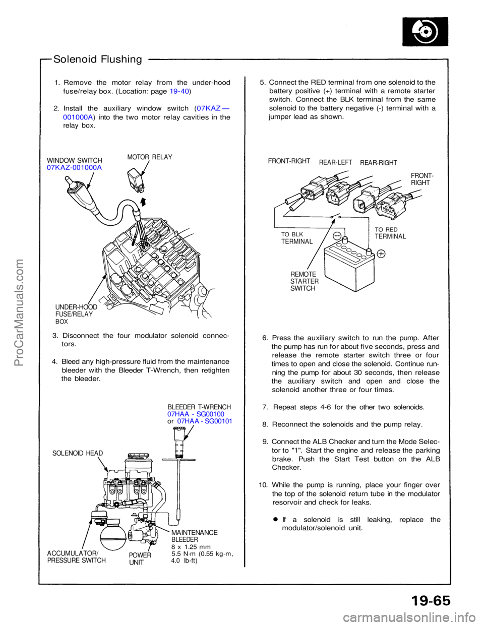
Solenoid Flushing
1. Remove the motor relay from the under-hood fuse/relay box. (Location: page 19 - 40)
2. Install the auxiliary window switch (07KAZ — 001000A) into the two motor relay cavities in the
relay box.
MOTOR RELAY
WINDOW SWITCH
07KAZ-001000A
UNDER-HOOD
FUSE/RELAY
BOX
3. Disconnect the four modulator solenoid connec- tors.
4. Bleed any high-pressure fluid from the maintenance bleeder with the Bleeder T-Wrench, then retighten
the bleeder.
BLEEDER T-WRENCH
07HAA - SG00100
or 07HAA - SG00101
SOLENOID HEAD
MAINTENANCE
BLEEDER
8 x
1.25
mm
5.5 N·m
(0.55 kg-m,
4.0 Ib-ft)
POWER
UNIT
ACCUMULATOR/
PRESSURE SWITCH
6. Press the auxiliary switch to run the pump. After
the pump has run for about five seconds, press andrelease the remote starter switch three or four
times to open and close the solenoid. Continue run- ning the pump for about 30 seconds, then release
the auxiliary switch and open and close the solenoid another three or four times.
7. Repeat steps 4-6 for the other two solenoids.
8. Reconnect the solenoids and the pump relay. 9. Connect the ALB Checker and turn the Mode Selec- tor to "1". Start the engine and release the parkingbrake. Push the Start Test button on the ALB
Checker.
10. While the pump is running, place your finger over the top of the solenoid return tube in the modulatorresorvoir and check for leaks. If a solenoid is still leaking, replace the
modulator/solenoid
unit.
REMOTE
STARTER
SWITCH
TO BLK
TERMINAL
TO RED
TERMINAL
FRONT-
RIGHT
FRONT-RIGHT
REAR-LEFT
REAR-RIGHT
5. Connect the RED terminal from one solenoid to the
battery positive (+) terminal with a remote starter
switch. Connect the BLK terminal from the same
solenoid to the battery negative (-) terminal with a
jumper lead as shown.ProCarManuals.com
Page 1576 of 1640

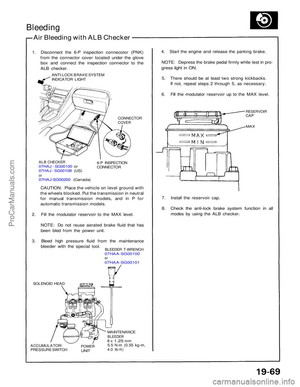
Bleeding
Air Bleeding with ALB Checker
1. Disconnect the 6-P inspection connecotor (PNK) from the connector cover located under the glovebox and connect the inspection connector to the
ALB checker.
ANTI-LOCK BRAKE SYSTEM
INDICATOR LIGHT
CONNECTOR
COVER
ALB CHECKER
07HAJ - SG00100 or
07HAJ - SG0010B (US)
or
07HAJ-SG00200 (Canada)
6-P INSPECTION
CONNECTOR
CAUTION: Place the vehicle on level ground with
the wheels blocked. Put the transmission in neutral
for manual transmission models, and in P for automatic transmission models.
2. Fill the modulator reservoir to the MAX level.
NOTE: Do not reuse aerated brake fluid that has
been bled from the power unit.
3. Bleed high pressure fluid from the maintenance bleeder with the special tool.
BLEEDER T-WRENCH
07HAA-SG00100
or
07HAA-SG00101
SOLENOID HEAD
ACCUMULATOR/
PRESSURE SWITCH
POWER
UNIT
MAINTENANCE
BLEEDER
8 x
1.25
mm
5.5 N·m
(0.55 kg-m,
4.0 Ib-ft) 7. Install the reservoir cap.
8. Check the anti-lock brake system function in all
modes by using the ALB checker.
MAX
RESERVOIR
CAP
4. Start the engine and release the parking brake.
NOTE: Depress the brake pedal firmly while test in pro-
gress light in ON.
5. There should be at least two strong kickbacks. If not, repeat steps 2 through 5, as necessary.
6. Fill the modulator reservoir up to the MAX level.ProCarManuals.com
Page 1580 of 1640

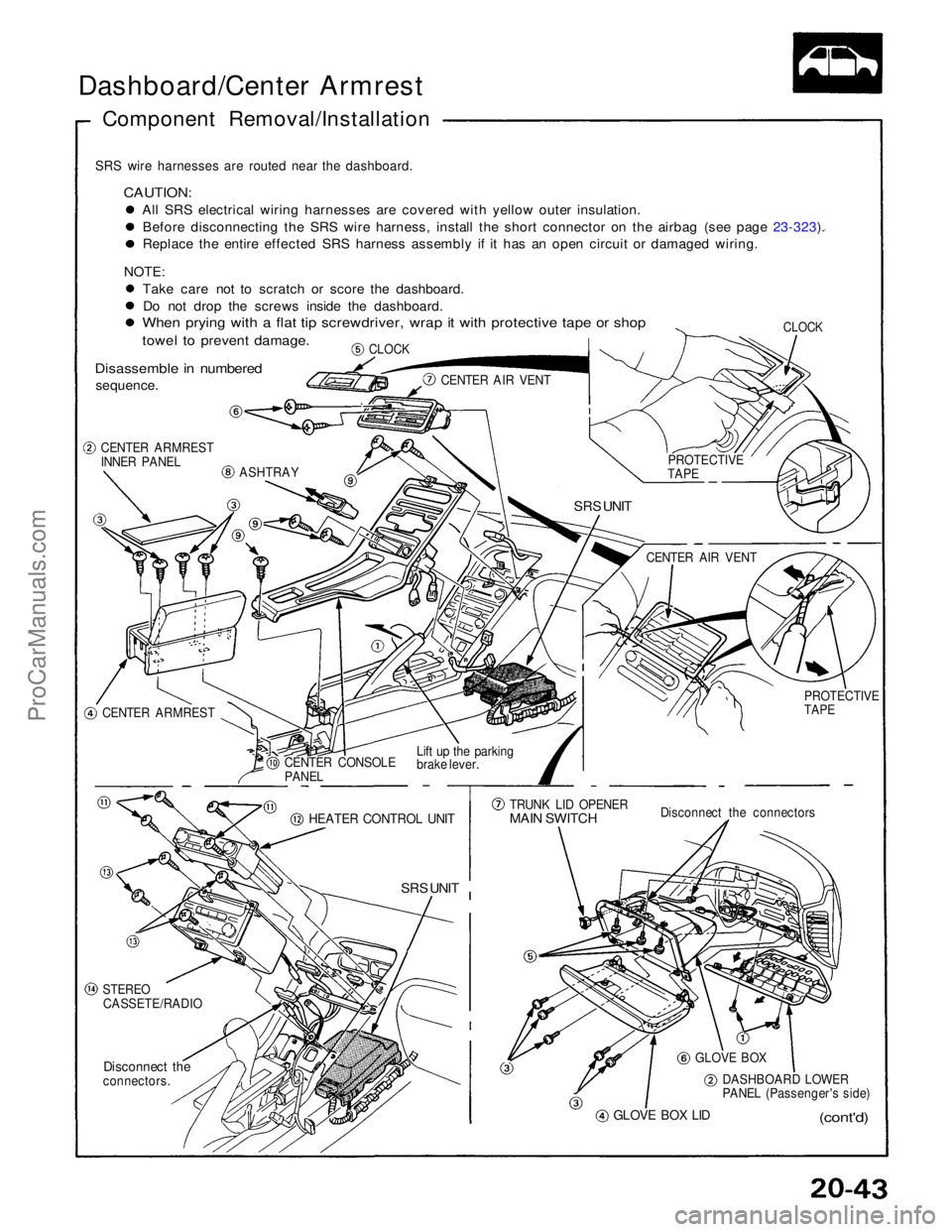
Dashboard/Center Armrest
Component Removal/Installation
SRS wire harnesses are routed near the dashboard.
CAUTION:
All SRS electrical wiring harnesses are covered with yellow outer insulation.Before disconnecting the SRS wire harness, install the short connector on the airbag (see page 23-323). Replace the entire effected SRS harness assembly if it has an open circuit or damaged wiring.
NOTE: Take care not to scratch or score the dashboard.Do not drop the screws inside the dashboard.
When prying with a flat tip screwdriver, wrap it with protective tape or shop
towel to prevent damage.
Disassemble in numbered
sequence.
CLOCK
CLOCK
CENTER AIR VENT
CENTER ARMREST
INNER PANEL
ASHTRAY
SRS UNIT
CENTER ARMREST CENTER CONSOLE
PANEL
Lift up the parking
brake lever.
HEATER CONTROL UNIT
SRS UNIT
STEREO
CASSETE/RADIO
Disconnect the
connectors.
GLOVE BOX LID
(cont'd)
DASHBOARD LOWER
PANEL (Passenger's side)
GLOVE BOX
Disconnect the connectors
TRUNK LID OPENER
MAIN SWITCH
PROTECTIVE
TAPE
CENTER AIR VENT
PROTECTIVE
TAPEProCarManuals.com
Page 1585 of 1640

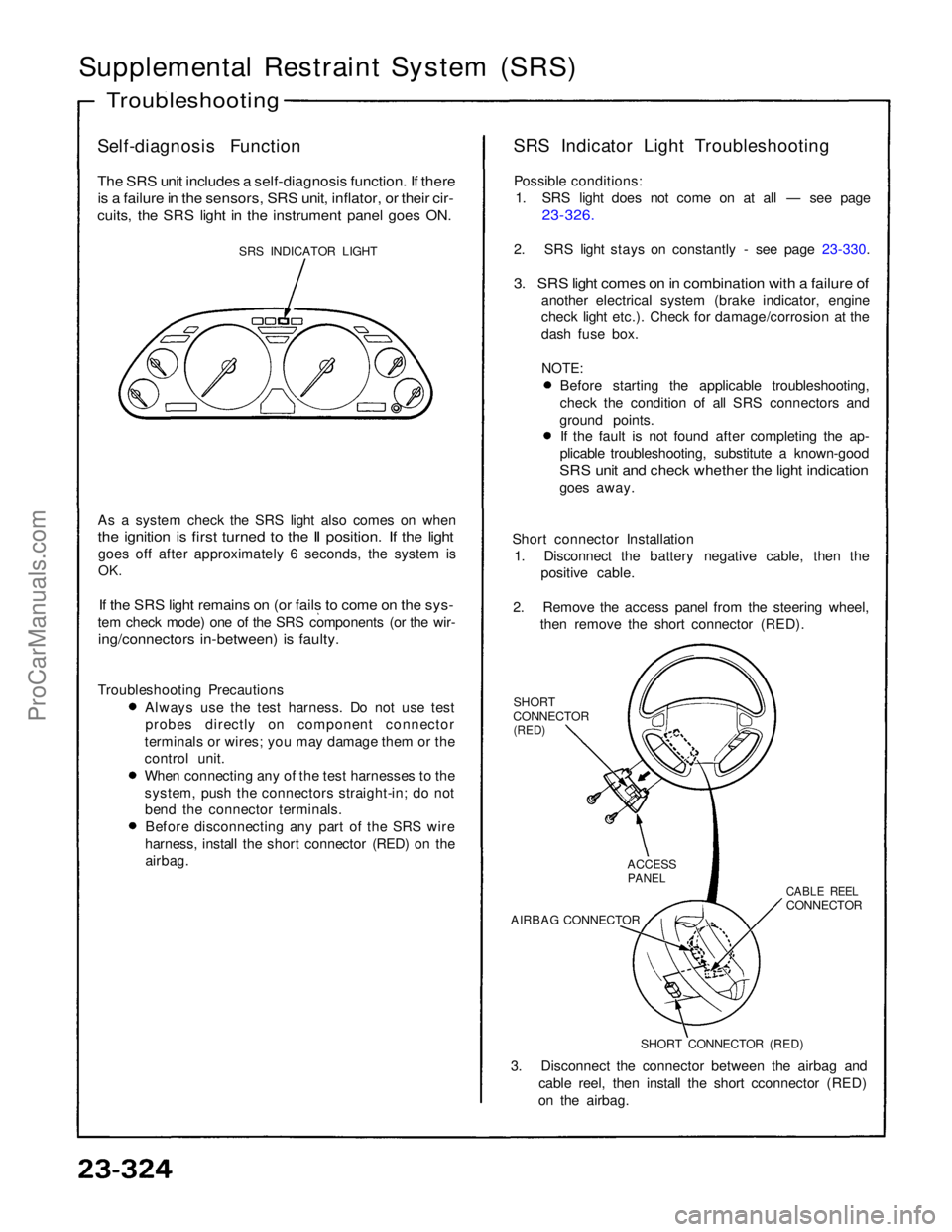
Supplemental Restraint System (SRS)
Self-diagnosis Function
The SRS unit includes a self-diagnosis function. If there
is a failure in the sensors, SRS unit, inflator, or their cir-
cuits, the SRS light in the instrument panel goes ON.
SRS INDICATOR LIGHT
As a system check the SRS light also comes on when
the ignition is first turned to the II position. If the light
goes off after approximately 6 seconds, the system is
OK.
If the SRS light remains on (or fails to come on the sys-
tem check mode) one of the SRS components (or the wir-
ing/connectors in-between) is faulty.
Troubleshooting Precautions Always use the test harness. Do not use test
probes directly on component connector
terminals or wires; you may damage them or the
control unit. When connecting any of the test harnesses to the
system, push the connectors straight-in; do not
bend the connector terminals. Before disconnecting any part of the SRS wire
harness, install the short connector (RED) on the airbag. SRS Indicator Light Troubleshooting
Possible conditions: 1. SRS light does not come on at all — see page
23-326.
2. SRS light stays on constantly - see page 23-330.
3. SRS light comes on in combination with a failure of
another electrical system (brake indicator, engine
check light etc.). Check for damage/corrosion at the
dash fuse box.
NOTE:
Before starting the applicable troubleshooting,
check the condition of all SRS connectors and
ground points. If the fault is not found after completing the ap-
plicable troubleshooting, substitute a known-good
SRS unit and check whether the light indication
goes away.
Short connector Installation 1. Disconnect the battery negative cable, then the positive cable.
2. Remove the access panel from the steering wheel, then remove the short connector (RED).
SHORT
CONNECTOR
(RED)
3. Disconnect the connector between the airbag and cable reel, then install the short cconnector (RED)
on the airbag.
Troubleshooting
SHORT CONNECTOR (RED)
AIRBAG CONNECTOR
CABLE REEL
CONNECTOR
ACCESS
PANELProCarManuals.com
Page 1624 of 1640
Cruise Control
CAUTION:
All SRS electrical wiring harnesses are covered with
yellow outer insulation.
Before disconnecting the SRS wire harness, install
the short connector on the airbag (see page 23-323).
Replace the entire affected SRS harness assembly
if it has an open circuit or damaged wiring.
SRS MAIN WIRE MARNESS
MAIN SWITCH
Test, page 23-295
Replacement, page 23-294
BRAKE LIGHT SWITCH
Test, page 23-308
INDICATOR LIGHT and
DIMMING CIRCUIT
(in the gauge assembly)
Bulb Locations, pages 23-128
CRUISE CONTROL UNIT
Input Test, page 23-292
SET/RESUME SWITCH
Test, page 23-307
Replacement, page 23-307
SHIFT POSITION
CONSOLE SWITCH (A/T)
Test, 23-309
Replacement, page 23-161
CLUTCH SWITCH (M/T)
Test, page 23-308
CABLE REEL
Test, page 23-250
Replacement, page 23-344
Component Location IndexProCarManuals.com
Page 1637 of 1640
Label Locations
SRS CAUTION LABELS: Refer to page 1-14.
BATTERY CAUTION
COOLING FAN
CAUTION
RADIATOR BLEED
PLUG CAUTION
AIR CONDITIONER
CAUTION
EXPANSION
TANK CAP
CAUTION
COOLANT
CAUTION • PRECAUTION
SPARK PLUG
CAUTION
TIRE INFORMATION
EMISSION CONTROL
INFORMATION and
VACUUM HOSE
ROUTING DIAGRAM
FAN CAUTION
RETRACTABLE
HEADLIGHT CAUTION
ALB and BRAKE
FLUID CAUTION ALB CAUTIONProCarManuals.com